1
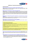
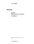
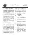
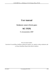
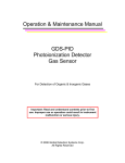
48 Placement and calibration of sensors
Inserting and removing sensors
3.
Remove the black m
manifold casing.
Manifold
Sensor housing
Figure 4-1: Sensor housing and manifold
4. To insert a sensor, gently push the sensor’s pins into the socket pin
of the circuit board so it aligns accordingly. It will fit securely.
5. To remove a sensor, pull the senor up horizontally and remove it
from the sensor chamber.
6. When completed, replace the black manifold over the sensors and
then place the cover over the sensor housing. Tighten the screws
back into place.
Sensor bar- Remove screw 1 & screw 2 and lift off cover.
Screw 1
Air inlet cover
Dial-in
Impactors
Temperature/
Relative Humidity sensor
(Dry bulb thermometer
measures ambient air
temperature)
Screw 2
Toxic sensor
PID sensor
CO2Sensor
Figure 4-2: Sensors’ locations
074-300, RevE
EVM Series