1
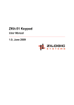
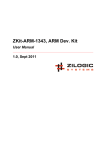
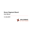
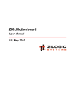
ZKit-51, 8051 Development Kit
User Manual
1.1, June 2011
ZKit-51, 8051 Development Kit User Manual
Rev. 1.1
This work is licensed under the Creative Commons Attribution-Share Alike 2.5 India License. To view a
copy of this license, visit http://creativecommons.org/licenses/by-sa/2.5/in/ or send a letter to Creative
Commons, 171 Second Street, Suite 300, San Francisco, California, 94105, USA.
ZKit-51, 8051 Development Kit User Manual
Rev. 1.1
Table of Contents
1. Introduction ............................................................................................................................ 1
1. Features ........................................................................................................................ 1
2. Board Design ......................................................................................................................... 2
1. Overview ....................................................................................................................... 2
2. Locating Components ..................................................................................................... 2
3. Power Supply ................................................................................................................ 4
4. CPU .............................................................................................................................. 5
5. USB Serial ..................................................................................................................... 6
6. LCD Display .................................................................................................................. 7
7. SPI EEPROM ................................................................................................................ 7
8. I²C RTC ......................................................................................................................... 8
9. Piezoelectric Buzzer ....................................................................................................... 8
10. Debug LEDs ................................................................................................................ 9
11. Keypad ........................................................................................................................ 9
12. Interrupt Key .............................................................................................................. 10
3. Jumpers and Switches ......................................................................................................... 11
1. EXTPWR/USBPWR Jumper ............................................................................................. 11
2. INTR/BUZZ Dip Switch ................................................................................................ 11
3. USBSIO Dip Switch ...................................................................................................... 11
4. External Connectors ............................................................................................................. 12
1. SIO/I²C Header ......................................................................................................... 12
2. PORT-P1/P3 Header ................................................................................................... 12
3. PORT-P0/P4 Header ................................................................................................... 12
4. Phoenix Terminal - EXTIO ............................................................................................ 13
5. Phoenix Terminal - PWR ................................................................................................ 13
Zilogic Systems
Page iii
ZKit-51, 8051 Development Kit User Manual
Rev. 1.1
Chapter 1. Introduction
ZKit-51 is a 8051 micro controller development kit from Zilogic Systems. ZKit-51 is designed for a easy
usage, rapid prototyping and extensive product design.
1. Features
The ZKit-51 offers the following features
• NXP P89V664 micro-controller with 64KB Flash and 1KB RAM
• 18.432MHz crystal
• Power supply, jumper selectable between
– USB
– External 5V supply
• On-board Peripherals
– 16x2 character LCD, with backlight
– USB serial interface, for communication and program download
– 2Kbit SPI EEPROM
– I²C RTC with battery backup
– Piezoelectric buzzer
– Four button keypad
– Push button with hardware de-bounce (interrupt input)
– 2 debug LEDs
• Connectors
– USB, type B connector
– 2.1mm power supply connector
– 20 pin header for P0/P4
– 20 pin header for P1/P3
– 10 pin header for serial communication / I²C
– 2 pin header for powering external devices
– 4 pin header for external I/O
Zilogic Systems
Page 1
ZKit-51, 8051 Development Kit User Manual
Rev. 1.1
Chapter 2. Board Design
1. Overview
A bird's eye view of the devices available on the board, is shown in the following block diagram. Each
device connectivity is described in detail in the following sections.
Figure 2.1. Block Diagram
2. Locating Components
The location of the components on the board are indicated in the following diagrams.
Zilogic Systems
Page 2
ZKit-51, 8051 Development Kit User Manual
Rev. 1.1
Figure 2.2. Front View
Zilogic Systems
Page 3
ZKit-51, 8051 Development Kit User Manual
Rev. 1.1
Figure 2.3. Back View
3. Power Supply
The ZKit-51 can be powered through USB or an external 5V regulated power supply. The power source
can be selected through USBPWR / EXTPWR jumper setting.
Figure 2.4. Power Supply Connection Diagram
Caution
The external power supply, if used, should be a 5V/500mA regulated power
supply, with the polarity shown in the power supply connection diagram.
Zilogic Systems
Page 4
ZKit-51, 8051 Development Kit User Manual
Rev. 1.1
4. CPU
The heart of the ZKit-51 is Philips P89v664 micro-controller. The P89v664 is an 8-bit 80C51 5V low
power micro-controller with 64 kB Flash, 2KB of data RAM and supports In-System Programming (ISP).
The main features of the micro-controller are listed below.
• Dual 100 kHz byte-wide I²C-bus interfaces
• 0 MHz to 40 MHz operating frequency in 12x mode, 20 MHz in 6x mode
• 64 kB of on-chip flash user code memory with ISP and IAP
• 2 kB RAM
• SPI (Serial Peripheral Interface) and enhanced UART
• PCA (Programmable Counter Array) with PWM and Capture/Compare functions
• Three 16-bit timers/counters
• Four 8-bit I/O ports, one 4-bit I/O port
• WatchDog Timer (WDT)
• Support for 12-clock (default) or 6-clock mode selection via ISP
• Low EMI mode (ALE inhibit)
• Power-down mode with external interrupt wake-up
The micro-controller crystal frequency is 18.432 MHz. 8051-based processors generate their serial port
timing using a combination of external crystal and internal programmable divider chains. This crystal
frequency has been selected in order to ensure the following
1. the timing requirements of the controller's serial interface are met.
2. the CPU runs at high speed in 6-clock mode.
Power to the board is sourced either from the +5V external regulated power supply or the via USB power
with the help of jumper selection.
Zilogic Systems
Page 5
ZKit-51, 8051 Development Kit User Manual
Rev. 1.1
Figure 2.5. Micro-controller Block Diagram
5. USB Serial
The ZKit-51 has a FT232R USB to serial UART converter. The FT232R has the following advanced
features:
• The FT232R is fully compliant with the USB 2.0 specification.
• Single chip USB to asynchronous serial data transfer interface.
• Entire USB protocol handled on the chip. No USB specific firmware programming required.
• Supports transmit and receive LED drive signals.
The ZKit-51 uses USB Serial UART for serial communication between PC and the P89V664 MCU. This
is also used to download firmware by activatiing the bootloader of P89V664 MCU. This is called InSystem Programming (ISP).
5.1. In-System Programming
To switch the P89V664 MCU to ISP mode, the following sequence has to be followed.
Zilogic Systems
Page 6
ZKit-51, 8051 Development Kit User Manual
Rev. 1.1
1. Apply hardware reset.
2. Pull PSEN to ground.
3. Release hardware reset.
4. Release PSEN.
The ZKit-51 comes with RESET and PSEN push buttons that can be used to put the MCU into ISP. In
the ZKit-51, the RESET and PSEN pins are also connected to the handshaking signals DTR and RTS of
the USB to serial UART. Flash programming applications like Smash and Flash Magic can utilize this
feature to switch the device into ISP mode automatically, without user intervention.
The following diagram shows the FT232R connection details.
Figure 2.6. FT232R Connection Diagram
6. LCD Display
The ZKit-51 has a HD44780 Hitachi chipset compatible, 16x2 character, LCD. The LCD data lines are
connected to Port 0 and the control lines (RS, R/W, EN) are connected to P2.4, P2.5, P2.6 respectively.
The following diagram shows the LCD pin connection details.
Figure 2.7. LCD Connection Diagram
7. SPI EEPROM
The ZKit-51 has a Microchip 255AA020A EEPROM for data storage. The Microchip 25AA020A is a 2
Kbit Serial EEPROM. The memory is accessed via a simple Serial Peripheral Interface (SPI) compatible
Zilogic Systems
Page 7
ZKit-51, 8051 Development Kit User Manual
Rev. 1.1
serial bus. The bus signals required are a clock input (SCK) plus separate data in (SI) and data out (SO)
lines. Access to the device is controlled through a Chip Select (CS) input.
The SPI EEPROM is connected to the on-chip SPI controller of the P89V664 MCU. The following
diagram shows the EEPROM pin connection details.
Figure 2.8. SPI EEPROM Connection Diagram
8. I²C RTC
The ZKit-51 has an battery backed NXP PCF8563 RTC to keep track of current date and time. The
PCF8563 is a CMOS real-time clock/calendar optimized for low power consumption. A programmable
interrupt output and voltage-low detector are also provided. All addresses and data are transferred
serially via a two-line bidirectional I²C-bus. The maximum bus speed is 400 kbit/s.
The I²C RTC is connected to the primary on-chip I²C controller of the P89V664 MCU. The RTC interrupt is
connected to INT0 through an On/Off dip switch. When the switch is in Off position, INT0 is available for
external usage, through the PORT P1/P3 header. The following diagram shows the RTC pin connection
details.
Figure 2.9. RTC Connection Diagram
9. Piezoelectric Buzzer
The ZKit-51 has a piezoeletric buzzer that can be used to provide audible indications. The buzzer is
connected to P3.4 pin. By rapidly switching the pin, a tone can be generated on the buzzer. Alternatively,
the on-chip PCA (Programmable Counter Array) can be used to generate a pulse train to the buzzer.
Using PWM techniques, both volume and tone can be controlled.
The buzzer is connected to P3.4 pin, through a On/Off dip switch. When the switch is in Off position,
P3.4 is available for external usage, through PORT P1/P3 header. The following diagram shows the
buzzer connection details.
Zilogic Systems
Page 8
ZKit-51, 8051 Development Kit User Manual
Rev. 1.1
Figure 2.10. Buzzer Connection Diagram
10. Debug LEDs
The ZKit-51 has two debug LEDs connected to P1.4 and P1.5, through a non-inverting buffer.
By driving P1.4 and P1.5 low, the LEDs can be switched On. Alternatively, the on-chip PCA
(Programmable Counter Array) can be used to generate a PWM signal to control the LED brightness.
Figure 2.11. LEDs Connection Diagram
11. Keypad
The ZKit-51 has 4 tactile push button switches connected to P2.0 to P2.3. The keypad connection
details are shown in the following diagram.
Figure 2.12. Keypad Connection Diagram
Zilogic Systems
Page 9
ZKit-51, 8051 Development Kit User Manual
Rev. 1.1
12. Interrupt Key
The ZKit-51 has 1 tactile push button switch for testing interrupts. The push button is hardware
debounced and connected to INTR1, through a On/Off dip switch. When the switch is Off, INTR1 is
available for external usage, through PORT P1/P3 header. The following diagram shows the interrupt
key connection details.
Figure 2.13. Interrupt Key Connection Diagram
Zilogic Systems
Page 10
ZKit-51, 8051 Development Kit User Manual
Rev. 1.1
Chapter 3. Jumpers and Switches
1. EXTPWR/USBPWR Jumper
The board can be powered from USB or an external power source. To select the required power source,
the jumper has to set, as specified below.
USB power
To power the board through USB, the jumper should be on the USBPWR
pin and the center pin.
External power
For external 5V power source, the jumper should be on the EXTPWR pin
and the center pin.
Table 3.1. EXTPWR/USBPWR Jumper Pins
Pin
Description
USBPWR
USB Power +5V
Center
To board Vcc
EXTPWR
External Power +5V
2. INTR/BUZZ Dip Switch
The INTR/BUZZ dip switch is used to select the routing between external connector and on board
devices, to the micro-controller. The routing details are given in the following table.
Switch
State
Description
1
ON
CEX3/P3.4 pin is connected to buzzer
OFF
CEX3/P3.4 pin is disconnected from buzzer
ON
INT0 is connected to RTC interrupt
OFF
INT0 is available for external usage
ON
INT1 is connected to INTR key
OFF
INT1 is available for external usage
ON
T2EX is driven by EXTIO header
OFF
T2EX is disconnected from EXTIO header
2
3
4
3. USBSIO Dip Switch
The serial interface of the micro-controller can be used for
1. Flash programming through USB
2. Serial communication to PC through USB
3. Serial communication to devices through SIO
To select the required functionality the USBSIO dip switch has to configured, as specified below.
Flash Programming
For flash programming through USB port, switches 1, 2, 3 and 4 should
be in ON state.
USB Serial Communication
For serial communication through USB port, switches 1, 2 should be in
ON state and 3, 4 should be in OFF state.
SIO Serial Communication
For serial communication through the SIO connector, switches 1, 2, 3
and 4 should be in OFF state.
Zilogic Systems
Page 11
ZKit-51, 8051 Development Kit User Manual
Rev. 1.1
Chapter 4. External Connectors
1. SIO/I²C Header
The SIO/I²C header is terminated with serial communication signals, I²C signals and power supply.
Add-on boards, with different functionalities, can be connected through this header, to the ZKit-51.
Table 4.1. SIO/I²C Header
Pin #
Signal
Pin #
Signal
1
VCC
2
P3.0/RXD
3
P3.1/TXD
4
P1.6/SCL
5
P1.7/SDA
6
P1.0/T2
7
P1.1/T2EX
8
P1.3/CEX0
9
P3.2/INTR0
10
GND
2. PORT-P1/P3 Header
The PORT-P1/P3 header is terminated with port P1 and P3 signals, along with power supply. Add-on
boards, with different functionalities, can be connected through this header, to the ZKit-51.
Table 4.2. PORT-P1/P3 Header
Pin #
Signal
Pin #
Signal
1
VCC
2
P1.0/T2
3
P1.1/T2EX
4
ECI/P1.2
5
CEX0/P1.3
6
CEX1/P1.4
7
CEX2/P1.5
8
SCL/P1.6
9
SDA/P1.7
10
RXD/P3.0
11
TXD/P3.1
12
INT0/P3.2
13
INT1/P3.3
14
CEX3/T0/P3.4
15
CEX4/T1/P3.5
16
WR/P3.6
17
RD/P3.7
18
PSEN
19
RESET
20
GND
3. PORT-P0/P4 Header
The PORT-P0/P4 header is terminated with port P0 signals, port P4 signals, I²C signals, external
memory interface signals and power supply. Add-on boards, with different functionalities, can be
connected through this header, to the ZKit-51.
Zilogic Systems
Page 12
ZKit-51, 8051 Development Kit User Manual
Rev. 1.1
Table 4.3. PORT-P0/P4 Header
Pin #
Signal
Pin #
Signal
1
VCC
2
P0.0/AD0
3
P0.1/AD1
4
P0.2/AD2
5
P0.3/AD3
6
P0.4/AD4
7
P0.5/AD5
8
P0.6/AD6
9
P0.7/AD7
10
P4.0/SCK/SCL
11
P4.1/MISO/SDA 12
13
P4.3/SS
14
SCL
15
SDA
16
WR/P3.6
17
RD/P3.7
18
ALE
19
INT1/P3.3
20
GND
P4.2/MOSI
4. Phoenix Terminal - EXTIO
The Phoenix Terminal EXTIO is terminated with signals useful for external event couting and frequency
measurement.
Table 4.4. Phoenix Terminal - EXTIO
Pin #
Signal
1
VCC
2
EXINTR (Active High)
3
EX-FREQ-IN
4
GND
5. Phoenix Terminal - PWR
The Phoenix Terminal PWR is a power for logic probes, used for debugging.
Table 4.5. Phoenix Terminal - PWR
Pin #
Signal
1
VCC
2
GND
Zilogic Systems
Page 13