1
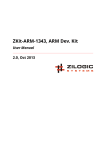
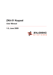
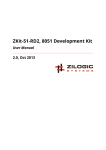
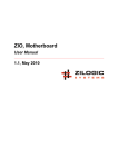
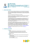
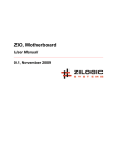
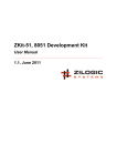
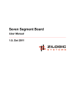
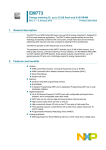
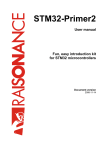
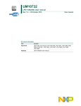
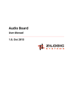
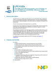
ZKit-ARM-1343, ARM Dev. Kit
User Manual
1.0, Sept 2011
ZKit-ARM-1343, ARM Dev. Kit User Manual
Rev. 1.0
This work is licensed under the Creative Commons Attribution-Share Alike 2.5 India License. To view a
copy of this license, visit http://creativecommons.org/licenses/by-sa/2.5/in/ or send a letter to Creative
Commons, 171 Second Street, Suite 300, San Francisco, California, 94105, USA.
ZKit-ARM-1343, ARM Dev. Kit User Manual
Rev. 1.0
Table of Contents
1. Introduction ............................................................................................................................ 1
1. Features ........................................................................................................................ 1
2. Applications ................................................................................................................... 1
3. Board Details ................................................................................................................. 1
2. Board Design ......................................................................................................................... 2
1. Overview ....................................................................................................................... 2
2. Locating Components ..................................................................................................... 2
3. Power Supply ................................................................................................................ 3
4. CPU .............................................................................................................................. 3
5. LCD Display .................................................................................................................. 4
6. I²C EEPROM ................................................................................................................. 5
7. Debug LEDs .................................................................................................................. 5
8. Keypad .......................................................................................................................... 5
3. Connectors ............................................................................................................................ 7
1. SPI Pinmap ................................................................................................................... 7
2. UART-I2C Pinmap ......................................................................................................... 7
3. DIO Pinmap ................................................................................................................... 8
4. J1 Proto Header Pinmap ................................................................................................ 9
5. J2 Proto Header ........................................................................................................... 10
A. Legal Information ................................................................................................................. 11
1. Copying ....................................................................................................................... 11
2. Disclaimers .................................................................................................................. 11
Zilogic Systems
Page iii
ZKit-ARM-1343, ARM Dev. Kit User Manual
Rev. 1.0
Chapter 1. Introduction
ZKit-ARM-1343 is a ARM micro-controller development kit from Zilogic Systems. ZKit-ARM-1343 is
designed for a easy usage, rapid prototyping and product design. ZKit-ARM-1343 is a single board
computer which can be used as it is in the end product design.
1. Features
The ZKit-ARM-1343 comes with
• Graphics display and on-board keys
• Well defined IO connector interface for I²C, SPI, GPIO and SIO
• USB and External power supply
• Programmable through USB
• Free and open source compiler and programmer
• Zilogic’s open source software library
• Ready to go with Zilogic’s Relay, Motor, Display boards etc., add-on boards.
2. Applications
• CPU for embedded products
• Embedded application prototyping
• Teaching and learning embedded systems
3. Board Details
The ZKit-ARM-1343 offers the following features:
• NXP LPC1343 micro-controller with 32KB Flash and 8KB RAM
• 12MHz crystal
• On-board Peripherals
– 128x64 graphics LCD, with backlight
– 2K I²C EEPROM
– 5 ADC channels
– USB mass storage interface for code download
– Five button keypad
– 2 debug LEDs
• Connectors
– USB-mini, type B connector
– 14 pin header for Digital IO
– 10 pin header for UART and I²C
– 10 pin header for SPI
– 10x2 pin header for ADC and PWM
Zilogic Systems
Page 1
ZKit-ARM-1343, ARM Dev. Kit User Manual
Rev. 1.0
Chapter 2. Board Design
1. Overview
A bird’s eye view of the devices available on the board, is shown in the following block diagram. Each
device connectivity is described in detail in the following sections.
Figure 2.1. Block Diagram
2. Locating Components
The location of the components on the board is indicated in the following diagram.
Zilogic Systems
Page 2
ZKit-ARM-1343, ARM Dev. Kit User Manual
Rev. 1.0
Figure 2.2. Front View
3. Power Supply
The ZKit-ARM-1343 can be powered from a PC USB port, or an external power supply with USB-mini
connector.
The external power supply, if used, should be a regulated power supply. The regulated power supply
should have the following charactersitcs.
Output Voltage
5V
Output Current
> 500mA
Connector
USB-mini
4. CPU
The heart of the ZKit-ARM-1343 is a NXP LPC1343 micro-controller. The LPC1343 is an 32-bit
ARM 3.3V low power micro-controller with 32KB Flash, 8KB of data RAM and supports In-System
Programming (ISP).
The main features of the micro-controller are listed below.
• ARM Cortex-M3 processor, running at frequencies of up to 72 MHz.
• 32 kB on-chip flash programming memory.
• 8 kB SRAM.
• In-System Programming (ISP) and In-Application Programming (IAP) via on-chip bootloader
software.
• Selectable boot-up: UART or USB.
• USB MSC and HID on-chip drivers.
• Serial interfaces:
Zilogic Systems
Page 3
ZKit-ARM-1343, ARM Dev. Kit User Manual
Rev. 1.0
– USB 2.0 full-speed device controller with on-chip PHY for device.
– UART with fractional baud rate generation, modem, internal FIFO, and RS-485/EIA-485
support.
– SSP controller with FIFO and multi-protocol capabilities.
– I²C-bus with Fast-mode Plus with a data rate of 1 Mbit/s.
• Up to 42 General Purpose I/O (GPIO) pins with configurable pull-up/pull-down resistors.
• Four general purpose counter/timers with a total of four capture inputs and 13 match outputs.
• Programmable WatchDog Timer (WDT).
• System tick timer.
• Three reduced power modes: Sleep, Deep-sleep, and Deep power-down.
• Single power supply 3.3V.
• 10-bit ADC with input multiplexing among 8 pins.
• GPIO pins can be used as edge and level sensitive interrupt sources.
• Processor wake-up from Deep-sleep mode via a dedicated start logic using up to 40 of the
functional pins.
• Power-On Reset (POR).
• System PLL allows CPU operation up to the maximum CPU rate without the need for a highfrequency crystal.
• Code Read Protection (CRP) with different security levels.
• Unique device serial number for identification.
• Available as 48-pin LQFP package and 33-pin HVQFN package.
4.1. In-System Programming (ISP)
Firmware upgradation can be done through USB interface. LPC1343 includes a built-in USB bootloader
that allows to enumerate the ZKit-ARM-1343 board as a Mass Storage Device. With the USB bootloader,
the compiled binary file can be dragged and dropped on to the device, just like with any other USB
memory stick.
To program the firmware, press the PROG button. This causes the microcontroller to enter ISP mode.
The firmware can then be copied on to the drive corresponding to the microcontroller. To execute the
programmed firmware, press the RESET button.
5. LCD Display
The ZKit-ARM-1343 has a TM12864, Sitronix chipset compatible, 128x64 pixel monochrome LCD. The
LCD is connected to SPI lines of the MCU. The following diagram shows the LCD pin connection details.
Figure 2.3. LCD Connection Diagram
Zilogic Systems
Page 4
ZKit-ARM-1343, ARM Dev. Kit User Manual
Rev. 1.0
6. I²C EEPROM
The ZKit-ARM-1343 has a CAT24AA02 EEPROM for data storage. The CAT24AA02 is a 2-Kbit Serial
EEPROM. The memory is accessed via I²C bus. The maximum bus speed supported by the device is
400 kbit/s
The I²C EEPROM is connected to the on-chip I²C controller of the LPC1343 MCU. The following diagram
shows the EEPROM pin connection details.
Figure 2.4. I²C EEPROM Connection Diagram
7. Debug LEDs
The ZKit-ARM-1343 has two debug LEDs connected to PIO3_0 and PIO0_7, through a non-inverting
buffer. By driving PIO3_0 and PIO0_7 high, the LEDs can be switched On.
Figure 2.5. LEDs Connection Diagram
8. Keypad
The ZKit-ARM-1343 has 4 tactile push button switches connected to PIO1_11, PIO2_8, PIO2_9,
PIO2_10 and PIO2_11. The keypad connection details are shown in the following diagram.
Zilogic Systems
Page 5
ZKit-ARM-1343, ARM Dev. Kit User Manual
Rev. 1.0
Figure 2.6. Keypad Connection Diagram
Zilogic Systems
Page 6
ZKit-ARM-1343, ARM Dev. Kit User Manual
Rev. 1.0
Chapter 3. Connectors
This chapter describes the connectors in the ZKit-ARM-1343.
1. SPI Pinmap
The SPI header is terminated with serial peripheral interface (SPI) bus, 4 general purpose IO and power
supply. Add-on boards with SPI interface and general purpose IOs like MMC/SD card,EEPROM etc.,
can be connected through this header.
Table 3.1. SPI Header
Pin #
Header Signal MCU Signal
1
VCC
-
+5V
2
SCK
PIO0_10/SCK
TTL Out
3
MISO
PIO0_8/MISO
TTL In
4
MOSI
PIO0_9/MOSI
TTL Out
5
SS
PIO0_2/SSEL
TTL Out
6
DIO0
PIO3_0
TTL In/Out
1
7
DIO1
PIO3_1
TTL In/Out
1
8
DIO2
PIO3_2
TTL In/Out
1
9
DIO3
PIO3_3
TTL In/Out
1
10
GND
-
Ground
1
Signal Type
1
5V tolerant Input
VCC (Pin 1)
This is the +5V power supply for the external devices. The supply has a total
current limit of 200mA when powered through USB.
SCK (Pin 2)
This is Serial Clock signal.
MISO (Pin 3)
This is the Master Input, Slave Output signal.
MOSI (Pin 4)
This is the Master Output, Slave Input signal.
SS (Pin 5)
This is the SPI chip select signal.
DIO (Pin 6-9)
These are digital input/output signals. These lines can be used to interface
any extra signals required for a SPI devices like SD Card, etc., or can be
used as chip selects for four other devices.
GND (Pin 10)
This is the ground signal. All other signals are referenced to the this signal.
2. UART-I2C Pinmap
The UART-I2C header is terminated with serial communication signals, I²C signals and power supply.
Add-on boards, with different functionalities, can be connected through this header.
Zilogic Systems
Page 7
ZKit-ARM-1343, ARM Dev. Kit User Manual
Rev. 1.0
Table 3.2. UART-I2C Header
Pin #
Header Signal MCU Signal
1
VCC
-
+5V
2
RXD
PIO1_6/RXD
TTL In
3
TXD
PIO1_7/TXD
TTL Out
4
SCL
PIO0_4/SCL
OC
2
5
SDA
PIO0_5/SDA
OC
2
6
DIO0
PIO1_5
TTL In/Out
1
7
DIO1
PIO0_7
TTL In/Out
1
8
DIO2
PIO2_0
TTL In/Out
1
9
DIO3
PIO0_11
TTL In/Out
1
10
GND
-
Ground
1
5V tolerant input
2
Open collector, with 3.3V pull-up
Signal Type
1
VCC (Pin 1)
This is the +5V power supply for the external devices. The supply
has a total current limit of 200mA when powered through USB.
RXD (Pin 2)
This is receive line of serial IO.
TXD (Pin 3)
This is transmit line of serial IO.
SCL, SDA (Pin 4, 5)
These are I²C bus signals(clock, data), and can be used to connect
I²C devices. The signals are pulled up to 3.3V, through a 4.7K
resistor.
DIO (Pin 6-9)
These are digital input/output signals. These pins can be used for
hand-shake and flow control signals like DTR, RTS, CTS, etc.
GND (Pin 10)
This is the ground signal. All other signals are referenced to this
signal.
3. DIO Pinmap
The DIO header is terminated with port PIO2 signals, along with power supply. Add-on boards, with
different functionalities, can be connected through this header.
Table 3.3. DIO Header
Pin #
Header Signal MCU Signal
Signal Type
1
VCC
-
+5V
2
DIO0
PIO2_0
TTL In/Out
1
Zilogic Systems
Page 8
ZKit-ARM-1343, ARM Dev. Kit User Manual
Rev. 1.0
Pin #
Header Signal MCU Signal
Signal Type
3
DIO1
PIO2_1
TTL In/Out
1
4
DIO2
PIO2_2
TTL In/Out
1
5
DIO3
PIO2_3
TTL In/Out
1
6
DIO4
PIO2_4
TTL In/Out
1
7
DIO5
PIO2_5
TTL In/Out
1
8
DIO6
PIO2_6
TTL In/Out
1
9
DIO7
PIO2_7
TTL In/Out
1
10
DIO8
PIO2_8
TTL In/Out
1
11
DIO9
PIO2_9
TTL In/Out
1
12
DIO10
PIO2_10
TTL In/Out
1
13
DIO11
PIO2_11
TTL In/Out
1
14
GND
-
Ground
1
5V tolerant input
VCC (Pin 1)
This is the +5V power supply for the external devices. The supply has a
total current limit of 200mA when powered through USB.
DO (Pin 2-9)
These are digital output signals. The signal is a 5V logic signal, but the
output can drive a 5V device or 3.3V device with 5V tolerance. These
signals are pulled up to 5V, through a 4.7K resistor since P0 port does
not have internal pull up.
DIO (Pin 10-13)
These are digital input/output signals. The signal is a 5V logic signal, but
the output can drive a 5V device or 3.3V device with 5V tolerance. These
signals can be used as control and hand-shake signals.
GND (Pin 14)
This is the ground signal. All other signals are referenced to this signal.
4. J1 Proto Header Pinmap
The J1 Proto Header provides the signals available on the FRC-ports, through a socket header, for
quick prototyping, using bread-boards and single strand wires. For the signal descriptions, refer to the
corresponding FRC header.
Table 3.4. J1 Proto Header
Pin #
Header Signal MCU Signal
Signal Type
1
VCC
-
+5V
2
RXD
PIO1_6/RXD
TTL In
3
TXD
PIO1_7/TXD
TTL Out
4
SCL
PIO0_4/SCL
OC
2
5
SDA
PIO0_5/SDA
OC
2
6
DIO0
PIO1_5
TTL In/Out
1
7
DIO1
PIO0_7
TTL In/Out
1
8
DIO2
PIO2_0
TTL In/Out
1
9
DIO3
PIO0_11
TTL In/Out
1
10
SCK
PIO0_10/SCK
TTL Out
11
MISO
PIO0_8/MISO
TTL In
12
MOSI
PIO0_9/MOSI
TTL Out
13
SS
PIO0_2/SSEL
TTL Out
1
1
Zilogic Systems
Page 9
ZKit-ARM-1343, ARM Dev. Kit User Manual
Rev. 1.0
Pin #
Header Signal MCU Signal
Signal Type
14
DIO0
PIO3_0
TTL In/Out
1
15
DIO1
PIO3_1
TTL In/Out
1
16
DIO2
PIO3_2
TTL In/Out
1
17
DIO3
PIO3_3
TTL In/Out
1
18
DIO0
PIO2_0
TTL In/Out
1
19
DIO1
PIO2_1
TTL In/Out
1
20
DIO2
PIO2_2
TTL In/Out
1
21
DIO3
PIO2_3
TTL In/Out
1
22
DIO4
PIO2_4
TTL In/Out
1
23
DIO5
PIO2_5
TTL In/Out
1
24
DIO6
PIO2_6
TTL In/Out
1
25
DIO7
PIO2_7
TTL In/Out
1
26
GND
-
Ground
1
5V tolerant input
2
Open collector, with 3.3V pull-up
5. J2 Proto Header
The J2 Proto Header provides ADC and PWM signals through a socket header. The 10 signals are
made available through a 20 pin header, with each signal duplicated on two pins.
Table 3.5. J1 Proto Header
Pin #
MCU Signal
ADC
Capture/Match
1
3.3V
-
-
2
PIO1_0
AD1
CT32B1_CAP0
3
PIO1_1
AD2
CT32B1_MAT0
4
PIO1_2
AD3
CT32B1_MAT1
5
PIO1_2
AD4
CT32B1_MAT2
6
PIO1_4
AD5
CT32B1_MAT3
7
PIO1_5
-
CT32B0_CAP0
8
PIO1_6
-
CT32B0_MAT0
9
PIO1_7
-
CT32B0_MAT1
10
GND
-
-
Zilogic Systems
Page 10
ZKit-ARM-1343, ARM Dev. Kit User Manual
Rev. 1.0
Appendix A. Legal Information
1. Copying
This work is licensed under the Creative Commons Attribution-Share Alike 2.5 India License. To view a
copy of this license, visit http://creativecommons.org/licenses/by-sa/2.5/in/ or send a letter to Creative
Commons, 171 Second Street, Suite 300, San Francisco, California, 94105, USA.
2. Disclaimers
NO WARRANTY. ZILOGIC SYSTEMS' DEVELOPMENT KITS (AND TECHNICAL SUPPORT,
IF ANY) ARE PROVIDED "AS IS" AND WITHOUT ANY WARRANTY OF ANY KIND, EXPRESS
OR IMPLIED. TO THE MAXIMUM EXTENT PERMITTED UNDER APPLICABLE LAWS, ZILOGIC
SYSTEMS EXPRESSLY DISCLAIMS ALL WARRANTIES, EXPRESS OR IMPLIED, INCLUDING
BUT NOT LIMITED TO IMPLIED WARRANTIES OF MERCHANTABILITY, FITNESS FOR A
PARTICULAR PURPOSE, AND NONINFRINGEMENT. ZILOGIC SYSTEMS DOES NOT WARRANT
THAT THE FUNCTIONS CONTAINED IN ZILOGIC SYSTEMS' DEVELOPMENT KITS WILL
MEET YOUR REQUIREMENTS, OR THAT THE OPERATION WILL BE UNINTERRUPTED OR
ERROR-FREE, OR THAT DEFECTS IN ZILOGIC SYSTEMS' DEVELOPMENT KITS WILL BE
CORRECTED. FURTHERMORE, ZILOGIC SYSTEMS DOES NOT WARRANT OR MAKE ANY
REPRESENTATIONS REGARDING THE USE OR THE RESULTS OF THE USE OF THE
ZILOGIC SYSTEMS' DEVELOPMENT KITS IN TERMS OF THEIR CORRECTNESS, ACCURACY,
RELIABILITY, OR OTHERWISE. SOME JURISDICTIONS DO NOT ALLOW THE EXCLUSION OF
IMPLIED WARRANTIES, SO THE ABOVE EXCLUSION MAY NOT APPLY OR MAY BE LIMITED.
Limitation of Liability. Zilogic Systems' development kits are not designed, authorized or warranted
to be suitable for use in medical, military, aircraft, space or life support equipment, not in applications
where failure or malfunction of a Zilogic Systems product can resonably be expected to result in
personal injury, death or severe property or environmental damage. Zilogic Systems accepts no liability
for inclusion and/or use of Zilogic Systems' development kits in such equipment or applications and
therefore such inclusion and/or use is at the customer’s own risk.
Zilogic Systems
Page 11