1
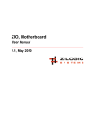
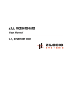
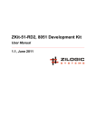
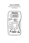
Seven Segment Board
User Manual
1.0, Oct 2011
Seven Segment Board User Manual
Rev. 1.0
This work is licensed under the Creative Commons Attribution-Share Alike 2.5 India License. To view a
copy of this license, visit http://creativecommons.org/licenses/by-sa/2.5/in/ or send a letter to Creative
Commons, 171 Second Street, Suite 300, San Francisco, California, 94105, USA.
Seven Segment Board User Manual
Rev. 1.0
Table of Contents
1. Seven segment board ............................................................................................................
1. Overview .......................................................................................................................
2. Features ........................................................................................................................
3. Applications ...................................................................................................................
4. Locating components .....................................................................................................
5. Power Supply ................................................................................................................
6. Connectivity ...................................................................................................................
7. Algorithm .......................................................................................................................
Zilogic Systems
1
1
1
1
1
1
1
2
Page iii
Seven Segment Board User Manual
Rev. 1.0
Chapter 1. Seven segment board
1. Overview
Seven segment display board has 8 seven segment LEDs. It can be used as a display device for
displaying decimal numerals as an alternative for more complex dot-matrix displays.
This multiplexed display board has a built-in decoder needs only 3 control lines to select the required
digit and 8 data lines shared to all 7segments. All segments including decimal points are available for
control, so that customized readout is made possible. The TTL compatible inputs allows this board work
with most micro-controllers and control systems.
2. Features
• Standard 0.56" 7-Segment LED Display
• 8 Digits for counter/timer applications
• Supports decimal point
• Powered from motherboard via FRC header
• TTL compatible inputs
• Standard 0.1" FRC header for connection to control logic/MCU
• Ready to go with Zilogic mother boards.
3. Applications
• Digital clocks and calendars.
• Electronic meters
• Weighing machines
• Currency displays
• and other numerical digital read-outs.
4. Locating components
Below diagram explains the location of components on the board
Figure 1.1. Front View
5. Power Supply
The seven segment display board is powered by the motherboard using a FRC-14 connector. The 1st
and 14th pin is connected to VCC and GND respectively.
6. Connectivity
The seven segment display board can be interfaced to the mother board using a FRC-14 connector.
The connection details are explained in the below diagram.
Zilogic Systems
Page 1
Seven Segment Board User Manual
Rev. 1.0
The SEG pins are used to drive the value to be displayed on a 7-segment and the DSEL used to select
the digit position on which the value has to be displayed.
Figure 1.2. Signal connection diagram
Table 1.1. header to display signal mapping table
Pin# Motherboard Display
Pin#
Motherboard
Display
1
VCC
VCC
8
DIO_6
SEG G
2
DIO_0
SEG A
9
DIO_7
SEG H
3
DIO_1
SEG B
10
DIO_8
DSEL 0
4
DIO_2
SEG C
11
DIO_9
DSEL 1
5
DIO_3
SEG D
12
DIO_10
DSEL 2
6
DIO_4
SEG E
13
DIO_11
DISPON#
7
DIO_5
SEG F
14
GND
GND
7. Algorithm
Since the signals that drive the segments are shared by the 8 displays, the segments of only one display
can be driven at a time. Each display is turned on successively for a small period of time (1.5ms, to
avoid flicker), and by persistence of vision all of them appear to be on simultaneously.
Persistence of vision is the phenomenon of the eye by which even nanoseconds of
exposure to an image result in milliseconds of sight. — Wikipedia.org
—
7.1. Selecting a digit on the board
A digit of the seven segment display board can be selected by using three control lines DSEL 0, DSEL
1 and DSEL 2. Below table explains how to select a digit using the 3 control lines
Table 1.2. Digit Selection
DSEL0 DSEL1
DSEL2
DIGIT-NO
0
0
0
DIGIT 1
0
0
1
DIGIT 2
0
1
0
DIGIT 3
Zilogic Systems
Page 2
Seven Segment Board User Manual
DSEL0 DSEL1
DSEL2
DIGIT-NO
0
1
1
DIGIT 4
1
0
0
DIGIT 5
1
0
1
DIGIT 6
1
1
0
DIGIT 7
1
1
1
DIGIT 8
Rev. 1.0
7.2. 7-Segment Display
The algorithm for displaying a 7-segment digit is given below.
1. Turn off all the 7-segment displays.
2. Turn on/off segments by driving the segment signals (SEGx). The segment signals to be driven
for each hexadecimal digit is given in the following table.
3. Select the 7-segment display by driving one of DIGIT1, DIGIT2,
i. DIGIT8
Character
SEG[A:H]
0
0x3F
1
0x06
2
0x5B
3
0x4F
4
0x66
5
0x6D
6
0x7D
7
0x07
8
0x7F
9
0x67
The MSB of segment signals (7th bit) is used to switch on the dot separator.
7.3. Multiplexed 7-segment Display
The algorithm for displaying multiple 7-segment digits simultaneously is given below.
a. select the 7-segment
b. Turn off leds in the selected 7-segment.
c. Drive the segment data pins corresponding to the value to be displayed.
d. Generate a 1.5ms delay using a timer.
e. select next digit
f. Goto step b.
Zilogic Systems
Page 3