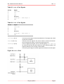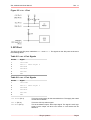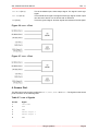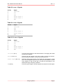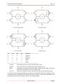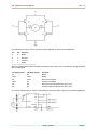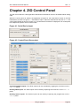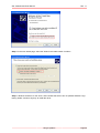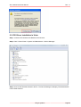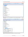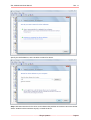
1
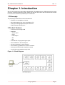
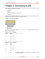
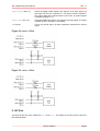
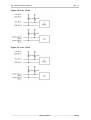
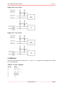
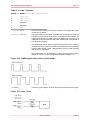
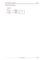
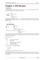
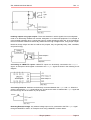
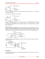
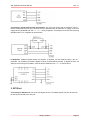
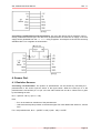
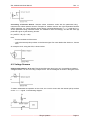
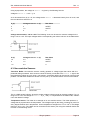
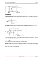
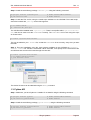
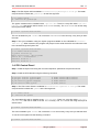
ZIO, Motherboard
User Manual
1.1, May 2010
ZIO, Motherboard User Manual
Rev. 1.1
This work is licensed under the Creative Commons Attribution-Share Alike 2.5 India License. To view a
copy of this license, visit http://creativecommons.org/licenses/by-sa/2.5/in/ or send a letter to Creative
Commons, 171 Second Street, Suite 300, San Francisco, California, 94105, USA.
ZIO, Motherboard User Manual
Rev. 1.1
Table of Contents
1. Introduction ............................................................................................................................ 1
1. Philosophy ..................................................................................................................... 1
2. Product Features ............................................................................................................ 1
2. Connecting to ZIO .................................................................................................................. 2
1. GPIO Port ...................................................................................................................... 2
2. I2C Port ......................................................................................................................... 3
3. SPI Port ........................................................................................................................ 5
4. Sensor Port ................................................................................................................... 6
5. PWM Port ...................................................................................................................... 9
3. ZIO Recipes ......................................................................................................................... 12
1. GPIO Port .................................................................................................................... 12
2. I2C Port ....................................................................................................................... 14
3. SPI Port ....................................................................................................................... 15
4. Sensor Port .................................................................................................................. 16
5. PWM Port .................................................................................................................... 19
4. ZIO Control Panel ................................................................................................................ 22
5. Software Installation ............................................................................................................. 24
1. Under GNU/Linux ......................................................................................................... 24
2. Under Windows ............................................................................................................ 27
6. Legal Information ................................................................................................................. 35
1. Copying ....................................................................................................................... 35
2. Disclaimers .................................................................................................................. 35
Zilogic Systems
Page iii
ZIO, Motherboard User Manual
Rev. 1.1
Chapter 1. Introduction
ZIO is a IO framework for rapid product development. ZIO Motherboard is a USB device that provides
access to IO interfaces like GPIO, ADC, PWM, I2C and SPI. ZIO comes with an API that can be used
to access the IO interfaces provided by the motherboard.
1. Philosophy
The philosophy behind ZIO can be summarised as:
• Extend the IO capabilities of the PC.
• Move development from micro-controllers to PC
• Use high level languages like Python and Java.
• Rapid prototype development.
2. Product Features
• Connects to PC through USB
• Interfaces
– Sensor Input
– GPIO
– PWM Output
– SPI
– I2C
• Host-side API for programming the ports
• APIs available for Java and Python
• API documentation for easy reference
• Port interfacing guidelines for common scenarios
• GUI based Control Panel to explore the board
• On-field firmware upgrade through USB
Figure 1.1. Block Diagram
Zilogic Systems
Page 1
ZIO, Motherboard User Manual
Rev. 1.1
Chapter 2. Connecting to ZIO
In this chapter we will describe the connector used for the ZIO ports and the pins found on each of the
ports. The ZIO has 4 different types of ports.
1. GPIO Port
2. I2C Port
3. SPI Port
4. Sensor Port (Marked as AIN on the ZIO)
5. PWM Port
All the ports are available through RJ12 jacks. The RJ12 is similar to RJ11, but has six pins. The RJ12
jack pins and pin numbering are shown in the following diagram.
Figure 2.1. RJ12 Jack (Female)
1. GPIO Port
The ZIO has two GPIO ports, marked as GPIO-0 and GPIO-1. The signals on the GPIO ports are
shown in the following tables.
Table 2.1. GPIO-0 Signals
Pin No.
Signal
1
+5V Power
2
GPIO Output 0
3
GPIO Output 1
4
GPIO Input 0
5
GPIO Input 1
6
GND
Table 2.2. GPIO-1 Signals
Pin No.
Signal
1
+5V Power
2
GPIO Output 2
3
GPIO Output 3
4
GPIO Input 2
5
GPIO Input 3
6
GND
+5V Power (Pin 1)
This is the power supply for the external device. The supply has a total
current limit of 200mA.
Zilogic Systems
Page 2
ZIO, Motherboard User Manual
Rev. 1.1
GPIO Output (Pin 2, 3)
These are digital output signals. The signal is a 5V logic signal, but
the output can drive a 5V device or 3.3V device with 5V tolerance.
The output signal has a series resistor of 270 ohm, to protect against
accidental shorting to GND.
GPIO Input (Pin 4, 5)
These are digital input signals. The signal is a 5V logic signal. The signal
is pulled up to 5V, through a 4.7K resistor.
GND (Pin 6)
This is the ground signal. All other signals are referenced to the this
signal.
Figure 2.2. GPIO-0 Port
Figure 2.3. GPIO-1 Port
2. I2C Port
The ZIO has two I2C ports, marked as I2C-0 and I2C-1. The signals on the I2C ports are shown in
the following tables.
Zilogic Systems
Page 3
ZIO, Motherboard User Manual
Rev. 1.1
Table 2.3. I2C-0 Port Signals
Pin No.
Signal
1
+5V Power
2
SCL
3
SDA
4
Reserved
5
Interrupt / GPIO Input 4
6
GND
Table 2.4. I2C-1 Port Signals
Pin No.
Signal
1
+5V Power
2
SCL
3
SDA
4
Reserved
5
Interrupt / GPIO Input 4
6
GND
+5V Power (Pin 1)
This is the power supply for the external devices. The supply has a total
current limit of 200mA.
SCL, SDA (Pin 2, 3)
These are I2C bus signals, and can be used to connect I2C devices.
Any 5V tolerant I2C device, can be connected to the bus.
Interrupt (Pin 5)
This is a digital input signal. This is a shared signal (GPIO Input 4)
for all I2C devices and should be driven by open collector outputs. The
signal is pulled up to 5V, through a 10K resistor.
GND (Pin 6)
This is the ground signal. All other signals are referenced to this signal.
Figure 2.4. I2C-0 Port
Zilogic Systems
Page 4
ZIO, Motherboard User Manual
Rev. 1.1
Figure 2.5. I2C-1 Port
3. SPI Port
The ZIO has two SPI ports, marked as SPI-0 and SPI-1. The signals on the SPI ports are shown in
the following tables.
Table 2.5. SPI-0 Port Signals
Pin No.
Signal
1
+5V Power
2
SPI CS / GPIO Output 4
3
SPI MOSI
4
SPI MISO
5
SPI CLK
6
GND
Table 2.6. SPI-1 Port Signals
Pin No.
Signal
1
+5V Power
2
SPI SS / GPIO Output 5
3
SPI MOSI
4
SPI MISO
5
SPI SCK
6
GND
+5V Power (Pin 1)
This is the power supply for the external devices. The supply has a total
current limit of 200mA.
SPI SS (Pin 2)
This is the SPI chip select signal.
SPI MOSI (Pin 3)
This is the Master Output, Slave Input signal. The signal is a 5V logic
signal, but the output can drive a 5V device or 3.3V device with 5V
tolerance.
Zilogic Systems
Page 5
ZIO, Motherboard User Manual
Rev. 1.1
SPI MISO (Pin 4)
This is the Master Input, Slave Output signal. The signal is a 5V logic
signal.
SPI SCK (Pin 5)
This is Serial Clock signal. The signal is a 5V logic signal, but the output
can drive a 5V device or 3.3V device with 5V tolerance.
GND (Pin 6)
This is the ground signal. All other signals are referenced to this signal.
Figure 2.6. SPI-0 Port
Figure 2.7. SPI-1 Port
4. Sensor Port
The ZIO has four sensor ports, marked as AIN-0, AIN-1, AIN-2 and AIN-3. The signals on the sensor
ports are shown in the following table.
Table 2.7. AIN-0 Signals
Pin No.
Signal
1
+5V Power
2
SCL
3
SDA
4
Sensor Input 0
5
Sensor Input 1
6
GND
Zilogic Systems
Page 6
ZIO, Motherboard User Manual
Rev. 1.1
Table 2.8. AIN-1 Signals
Pin No.
Signal
1
+5V Power
2
SCL
3
SDA
4
Sensor Input 2
5
Sensor Input 3
6
GND
Table 2.9. AIN-2 Signals
Pin No.
Signal
1
+5V Power
2
SCL
3
SDA
4
Sensor Input 4
5
Sensor Input 5
6
GND
Table 2.10. AIN-3 Signals
Pin No.
Signal
1
+5V Power
2
SCL
3
SDA
4
Sensor Input 6
5
Sensor Input 7
6
GND
+5V Power (Pin 1)
This is the power supply for the external sensors. The supply has a total
current limit of 200mA.
SCL, SDA (Pin 2, 3)
These are I2C bus signals, and can be used to connect I2C devices.
Any 5V tolerant I2C device, can be connected to the bus.
Sensor Input (Pin 4, 5)
These are analog input signals. The signals are connected to a 10-bit
ADC. The input signal range is 0 to 3V. The input is translated to a value
in the range 0 to 1023, by the ADC. The pins are connected to a 3V
reference through 10K pull up resistors.
GND (Pin 6)
This is the ground signal. All other signals are referenced to this signal.
Zilogic Systems
Page 7
ZIO, Motherboard User Manual
Rev. 1.1
Figure 2.8. AIN-0 Port
Figure 2.9. AIN-1 Port
Zilogic Systems
Page 8
ZIO, Motherboard User Manual
Rev. 1.1
Figure 2.10. AIN-2 Port
Figure 2.11. AIN-3 Port
5. PWM Port
The ZIO has two PWM ports, marked as PWM-0 and PWM-1. The signals on the PWM ports are shown
in the following tables.
Table 2.11. PWM-0 Signals
Pin No.
Signal
1
+5V Power
2
PWM Output 0
3
PWM Output 1
4
Reserved
5
Reserved
6
GND
Zilogic Systems
Page 9
ZIO, Motherboard User Manual
Rev. 1.1
Table 2.12. PWM-1 Signals
Pin No.
Signal
1
+5V Power
2
PWM Output 2
3
PWM Output 3
4
Reserved
5
Reserved
6
GND
+5V Power (Pin 1)
This is the power supply for the external sensors. The supply has a total
current limit of 200mA.
PWM Output (Pin 2, 3)
These are PWM output signals. The PWM signal when active produces
a stream of pulses whose width can be controlled through software. An
important parameter of a PWM signal is the duty cycle. The duty cycle
is defined as the ratio between the pulse duration and pulse period of
a rectangular waveform.
The PWM signal can be used to control the power delivered to a load, by
controlling the duty cycle of the PWM signal. PWM signals are generally
used for Motor speed control, LED brightness control, power supplies
and wave form generation.
The PWM signal is a 5V CMOS/TTL output. The signal has a series
resistor of 270 ohm, to protect against accidental shorting to GND.
Figure 2.12. PWM signals with various pulse widths
GND (Pin 6)
This is the ground signal. All other signals are referenced to this signal.
Figure 2.13. PWM-0 Port
Zilogic Systems
Page 10
ZIO, Motherboard User Manual
Rev. 1.1
Figure 2.14. PWM-1 Port
Zilogic Systems
Page 11
ZIO, Motherboard User Manual
Rev. 1.1
Chapter 3. ZIO Recipes
1. GPIO Port
Connecting LEDs. Connect the anode of the LED to an Output signal, and the cathode to GND.
The built-in series resistor is sufficient to limit the current.
Connecting series of LEDs. Since the Output signal can not provide sufficient power for more than
one LED, and external power source is to be used. And the power supply can be controlled using a
MOSFET switch.
The circuit diagram for connecting a series of LEDs is shown above. The following formula can be used
to calculate the resistance for the current limiting resistor. (The voltage drop across the MOSFET is
considered to be negligible.)
R = (Vcc - NVd) / Id
Where,
Vd
Voltage Drop Across LED
N
No. of LEDs
Id
Current for the required brightness
Vcc
LED supply voltage
R
Current Limiting Resistor
As an example, for the following parameters,
• Vcc = 12V
• Id = 11mA
• N=4
the calculated current limiting resistance is 470 ohms.
Connecting relays. Relays are used to control a high-voltage/high-current circuit with a low-voltage/
low-current signal. A relay can be connected to the ZIO through a MOSFET as shown in the following
circuit diagram.
Zilogic Systems
Page 12
ZIO, Motherboard User Manual
Rev. 1.1
Isolating outputs using opto-coupler. There are situations in which signals from one subsystem
need to be electrically isolated from another subsystem in an electrical equipment. For example, a
microcontroller operating at 5V, controls the power to a load operating at 230V AC. In such situations,
the microcontroller needs to be electrically isolated from the high voltage section, using a opto-coupler.
Note that, though relays can also be used for this purpose, they are generally bulky, slow, unreliable,
and power hungry.
Connecting to CMOS/TTL inputs. CMOS/TTL inputs can be directly connected to the Output
signal. An example of shift register connected to the Output signals is shown in the following circuit
diagram.
Connecting Switches. Switches can be directly connected between the Input and GND. When the
switch is pressed the Input signal will be low, and when the switch is released the Input signal will
be become high due to the built-in in pull-up resistor.
Detecting External Voltage. Any external voltage input can be connected to the ZIO Input signal
through a MOSFET or a BJT. An example circuit using a MOSFET is shown below.
Zilogic Systems
Page 13
ZIO, Motherboard User Manual
Rev. 1.1
If the input voltage (Vs) is greater than the threshold voltage of the MOSFET, the Input signal will be
low, or else it will be high.
An example circuit using a BJT is shown below.
If the input current (Is) is greater than (It = 0.5mA / hFE), the Input signal will be low, or else it will
be high. For all practical purposes, a (It = 1mA) input current is sufficient to make the Input signal
go low. The base resistance (Rb) has to be chosen to make the Input signal low, when the required
input voltage is driven.
Rb = (Vs - Vbe) / It
Connecting an Analog Comparator. An analog comparator can be used to identify if the input
voltage is larger than a specified reference voltage. Any operational amplifier can be used as a
comparator, but a dedicated comparators like LM339 which provide open collector CMOS/TTL outputs
are suitable for interfacing with logic circuits. An example circuit is shown in the following diagram.
Isolating inputs using opto-coupler. As in the case of outputs, inputs can also be electrically isolated
using opto-couplers.
2. I2C Port
Connecting 5V I2C devices. Since the I2C signal are pulled up to 5V, 5V I2C devices can be directly
connected to the I2C port.
Zilogic Systems
Page 14
ZIO, Motherboard User Manual
Rev. 1.1
Connecting 3.3V I2C devices with 5V tolerance. Any 3.3V I2C device with 5V tolerance can be
directly connected to the I2C port. The device can be powered from an external 3.3V supply, or the 3.3V
supply can be generated from the +5V Power using a regulator. An example circuit with the commonly
available LM1117-3.3 regulator is shown below.
IO Expander. Additional digital inputs and outputs, if required, can be obtained using a I2C IO
expander. The PCA8574 provides 8 digital I/O lines, and PCA8578 provides 16 digital I/O lines. An
example circuit using the PCA8574, with I2C device address set to 0x20, is shown below.
3. SPI Port
Connecting 5V SPI devices. Since the SPI signal are 5V TTL/CMOS signals, 5V SPI devices can
be directly connected to the SPI port.
Zilogic Systems
Page 15
ZIO, Motherboard User Manual
Rev. 1.1
Connecting 3.3V SPI devices with 5V tolerance. Any 3.3V SPI device with 5V tolerance can be
directly connected to the SPI port. The device can be powered from an external 3.3V supply, or the 3.3V
supply can be generated from the +5V Power using a regulator. An example circuit with the commonly
available LM1117-3.3 regulator is shown below.
4. Sensor Port
4.1. Resistive Sensors
Connecting a Potentiometer. The position of potentiometer can be sensed by connecting the
potentiometer to the sensor input as shown in the figure below. When the centre pin 2 of the
potentiometer is moved from pin 1 to pin 3, the raw value varies from 0 to Nmax. Where Nmax is given
by the following formula.
Nmax = (0xFFFF x Rmax) / (Rmax + 10K)
Here,
• Rmax is the maximum resistance of the potentiometer
• 10K is the internal pull up resistor on the Sensor signal. For more details refer Section 4, “Sensor
Port”.
For a 10K potentiometer, Nmax = (0xFFFF x 10K) / (10K + 10K) = 0x7FFF
Zilogic Systems
Page 16
ZIO, Motherboard User Manual
Rev. 1.1
Connecting a Resistive Sensor. Sensors whose resistance varies with the parameter being
measured are called resistive sensors. Examples of resistive sensors are Light Dependent Resistor
(LDR), thermistor, etc. These sensors can be directly connected between the Sensor signal and GND.
As the parameter being measured varies, the resistance varies accordingly, and the raw value (N)
produced is given by the following formula.
N = (0xFFFF x R) / (R + 10K)
Here,
• R is the resistance of the sensor
• 10K is the internal pull up resistor on the Sensor signal. For more details refer Section 4, “Sensor
Port”.
An example circuit, using the LDR, is shown below.
4.2. Voltage Sensors
Voltage measurement, -3V to +3V. Though the ADC input range is 0 to 3V, it is possible to measure
voltages between -3V and +3V using a simple circuit. The circuit diagram is shown in the figure below.
To better understand the operation of the circuit, the circuit is shown with the internal pull-up resistor
on the Sensor signal, in the following diagram.
Zilogic Systems
Page 17
ZIO, Motherboard User Manual
Rev. 1.1
Using superposition, the voltage at Sensor 0 is given by the following formula.
Voltage at Sensor 0 = 1.5V + Vi / 2
As Vi decreases from 3V to -3V, the voltage at the Sensor 0 decreases linearly from 3V to 0V, and
the raw value from 0xFFFF to 0.
Vi (V)
Voltage at Sensor 0 (V)
Raw Value
3
3
0xFFFF
0
1.5
0x7FFF
-3
0
0
Voltage measurement, -15V to +15V. The following circuit can be used to measure voltages in the
range -15V to +15V. The input voltages and the corresponding raw values is shown in the table below.
Vi (V)
Voltage at Sensor 0 (V)
Raw Value
15
3.0
0xFFFF
0
1.5
0x7FFF
-15
0.0
0
4.3. Non-resistive Sensors
Transistor Buffer. Non-resistive sensors usually generate a voltage signal that varies with the
parameter being measured. Such sensors cannot be directly connected to the Sensor N signal, due
the signal being pulled-up to 3V using a 10K resistor. A transistor buffer can be used to overcome this
problem. The transistor isolates the sensor from the pull-up. A transistor buffer circuit is shown below.
This is a PNP emitter follower, where the emitter voltage is almost equal to the base voltage. For a Vi
range of 0 to 4.4V, the voltage at Sensor 0 is (Vi + 0.6). To compensate for the added 0.6V, subtract
0.6 to the obtained voltage.
Temperature Sensor. The LM35 is an example of an non-resistive sensor. The LM35 produces a
voltage that is proportional to the temperature. The voltage output by the LM35, increases by 10mV for
o
o
every degree Celsius rise in temperature. As the temperature changes from 2 C to 150 C, the voltage
rises from 0V to 1.5V. The LM35 can be connected to the Sensor port using the transistor buffer and
is shown in the following circuit.
Zilogic Systems
Page 18
ZIO, Motherboard User Manual
Rev. 1.1
5. PWM Port
LED Brightness Control. An LED can be connected between the PWM N signal and GND as shown
in the following diagram. When the duty cycle is varied the LED brightness varies accordingly.
One Bit DAC. An analog output can be generated from the PWM signal, using a low pass filter circuit.
The low pass filter circuit with an op-amp buffer is shown in the following diagram.
If the analog output has a frequency of F, the PWM frequency should be much higher than F. The values
of R and C are given by the following formula.
RC = 1 / (2
F)
For an output frequency of 1kHz, choosing R = 4kohm, C = 0.04uF.
DC Motor Control. A DC motor's speed and direction of rotation can be controlled using the PWM
port. The DC motor has to be interfaced through a circuit called the H-Bridge. A simple H-Bridge
constructed using switches is shown in the following diagram. By controlling, the switches the motor
can be made to rotate forward, reverse, brake, and free run. The various switch states and their effect
on the motor is shown in the following table.
Zilogic Systems
Page 19
ZIO, Motherboard User Manual
Rev. 1.1
S1
S2
S3
S4
Function
0
0
0
0
Free-run
0
1
1
0
Reverse
1
0
0
1
Forward
0
1
0
1
Brake
1
0
1
0
Brake
Forward
The current to flows in one direction through the motor.
Reverse
The current flows in the opposite direction through the motor.
Brake
Applying same voltage to both the terminals, counters the back EMF produced by
the motor, and causes it to come to a sudden stop.
Free-run
Power is cut-off from the motor, and the motor free-runs and eventually stops.
To control the motor through digital signals, the switches are replaced by transistors / MOSFETs. Driver
ICs like the L298, that implement the H-Bridge can also be used for motor control applications. The
block diagram of one half of a L298 is shown in the following diagram.
Zilogic Systems
Page 20
ZIO, Motherboard User Manual
Rev. 1.1
By controlling the inputs, various functions can be selected, as shown in the table below.
In1
In2
Function
0
0
Brake
0
1
Reverse
1
0
Forward
1
1
Brake
When in Forward state or Reverse state, the speed of the motor can be controlled by driving the inputs
with a PWM signal
In1 (Duty Cycle)
In2 (Duty Cycle)
Function
0%
0%
Brake
100%
100%
Brake
0%
100%
Reverse, full speed
100%
0%
Forward, full speed
0%
X%
Reverse, speed proportional to duty cycle
X%
0%
Forward, speed proportional to duty cycle
A circuit for interfacing a DC motor to the PWM port using the L298, is shown in the following diagram.
Zilogic Systems
Page 21
ZIO, Motherboard User Manual
Rev. 1.1
Chapter 4. ZIO Control Panel
The ZIO Control Panel is a GUI application that allows most features of ZIO to be tested without writing
code.
When the control panel is started, the application prompts for the serial device name of the ZIO
motherboard, as show in Figure 4.1, “Serial Device Input”. Select the serial device and click on OK. The
control panel window as shown in Figure 4.2, “Control Panel Screenshot” is displayed. The control panel
has multiple sub-panels, one for each module.
Figure 4.1. Serial Device Input
Figure 4.2. Control Panel Screenshot
Controlling GPIO Outputs. The GPIO outputs can be controlled by toggling the check box on the
GPIO Out panel.
Reading GPIO Inputs. The GPIO inputs can be read by inspecting the check box on the GPIO In
panel.
Reading Sensor Inputs. The Sensor inputs can be read by inspecting the progress bar on the
Sensor panel.
Zilogic Systems
Page 22
ZIO, Motherboard User Manual
Rev. 1.1
Controlling PWM Outputs. PWM signals can generated using the controls in the PWM panel,
1. Select the PWM channels, by toggling the checkboxes.
2. Set the PWM frequency, in the frequency slider.
3. Set the PWM duty cycle, in the duty cycle slider.
4. Click Start to start generating PWM signal.
5. Click Stop to stop generating PWM signal.
Controlling I2C Devices. I2C devices can be accessed using the controls in I2C panel. To list
devices present on the bus,
1. Click on the Scan button.
2. Addresses of devices present on the bus is displayed on the list box.
To write to a device,
1. Select the device address.
2. Enter the data bytes to be written in hex, separated by commas, in the Write text box.
3. Click on the Write button.
To read from a device,
1. Select the device address.
2. Select the no. of bytes to read.
3. Click on the Read button.
Controlling SPI Devices. SPI devices can be accessed using the controls in SPI panel.
To configure the device,
1. Specify the GPIO output that is to be used as chip select, in the Chip Select combo box.
2. If the chip select is active high, select the CS is Active High check box.
3. Specify the clock polarity in the Clk Polarity combo box.
4. Specify the clock phase in the Clk Phase combo box.
5. Specify the endianess in the Endianess combo box.
6. Click on Config. to select the configuration specified. The has to be done every time the
configuration is changed.
To write and read from the device.
1. Specify the list of bytes to be written in the Write text box.
2. Click on Write & Read to write the specified byte and read an equal no. of bytes.
Equivalent Code. The equivalent code for the currently performed operation is indicated in the Java
and Python tabs. This is an easy way to discover the Java and Python API.
Zilogic Systems
Page 23
ZIO, Motherboard User Manual
Rev. 1.1
Chapter 5. Software Installation
1. Under GNU/Linux
Supported distributions are:
1. Debian 5.0.4 (Lenny) and above
2. Ubuntu 8.04 (Hardy) and above
3. Mint 5 (Elyssa) and above
4. Fedora 9 and above
Tip
In the following sections, commands that have a # (hash) prompt, should be
executed as root. In case of Ubuntu, the command should be invoked using
sudo.
1.1. ZIO Driver
The ZIO motherboard is accessed through a USB serial interface. The USB serial interface driver
option.ko can be used with the ZIO motherboard. A few configuration changes has to be made to
use the driver with ZIO.
Step 1. Copy the file drivers/linux/30-zio.rules from the ZIO Software CD-ROM to /etc/
udev/rules.d/, and restart udev.
$ cd /media/cdrom/drivers/linux
# cp 30-zio.rules /etc/udev/rules.d/
# /etc/init.d/udev restart
Step 2. Plug the ZIO Motherboard into the USB port. dmesg should report that the device was detected
and attached to ttyUSBx. This device file name should be used to communicate with the board.
$ dmesg | tail -n 3
option: USB Driver for GSM modems: v0.7.2
option 1-3:1.0: GSM modem (1-port) converter detected
usb 1-3: GSM modem (1-port) converter now attached to ttyUSB0
Even though the message says that the driver is for GSM Modems, the same driver is capable of
handling the ZIO Motherboard as well.
Step 3. The device file generally belongs to the dialout group. Users who would like to access the
device should be a member of the dialout group. The user xyz can be added to the dialout group
using the following command.
# usermod -a -G dialout xyz
1.2. Java API
Step 1. Make sure the JDK is installed. If not, install it using the following command
# apt-get install openjdk-6-jdk
# yum install java-1.6.0-openjdk-devel
# Under Ubuntu/Mint/Debian
# Under Fedora
Zilogic Systems
Page 24
ZIO, Motherboard User Manual
Rev. 1.1
Step 2. Install the serial library package librxtx-java using the following command
# apt-get install librxtx-java
# yum install rxtx
# Under Ubuntu/Mint/Debian
# Under Fedora
Step 3. Install the ZIO Jar file, using the install script available on the CD-ROM. The install script
should be invoked with java-api as the first argument.
$ cd /media/cdrom
# ./install.sh java-api
The JAR file will be installed under /opt/zio/java. There is a script file called /opt/zio/bin/zioenv, that can be used to set the CLASSPATH correctly. The CLASSPATH can be set using the script
as shown below.
$ source /opt/zio/bin/zio-env
This can be added to your .bashrc file, so that the CLASSPATH is set correctly, every time you start
the shell.
Step 4. Test your installation using the Java program available on the CD-ROM at software/
TestZio.class. The JAR file is executable. When executed, it will prompt for the serial device file
and will then test access to the board through the Java API.
$ source /opt/zio/bin/zio-env
$ cd /media/cdrom/software
$ java TestZio.class
The device file name can be obtained using the dmesg command.
1.3. Python API
Step 1. Make sure you have Python 2.x installed. If not install it using the following command
# apt-get install python
# yum install python-devel
# Under Ubuntu/Mint/Debian
# Under Fedora
Step 2. Install the serial library package python-serial, using the following command
# apt-get install python-serial
# yum install pyserial
# Under Ubuntu/Mint/Debian
# Under Fedora
Zilogic Systems
Page 25
ZIO, Motherboard User Manual
Rev. 1.1
Step 3. The ZIO Python API is available in software/zio-python-api-1.1.tar.gz. The install
script should be invoked with python-api as the first argument.
$ cd /media/cdrom
# ./install.sh python-api
The python modules will be installed under /opt/zio/lib. There is a script file called /opt/zio/
bin/zio-env, that can be used to set the PYTHONPATH correctly. The PYTHONPATH can be set using
the script as shown below.
$ source /opt/zio/bin/zio-env
This can be added to your .bashrc file, so that the PYTHONPATH is set correctly, every time you start
the shell.
Step 4. Test your installation using the Python program available on the CD-ROM at software/
test-zio.py. When executed, the program will prompt for the serial device file and will test access
to the board through the Python API.
$ source /opt/zio/bin/zio-env
$ cd /media/cdrom/software
$ python test-zio.py
Enter Serial Port: /dev/ttyUSB0
Serial No.: C3712D140000
Firmware Version: 1
Protocol Version: 1
1.4. ZIO Control Panel
Step 1. Install the Python API using the command sequence specified in the previous section.
Step 2. Install the GTK libraries using the following command.
#
#
#
#
apt-get install python-gtk2
apt-get install python-dbus
yum install pygtk2-libglade
yum install dbus-python
#
#
#
#
Under
Under
Under
Under
Ubuntu/Mint/Debian
Ubuntu/Mint/Debian
Fedora
Fedora
Step 3. The ZIO Control Panel is available in software/zio-cpanel-1.1.tar.gz. The install
script should be invoked with cpanel as the first argument.
$ cd /media/cdrom
# ./install.sh cpanel
The executable files will be installed under /opt/zio/bin. There is a script file called /opt/zio/
bin/zio-env, that can be used to set the PATH correctly. The PATH can be set using the script as
shown below.
$ source /opt/zio/bin/zio-env
This can be added to your .bashrc file, so that the PATH is set correctly, every time you start the shell.
To run the control panel use the following command
$ source /opt/zio/bin/zio-env
Zilogic Systems
Page 26
ZIO, Motherboard User Manual
Rev. 1.1
$ zio-cpanel
1.5. Documentation
The install script should be invoked with doc as the first argument, to install the ZIO Documenation.
$ cd /media/cdrom
# ./install.sh doc
The manuals and tutorials are installed under /opt/zio/doc.
1.6. Advanced Installation
By default ZIO specific packages are installed under /opt/zio. If an alternative directory is preferred,
then that directory path should be passed as the second argument to the install script. For example to
install the ZIO Python API in ~/zio, the following command can be used
$ ./install.sh python-api ~/zio
Note that the second argument has to be specified in all install script invocations.
1.7. Uninstallation
All ZIO specific packages installed under /opt/zio, can be uninstalled using the following command.
# /opt/zio/bin/zio-uninstall
2. Under Windows
Supported Windows releases are:
1. Windows XP
2. Windows Vista
2.1. ZIO Driver Installation in XP
Step 1. Insert the ZIO Software CD-ROM into the CD drive.
Step 2. Connect the ZIO Motherboard to the PC. Windows will detect the device.
Step 3. In the "Found New Hardware Wizard", select "Install from a list of specific location", and click
on "Next".
Zilogic Systems
Page 27
ZIO, Motherboard User Manual
Rev. 1.1
Step 4. In the next wizard page, select the "Search removable media" checkbox.
Step 5. Windows searches for the driver, and indicates that driver has not passed Windows Logo
testing. Select "Continue Anyway" to install the driver.
Zilogic Systems
Page 28
ZIO, Motherboard User Manual
Rev. 1.1
2.2. ZIO Driver Installation in Vista
Step 1. Insert the ZIO Software CD-ROM into the CD drive.
Step 2. Goto "Control Panel > System and Maintenance > Device Manager"
Step 2. Connect the ZIO Motherboard to the PC. The Device Manager will display "ZIO Motherboard"
under "Other Devices".
Zilogic Systems
Page 29
ZIO, Motherboard User Manual
Rev. 1.1
Step 3. Right click on the "ZIO Motherboard", and select "Update Driver Software …" in the drop
down menu.
Step 4. In the dialog that appears select "Browse my computer for driver software".
Zilogic Systems
Page 30
ZIO, Motherboard User Manual
Rev. 1.1
Specify the CD-ROM drive, as the location to search for drivers.
Step 5. Windows searches for the driver, and indicates that publisher of the driver cannot be verified.
Select "Install this driver software anyway" to install the driver.
Zilogic Systems
Page 31
ZIO, Motherboard User Manual
Rev. 1.1
Step 6. The driver will get installed and the COM port will be displayed in the Device Manager.
Zilogic Systems
Page 32
ZIO, Motherboard User Manual
Rev. 1.1
2.3. Java API
Step 1. Make sure the JDK >= 1.5 is installed. If not, install the JDK from the ZIO Software CD-ROM.
The setup program is located at software/jdk-6u18-windows-i586.exe.
Step 2. Install the serial library package. The setup program is located at software/rxtxserial-2.1-7r2.win32.exe.
Step 3. Install the ZIO Java API. The setup program is located at software/zio-javaapi-1.1.win32.exe.
Step 4. Test your installation using the Java program available on the CD-ROM at software/testzio.jar. The JAR file is executable. When executed (double-clicked), it will prompt for the COM port
and will then test access to the board through the Java API.
The COM port corresponding to ZIO can be obtained from the Device Manager. See Section 2.7,
“Determining the COM Port” for more details.
2.4. Python API
Step 1. Make sure Python 2.x is installed. If not install the setup file software/python-2.6.4.msi
provided on the ZIO Software CD-ROM.
Step 2. Install the serial library using the setup file software/pyserial-2.5-rc2.win32.exe
provided on the ZIO Software CD-ROM.
Step 3. Install the ZIO Python API using the setup
api-1.1.win32.exe provided on the ZIO Software CD-ROM.
file
software/zio-python-
Step 4. Test your installation using the Python program available on the CD-ROM at software/
test-zio.py. When executed (double-clicked), the program will prompt for the serial COM port and
will test access to the board through the Python API.
The COM port corresponding to ZIO can be obtained from the Device Manager. See Section 2.7,
“Determining the COM Port” for more details.
Zilogic Systems
Page 33
ZIO, Motherboard User Manual
Rev. 1.1
2.5. ZIO Control Panel
Install the ZIO Control Panel using the setup file software/zio-cpanel-1.1.win32.exe provided
on the ZIO Software CD-ROM.
2.6. Documentation
Install the ZIO Documenation using the setup file docs/zio-doc-1.0.exe provided on the ZIO
Software CD-ROM.
2.7. Determining the COM Port
The COM port corresponding to the ZIO Motherboard can be obtained from the Device Manager.
Under Windows Vista. Goto "Control Panel > System and Maintenance > Device Manager". Under
"Ports" look for "ZIO Motherboard". The COM port is specified within parenthesis.
Under Windows XP. Goto "Control Panel > System". Select the "Hardware tab. Click on "Device
Manager" button. Under "Ports" look for "ZIO Motherboard". The COM port is specified within
parenthesis.
Zilogic Systems
Page 34
ZIO, Motherboard User Manual
Rev. 1.1
Chapter 6. Legal Information
1. Copying
This work is licensed under the Creative Commons Attribution-Share Alike 2.5 India License. To view a
copy of this license, visit http://creativecommons.org/licenses/by-sa/2.5/in/ or send a letter to Creative
Commons, 171 Second Street, Suite 300, San Francisco, California, 94105, USA.
2. Disclaimers
NO WARRANTY. ZILOGIC SYSTEMS' DEVELOPMENT KITS (AND TECHNICAL SUPPORT,
IF ANY) ARE PROVIDED "AS IS" AND WITHOUT ANY WARRANTY OF ANY KIND, EXPRESS
OR IMPLIED. TO THE MAXIMUM EXTENT PERMITTED UNDER APPLICABLE LAWS, ZILOGIC
SYSTEMS EXPRESSLY DISCLAIMS ALL WARRANTIES, EXPRESS OR IMPLIED, INCLUDING
BUT NOT LIMITED TO IMPLIED WARRANTIES OF MERCHANTABILITY, FITNESS FOR A
PARTICULAR PURPOSE, AND NONINFRINGEMENT. ZILOGIC SYSTEMS DOES NOT WARRANT
THAT THE FUNCTIONS CONTAINED IN ZILOGIC SYSTEMS' DEVELOPMENT KITS WILL
MEET YOUR REQUIREMENTS, OR THAT THE OPERATION WILL BE UNINTERRUPTED OR
ERROR-FREE, OR THAT DEFECTS IN ZILOGIC SYSTEMS' DEVELOPMENT KITS WILL BE
CORRECTED. FURTHERMORE, ZILOGIC SYSTEMS DOES NOT WARRANT OR MAKE ANY
REPRESENTATIONS REGARDING THE USE OR THE RESULTS OF THE USE OF THE
ZILOGIC SYSTEMS' DEVELOPMENT KITS IN TERMS OF THEIR CORRECTNESS, ACCURACY,
RELIABILITY, OR OTHERWISE. SOME JURISDICTIONS DO NOT ALLOW THE EXCLUSION OF
IMPLIED WARRANTIES, SO THE ABOVE EXCLUSION MAY NOT APPLY OR MAY BE LIMITED.
Limitation of Liability. Zilogic Systems' development kits are not designed, authorized or warranted
to be suitable for use in medical, military, aircraft, space or life support equipment, not in applications
where failure or malfunction of a Zilogic Systems product can resonably be expected to result in
personal injury, death or severe property or environmental damage. Zilogic Systems accepts no liability
for inclusion and/or use of Zilogic Systems' development kits in such equipment or applications and
therefore such inclusion and/or use is at the customer's own risk.
Zilogic Systems
Page 35