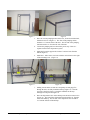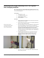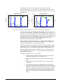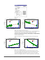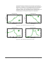
1
Cryo-200
®
VASE Cryostat Attachment
May 10, 1999
By J.A. Woollam Co., Inc.
The CRYO-200 option adapts a Janis Research model ST-400 SuperTran UHV cryostat to a GB-700 VASE ellipsometer
base. This allows the user to control the sample temperature over an extremely wide range, from 4.2 Kelvin to 700
Kelvin, while making transmission measurements or VASE measurements. The windows on the cryostat have a limited
acceptance angle, which in turn limits the VASE measurement angle of incidence to a range of 65° to 75°.
For a complete understanding of the functionality and operation of the cryostat and its support systems it is necessary for
the user to read and understand all the manuals provided by Janis Research. This application note is a VASE operation
supplement and is not a substitute for the training and experience needed for the correct and safe operation of a cryostat.
PLEASE READ AND UNDERSTAND THE MANUALS!
Cryostat nomenclature can be found in the “Introduction to Laboratory Cryogenics” manual provided by Janis Research.
Schematic diagrams located at the back of the “Operating Instructions for the Janis Research Supertran System” are also
useful.
This application note assumes the reader (user) understands the operation of the VASE instrument (See VASE Hardware
Manual and WVASE32 Software Manual).
This manual was produced using Doc-To-Help®, by WexTech Systems, Inc.
Contents
Section 1 Safety Concerns
3
User Safety .......................................................................................................................... 3
Equipment Safety................................................................................................................. 3
Section 2 System Setup
5
Turbo Pump Setup................................................................................................................ 5
Work Table Setup ................................................................................................................ 8
Turbo Pump Operation And Seal Checkout......................................................................... 15
Exchanging Cryostat And Standard Sample Stage............................................................... 17
Cryostat To Sample Stage Exchange ..................................................................... 17
Sample Stage to Cryostat Exchange ...................................................................... 19
Section 3 Configuring WVASE32® For Cryo-200 Attachment
23
Window Strain Effects And Window Calibration ................................................................ 23
Hardware.cnf Entries For The Cryo-200 ............................................................................. 25
Section 4 Cryostat System Operation
29
LakeShore® Temperature Controller, Model 330-5X........................................................... 29
TempReader.exe Utility Program........................................................................................ 31
Removing Cold Finger Assembly From The Cryostat And Changing Samples .................... 34
Inserting Cold Finger Assembly Into The Cryostat And Aligning The Sample..................... 37
Cryogen Transfer ............................................................................................................... 41
Section 5 Ellipsometric Acquisition and Analysis
43
VASE-Dynamic Ellipsometric Acquisition ......................................................................... 43
Monitoring Sample Cool Down With Temperature Cycling ................................................ 45
Adsorption-Rate Data Analysis........................................................................................... 47
Low-Temperature Spectroscopic Measurement................................................................... 51
High-Temperature Spectroscopic Measurement .................................................................. 53
Index
Cryo-200, J.A. Woollam Co., Inc.
57
Contents • i
Section 1 Safety Concerns
User Safety
Operators and Observers MUST to be aware of these
safety concerns:
1) The evaporating gas from the cryogen (Helium or Nitrogen) is
an asphyxiant. While it is not toxic, it will displace the oxygen
in the room and will KILL you just the same! The system
MUST be set up to be in a WELL VENTILATED area.
2) Use only INERT cryogens (e.g. Helium or Nitrogen). Do NOT
USE liquid oxygen or hydrogen as the cryogen.
3) The cryogen and anything it has been in contact with is
unimaginably cold and will cause SEVERE frostbite (cold
burns). The primary danger is from items that have been in
contact with the cryogen. They stay cold and must be allowed
to warm up to room temperatures before being handled.
ALWAYS wear long sleeve shirts, full length pants, covered
toe shoes, safety glasses and insulated gloves when handling
cryogen and items that have been in contact with cryogen!
Equipment Safety
Operators NEED to be aware of these operational
concerns:
1) The transfer line MUST be removed from the cryostat for
operation at temperatures above 475 Kelvin. The transfer line
will be damaged if it is overheated.
Cryo-200, J.A. Woollam Co., Inc.
Section 1 Safety Concerns • 3
2) The cryostat vacuum shell MUST be under vacuum and
continuously pumped during cryostat operation. At elevated
temperatures, outgassing will occur and atmospheric
contaminants (oxygen) will corrode the sample mount. At low
temperatures, atmospheric gases will condense (deposit) on the
sample, altering the sample morphology on a continual basis
making meaningful measurements of the sample difficult.
3) When the cryostat is mounted on the ellipsometer, do not move
the system angle of incidence (AOI) beyond the 0° to 90° range,
either manually or automatically. Doing so will result in
damage to the flexible vacuum hose.
4) The cryostat exhaust port tends to build up condensation or
frost at high cryogen flows. This condensation or frost should
be wiped off as quickly at it is formed. Water and electrical
equipment do not mix.
4 • Section 1 Safety Concerns
Cryo-200, J.A. Woollam Co., Inc.
Section 2 System Setup
Turbo Pump Setup
Any foreign matter inside the
vacuum system will likely
result in major damage to the
pump!
Note: Cleanliness is absolutely essential in this procedure! Any foreign matter
inside the vacuum system will likely result in major damage to the pump! Please
read the instruction manuals for the Edwards Active Gauge Controller and the
Edwards Turbomolucular pump and controller before performing this procedure. A
schematic diagram located at the back of the “Operating Instructions for the Janis
Research Supertran System” contains a general vacuum pump layout and useful
nomenclature.
Figure 1
Tools Needed:
• Clean room gloves
• 1/2” combination wrench, 2 each
Cryo-200, J.A. Woollam Co., Inc.
Section 2 System Setup • 5
Parts Needed:
• Pumping Station, 1 each
• Pump Oil, ½ liter
• 2.51” ID copper gasket, 1 each
• Vacuum tee with gauge and valve, 1 each
• 5/16-24 bolts with nuts and washers, 8 each
Assembly Steps:
1.
Fill the roughing pump with pump oil (Figure 2) as per specification in
the pump manual. (Remove the caution notice when finished.)
2.
Install a new 2.51” ID copper gasket in the seal flange at the top of the
turbomolecular pump (Figure 3).
Figure 2
Figure 3
Incrementally tighten bolts in
cross-cross pattern to avoid
leaks.
6 • Section 2 System Setup
Figure 4
3.
Place the vacuum tee on the seal flange at the top of the turbomolecular
pump with the gauge and valve facing away from the roughing pump.
4.
Install the eight 5/16-24 bolts, washers, and nuts finger tight, making
sure the seal flanges are parallel.
5.
Using the two ½” combination wrenches F( igure 4), gradually tighten
the bolts to 15 lb-ft in ¼ to ½ turn increments using an alternating
criss-cross star pattern (the seal flanges should remain parallel
throughout the entire bolt tightening sequence).
Cryo-200, J.A. Woollam Co., Inc.
6.
Connect Active Gauge Controller cable labeled “Pump Vacuum” to the
gauge on the vacuum tee (Figure 5). The other will be used later on the
cryostat gauge.
7.
The system is now ready to test the integrity of the copper gasket seal
just installed. (If the seal needs to be replaced, it is much more
convenient to fix it before the full work table is assembled.)
8.
Start this check by making sure the main vacuum valve is completely
closed.
9.
Connect the pumping station Isobar (power strip) to AC power.
Figure 5
10. Make sure the power switch for each of the pumping station
components is in the ‘on’ position (turbomolecular pump controller,
active gauge controller, and roughing pump) as well as the main power
switch (all switches are located on the back side of the pumping
station).
11. The pumping station should be powered and the displays active.
Toggle the vacuum gauge display to read the pump vacuum (see the
Edwards Active Gauge Controller manual).
12. Start the vacuum pump by pressing the ‘Start’ button. The pressure
should quickly drop to below 10-4 Torr. If not, there is probably a leak
in the seal between the turbomolecular pump and the vacuum tee. If
there is a leak, try tightening the clamping bolts. If the leak persists,
press the ‘Stop-Start’ button to stop the pump, and let the system return
to atmospheric pressure. Replace the copper gasket seal and try
pumping down again.
13. After the pressure reaches 10-5 Torr, press the ‘Stop-Start’ button to
stop the pump, and let the system return to atmospheric pressure.
The pumping station is now ready for installation in the system.
For additional information on the pumping station components, refer to the
appropriate manual (included with the system). There is no separate manual for the
pumping station as a system.
Cryo-200, J.A. Woollam Co., Inc.
Section 2 System Setup • 7
Work Table Setup
Note: This procedure covers the setup of the CRYO-200 option as it relates to the
ellipsometer and not the setup of the ellipsometer itself. Please read “Operating
Instructions for the Janis Research SuperTran System” from Janis Research.
Schematic diagrams at the end of the Janis manual contain a general cryostat layout
and useful nomenclature. Also read “User’s Manual Model 330 Autotuning
Temperature Controller” from LakeShore. Section 2.6.2.2 contains useful
thermocouple hook up information.
Figure 6
Tools Needed:
• Rubber mallet
• 4mm key wrench
• 7/16” combination wrench
• 9/64” key wrench
• Small straight blade screwdriver
• Small phillips tip screwdriver
Parts Needed (in addition to the ellipsometer):
•
8 • Section 2 System Setup
Table components:
• 8’ side rails, 4 each
• 5’ support rails, 6 each
• 3’ support rails, 6 each
• 3’ support brace, 1 each
• Base, 1 each
Cryo-200, J.A. Woollam Co., Inc.
•
Tabletop, 1 each
•
Cryostat components:
• CRYO-200 storage stand
• CRYO-200 cryostat assembly
• M5 by 16 mm socket head cap screws, 4 each
• 1.45” ID copper gasket, 1 each
• Flexible vacuum line, 1 each
• ¼-28 bolts and nuts, 6 each
• #8-32 Socket head cap screws, 6 each
• #8-32 nut plate, 3 each
• .64” ID copper gasket, 1 each
• Cryogen transfer line, 1 each
• Cryogen dewar (not included)
•
Temperature controller components:
• Temperature controller, 1 each
• Power cord, 1 each
• Cold Junction Compensator, 1 each
• Thermocouple cable, 1 each
• Heater cable, 1 each
•
Exhaust port heater components:
• Heater controller, 1 each
• Power cord, 1 each
• Heater cable, 1 each
• Pumping station components:
• Assembled pumping station, 1 each
• Isobar power strip, 1 each
Facility Needs:
• Well ventilated room
• Computer Stand
• 4’ by 8’ floor space (plus room for computer stand) with 9’ ceiling
• 15 amp 120 VAC outlet (separate circuit from the ellipsometer)
Assembly Steps:
Cryo-200, J.A. Woollam Co., Inc.
1.
Assemble the outer frame (Figure 7 and Figure 8). A rubber mallet will
be necessary to persuade the supports into place. All four base supports
(two 3’, two 5’) should be in the #2 and #3 holes from the bottom.
Three of the top supports (one 3’, two 5’) should be in the #2 and #3
holes from the top. The last top support (3’) should be in the #6 and #7
holes from the top (this acts as a support for the cryogen transfer line
and should be located on the left hand side of the table).
2.
Install the base shelf.
Section 2 System Setup • 9
Figure 7
Figure 8
3.
Place the vacuum pumping station on the base, located toward the back,
left hand corner as in Figure 11. The front of the pumping station
should be 17” from the front of the base. The left side of the pumping
station should be 12” from the left side of the base.
4.
Connect the pumping station to the Isobar power strip. There is a
separate Isobar for the ellipsometer system.
5.
Install the four table support rails in the#17 and #18 holes from the
bottom (Figure 9).
6.
Install the 3’ table-center cross brace with the vertical brace to the right
of the mounting rivets. (Figure 11)
Figure 9
10 • Section 2 System Setup
Figure 10
7.
Making sure the main vacuum valve and pump vacuum gauge fits
through the hole, carefully install the tabletop (Figure 10). Note the
cross brace shown in Figure 11 should be installed for this step
although it not depicted in Figure 10.
8.
Place the ellipsometer base on the tabletop near the main vacuum valve
(Figure 11). The front of the ellipsometer base should be 10” from the
front of the tabletop. The left side of the ellipsometer base should be
16” from the left side of the tabletop.
Cryo-200, J.A. Woollam Co., Inc.
Figure 11
9.
Figure 12
Carefully place the CRYO-200 assembly on the ellipsometer base
(Figure 12), oriented such that the z-axis adjust knob faces toward the
input unit when the AOI is at 0°.
Figure 13
10. Install four M5 socket head cap screws finger tight to mount the
CRYO-200 assembly to the ellipsometer base.
11. Use the 4mm key wrench to tighten the M5 socket head cap screws
(Figure 13).
12. Install a new 1.45” ID copper gasket in the seal flange at the top of the
main vacuum valve (Figure 14).
13. Mate the flexible vacuum hose 2-3/4” seal flange up to the main
vacuum valve seal flange at the top of the vacuum tee.
14. Install the six ¼-28 bolts and nuts finger tight through the seal flanges,
making sure the seal flanges are parallel.
Cryo-200, J.A. Woollam Co., Inc.
Section 2 System Setup • 11
Figure 14
Figure 15
15. Using two 7/16” combination wrenches (Figure 15), gradually tighten
the bolts to 12 lb-ft in ¼ to ½ turn increments using an alternating criss
cross star pattern (the seal flanges should remain parallel throughout
the entire bolt tightening sequence).
16. Install a new .64” ID copper gasket in the seal flange of the cryostat
vacuum valve (Figure 16).
Figure 16
17. Mate the flexible vacuum hose 1-1/3” seal flange to the cryostat
vacuum valve seal flange.
18. Install the six #8-32 screws and three nut plates finger tight through the
seal flanges, making sure the seal flanges are parallel.
19. Make sure the AOI can move the full 0° to 90° range without placing
undo strain on the flexible vacuum hose (refer to VASE Hardware
manual for instructions on manually changing the AOI).
20. Using the 9/64” key wrench (Figure 17), gradually tighten the screws to
7 lb-ft in ¼ to ½ turn increments using an alternating criss
-cross star
pattern (the seal flanges should remain parallel throughout the entire
bolt tightening sequence).
12 • Section 2 System Setup
Cryo-200, J.A. Woollam Co., Inc.
Figure 17
21. Place the exhaust port heater controller on the tabletop next to the main
vacuum valve (Figure 18).
22. Place the temperature controller on the tabletop next to the ellipsometer
base (Figure 18).
Figure 18
23. Connect the exhaust port heater to its controller using the cable
provided (Figure 19 and Figure 20).
Figure 19
Cryo-200, J.A. Woollam Co., Inc.
Figure 20
Section 2 System Setup • 13
24. Connect the exhaust port heater controller to the vacuum pumping
station Isobar using the cord provided.
25. Connect the cryostat thermocouple to the cold junction compensator
using the cable provided (Figure 21 and Figure 22).
Figure 21
Figure 22
26. Using the small phillips tip screwdriver, connect the cold junction
compensator to the temperature controller (Figure 23).
Figure 23
Figure 24
14 • Section 2 System Setup
Figure 25
Cryo-200, J.A. Woollam Co., Inc.
27. Connect the sample heater to the temperature controller with the cable
provided (Figure 24 and Figure 25).
28. Connect the temperature controller to the vacuum pumping station
Isobar using the cord provided.
29. Connect Active Gauge Controller cable labeled “Cryostat Vacuum” to
the gauge on the cryostat vacuum chamber (Figure 26).
Figure 26
This completes the installation of the CRYO-200 option on the ellipsometer base.
The ellipsometer installation may now be completed.
The cryostat was shipped with a thermal oxide (~250Å) on silicon sample mounted
on the cold finger. Ellipsometer and data acquisition test can be performed.
Turbo Pump Operation And Seal Checkout
Some general trouble-shooting and operational comments are presented below.
UHV systems have a complex nature which is beyond the scope of this manual. For
an in depth understanding of UHV, consult relevant books, journals, and experienced
colleagues.
•
Cryo-200, J.A. Woollam Co., Inc.
Leaks have a large number of causes. The most obvious are:
•
‘Recycling’ used copper gaskets. You might get lucky and get one to
seal, but how much time do you want to spend fixing a known source
of trouble? Always use fresh copper gaskets when assembling a UHV
seal.
•
Improper torque sequence. Torquing of the seal bolts in an uneven
manner will cause uneven compression of the gasket causing it to leak.
Loosen and re-torque seal bolts in the prescribed fashion. If the
torquing is really bad, the gasket will have to be replaced.
•
Inadequate torque. Seals rely on bolt tension to compress the gasket
and hold it in intimate contact with the seal surface. Torque the seal
bolts to the prescribed value.
•
Dirt on seal mating surfaces. Dirt keeps the gasket from coming into
intimate contact with the seal surfaces and may damage the seal
surfaces. Always check your seal surfaces for foreign material (dirt,
lint, dust, hair, etc.) before assemble a UHV seal. Replace the gasket
and clean the seal surfaces.
Section 2 System Setup • 15
It is recommended to keep the
vacuum line and cryostat
shell under vacuum to prevent
water adsorption.
•
During pumpdown, there can easily be two (or more) orders of magnitude
difference in the pressure between the pump and cryostat chamber. Even after
pumpdown, there can be an order of magnitude difference.
•
If the system is well sealed, water vapor will be the major contaminant in the
chamber and it can take weeks to pump out. Therefore it is recommended to
keep the flexible vacuum line and the cryostat shell under vacuum to prevent
water adsorption. For extended idle times, the valves can be closed and the
turbo pump turned off.
•
The start/stop cycle of the pumping station is an automated sequence, and may
not immediately appear to be functioning.
The following procedures will check the integrity of the three copper gasket seals
just installed. The seal just above the turbo pump should have already been checked
before assembling the table, but check it again at this time.
Check seal between pump
and vacuum tee.
Check seals at ends of the
vacuum transfer line.
16 • Section 2 System Setup
1.
Make sure the main vacuum valve and the cryostat vacuum valve are
completely closed.
2.
Connect the pumping station Isobar to AC power (separate circuit from
the ellipsometer).
3.
Make sure the power switch for each of the pumping station
components is in the ‘on’ position (turbomolecular pump controller,
active gauge controller, and roughing pump) as well as the main power
switch (all switches are located on the back side of the pumping
station).
4.
The pumping station should be powered and the displays active.
Toggle the vacuum gauge display to read the pump vacuum (see the
Edwards Active Gauge Controller manual).
5.
Start the vacuum pump by pressing the ‘Start’ button. The pressure
should quickly drop to below 10-4 Torr. If not, there is probably a leak
in the seal between the turbomolecular pump and the vacuum tee. If
there is a leak, try tightening th clamping bolts. If the leak persists,
press the ‘Stop-Start’ button to stop the pump, and let the system return
to atmospheric pressure. Replace the copper gasket seal and try
pumping down again.
6.
While monitoring the pump vacuum gauge, very slowly open the main
vacuum valve such that the pump gauge pressure never exceeds 1 Torr.
Once the valve is fully open, the pressure should quickly drop to below
10-4 Torr. If not, there is probably a leak in one of the seals at the ends
of the flexible vacuum hose. If there is a leak, try tightening clamping
bolts. If the leak persists, close the main vacuum valve, but the turbo
pump can be left running. Replace the copper gasket seal(s) and try
pumping down again.
7.
Wait for the pump gauge pressure to reach 10-5 Torr.
Cryo-200, J.A. Woollam Co., Inc.
Check cryostat seals.
8.
While monitoring the pump vacuum gauge, very slowly open the
cryostat vacuum valve such that the pump gauge pressure never
exceeds 1 Torr. The cryostat was shipped under vacuum so the
pressure should not rise appreciably, but go slowly for safety. Once the
valve is fully open, the pressure should quickly drop to below 10-4
Torr. If not, there is probably a leak in one of the seals on the cryostat.
If there is a leak, try tightening the clamping bolts. You may want to
close the cryostat vacuum valve and confirm that problem is really with
the cryostat itself. If the leak persists, start the seal chck out procedure
again to isolate which seals could possible be at fault. Replace the
copper gasket seal(s) and try pumping down again.
Exchanging Cryostat And Standard Sample Stage
Cryostat To Sample Stage Exchange
Tools Needed:
• 4mm key wrench
• 3/16” key wrench
Parts Needed:
• Sample stage components:
• Sample chuck assembly, 1 each
• Z-axis stage, 1 each
• ¼-20 by 3/8” socket head cap screws, 6 each
Procedures:
The copper radiation shield
does not warm up or cool
down as fast as the cold
finger.
Cryo-200, J.A. Woollam Co., Inc.
1.
The cryostat storage pedestal should be positioned behind the
ellipsometer, straddling the ellipsometer base connecting cables.
2.
Set the system angle of incidence to 0° (via the Move Angle
command).
3.
Allow the cold finger to come to room temperature. If the cryostat has
been cold, the temperature controller may be set to 295 Kelvin to
quickly warm up the sample. If the cryostat has been hot, cryogen may
be used to cool the sample.
4.
Completely unscrew the transfer line O-ring compression nut and
carefully withdraw the transfer line bayonet from the cryostat by
pulling the transfer line straight up (Figure 27 and Figure 28). A step
stool may be necessary to accomplish this step. Caution: The bayonet
may be cold! Observe proper safety precautions!
Section 2 System Setup • 17
Figure 27
5.
Figure 28
Using the 4mm key wrench, remove the four M5 socket head cap
screws that hold the cryostat assembly to the goniometer base (Figure
29). These screws will be used to fasten the cryostat assembly to its
storage stand.
Figure 29
Be Careful! The cryostat and
tilt stage are heavy.
6.
Figure 30
18 • Section 2 System Setup
Using care not to strain the flexible vacuum hose (if attached to the
cryostat chamber), gently move the cryostat assembly to its storage
stand (Figure 30).
Figure 31
Cryo-200, J.A. Woollam Co., Inc.
7.
Install the four M5 socket head cap screws finger tight through the
CRYO-200 base into the storage stand.
8.
Using the 4mm key wrench, tighten the four M5 socket head cap
screws (Figure 31).
9.
Using the 3/16” key wrench, bolt the sample z-axis stage to the
goniometer base with two ¼-20 socket head cap screws (Figure 32).
Figure 32
10. Using the 3/16” key wrench, bolt the Sample Chuck on the sample zaxis stage with four ¼-20 socket had cap screws (Figure 33).
Figure 33
Figure 34
11. Attach the sample vacuum to the sample chuck (Figure 34).
Make sure goniometer dials
agree with the WVASE32
settings.
12. Check the angles in the Motor Settings and make sure they agree with
the goniometer positions. Zero the fine scales on the goniometers if
necessary (See VASE Hardware Manual).
Sample Stage to Cryostat Exchange
Tools Needed:
• 3/16” key wrench
• 4mm key wrench
Procedures:
Cryo-200, J.A. Woollam Co., Inc.
Section 2 System Setup • 19
1.
Set the system angle of incidence to 0° (via the Move Angle
command).
2.
Disconnect the vacuum from the sample chuck (Figure 35). Connect
the vacuum hose to the dummy connection on the sample goniometer.
Figure 35
3.
Remove the four ¼-20 socket head cap screws that hold the sample
chuck to the sample Z-Axis stage (Figure 36).
4.
Remove the two ¼-20 socket head cap screws holding the sample zaxis stage to the sample goniometer (Figure 37).
Figure 37
20 • Section 2 System Setup
Figure 36
Figure 38
5.
Store the removed Sample Stage components for reuse (Figure 38).
6.
Using the 4mm key wrench, remove the four M5 socket head cap
screws holding the cryostat assembly to its storage stand (Figure 39).
These bolts will be used to fasten the cryostat assembly to the
goniometer base.
Cryo-200, J.A. Woollam Co., Inc.
Figure 39
Be Careful! The cryostat and
tilt stage are heavy.
1.
Figure 40
Using care not to strain the flexible vacuum hose (if attached to the
cryostat chamber), gently move the cryostat assembly to the
goniometer base with the Z Axis micrometer knob on the input unit
side (Figure 40).
Figure 41
7.
Install the four M5 socket head cap screws finger tight through the
CRYO-200 base into the ellipsometer base.
8.
Using the 4mm key wrench, tighten the four M5 screws (Figure 41).
Note: Keeping the cryostat vacuum chamber under vacuum during storage is
highly recommended. This removes the possibility of chamber contamination,
minimizing the pump-down time required before usage.
Cryo-200, J.A. Woollam Co., Inc.
Section 2 System Setup • 21
This page left blank intentionally.
22 • Section 2 System Setup
Cryo-200, J.A. Woollam Co., Inc.
Section 3 Configuring
®
WVASE32 For Cryo-200
Attachment
Window Strain Effects And Window Calibration
Obviously windows are needed on a vacuum chamber to permit an optical probe to
reach the sample without letting the vacuum “leak out”. However, with windows
comes the possibility of strain effects which can perturb the polarization state of the
probe beam. These effects and the general WVASE32® scheme for handling them
are discussed below.
The Cryo-200 comes with standard, fused-silica, UHV windows, and these windows
generally have some strain. Expensive, fragile “strain-free” windows, which might
be more appropriately named “lower-strain-when-shipped”, have been developed.
Regardless of the window type, if there is detectable window strain (the usual
situation) then that strain needs to be accounted for, not ignored, and the accuracy of
the strain model will be about the same whether a small or moderately-large strain
effect is present.
In general terms, the effect of window strain can be divided into two parts. Part 1 is
a pure window effects which can be determined when the ellipsometer is calibrated
for a very wide range of samples. Part 2 is a window effect which merges
completely with the measured ∆ value for the sample. Part 1 effects are referred to
as WinEffects, and Part 2 effects are referred to as DelOffsets. (See hardware.cnf
section below.)
Cryo-200, J.A. Woollam Co., Inc.
Section 3 Configuring WVASE32® For Cryo-200 Attachment • 23
With windows, the measured
ψ and ∆ values must be
interpreted as applying to the
window-sample-window
system as a whole.
Data files are tagged with the
appropriate window effects
information for use when
analyzing the data.
To analyze multiple-angle
cryostat data, use multiple
models, with data at one
angle per model.
For normal operation, it is
not necessary to recalibrate
window effects. Previously
stored values will be used.
One tractable, but unfortunate, consequence of windows combined with a rotatinganalyzer ellipsometer is that the window effects can not be fully disentangled from
the measured ψ and ∆ values at acquisition time. Without windows, a rotatinganalyzer system has an ambiguity with respect to sign of ∆ which is not a serious
problem because ∆ can be mapped back to the 0-180° range for analysis. However,
with windows present, the measured ∆ relates to the combined window-samplewindow system and there is no general, convenient mapping to apply. With
windows, the measured ψ and ∆ values are not intrinsic sample parameters. The
measured ψ and ∆ values must be interpreted as applying to the complete windowsample-window system. WVASE32® manages this complication by tagging the data
files with the appropriate window effects information which is automatically loaded
into the Model Options when the data file is loaded.
The spread of strain effects across the window also needs to be considered if data is
to be taken at more than one angle. As discussed in the next section, the Cryo-200
attachment has its windows divided (via software) into different zones for different
angle of incidence ranges. As data is acquired at different angles, window effects for
that angle zone are tagged with the data file. However, for analysis, any single
model and corresponding experimental data can have only one set of window
effects. Therefore, one can not simultaneously model cryostat data acquire at
different angles of incidence using a single model. To analyze multiple-angle
cryostat data, use multiple models, with data at one angle per model.
The Part1, WinEffects, values can in principle be determined with each normal
hardware calibration. However, the default operating procedure for the Cryo-200 is
to not fit new window effects. With the Cryo-200 present the following additional
dialog box is displayed during the normal calibration procedure. For normal
operation, the recommend action is to select ‘No’ at this stage.
Figure 42
A WinEffects system
calibration requires a
thermal-oxide calibration
sample.
If the WinEffects are to be recalibrated, then it is recommended that a full window
system calibration be performed. A window system calibration determines
appropriate WinEffects and DelOffsets. A system calibration entails loading a piece
of the thermal-oxide calibration wafer (provided with the system) as the cryostat
sample and then running a special script file. Because the system calibration is a
combined spectroscopic calibration and model fit, the sample need only have an
oxide thickness near the nominal 250Å. (Other simple samples, which can be fit to
high accuracy without windows present, could also be used.) The data acquisition
and analysis takes about two hours. If the windows are removed or substantial
external heat is applied to bake out the chamber, the windows will need to be
recalibrated. Otherwise, the windows are typically stable.
Procedures:
1.
The CRYO-200 was shipped with the correct calibration sample inside.
If it is still present you can skip the steps relating to installation of a
new sample.
24 • Section 3 Configuring WVASE32® For Cryo-200 Attachment
Cryo-200, J.A. Woollam Co., Inc.
2.
Remove the cold finger assembly referring to procedures described in
the section on “Removing Cold Finger Assembly From The Cryostat
And Changing Samples.”
3.
Place the calibration sample on the cold finger.
4.
This calibration should be performed near room temperature (~297K)
and does not require a vacuum. If this sample is only going to be used
to calibrate the windows, then it is probably unnecessary to replace the
copper gasket when returning the cold-finger assembly to the cryostat.
(If the system is going to be pumped down, then replace the seal.)
5.
Perform a proper coarse alignment as described in the section on
“Inserting Cold Finger Assembly In To The Cryostat And Aligning The
Sample.”
6.
The seal clamping bolts should be tightened enough to prevent the
sample from moving around. Then a fine alignment should be
performed.
7.
Perform a fine calibration at 70° and select fitting for window effects
when that dialog appears. (Figure 44) If the calibration is successful,
continue with the system calibration. If the fine calibration was
unsuccessful, you may need to perform a coarse calibration. It is
important to confirm that the system is capable of being calibrated
before starting the multiple system calibrations that follow.
8.
Launch the WSCRIPT.exe script running application using the
|Global|Run_WVASE_Tools menu. See Figure 43.
9.
Load the ‘ftdelwin.wsc’ script file. See Figure 44 below.
10. Run the script. This should take about two hours.
11. The first time this procedure is completed without a J.A. Woollam Co.
representative in attendance, the user should e-mail the company the
“\wvase32\current.log” file for validation of the procedure.
Figure 43
Figure 44
Hardware.cnf Entries For The Cryo-200
The hardware.cnf file contains the hardware configuration information that tells
WVASE32® what kind of ellipsometer system is available and how to control that
system. Configuration entries specific to the Cryo-200 are described below.
Cryo-200, J.A. Woollam Co., Inc.
Section 3 Configuring WVASE32® For Cryo-200 Attachment • 25
In the [Hardware] section of the hardware.cnf file, the following entry identifies
‘attachment1’ as ‘cryostat’. In turn this causes WVASE32® to look for the [cryostat]
subsection for more configuration entries.
[Hardware]
attachment1=1 cryostat
The following lines provide acquisition guidelines for WVASE32® to use when the
presence of the Cryo-200 is detected.
[Cryostat]
switchconfig=27 1
AllowAlignJogs=1
fixedpolalways=1 20
;zoneavealways=1
The ‘switchconfig’ entry tells the program that when sensor bit #27 is active, the
Cryo-200 is present. There is a proximity switch in the sample stage base that
detects the presence of the cryostat. The ‘AllowAlignJogs’ entry enables the
left/right arrow keys to be used for left/right, fine sample alignment, but only with
the Cryo-200 present. The ‘fixedpolalways’ entry tells the program that the polarizer
must be fixed for a given scan (needed because of possible window effects), and that
the fixed polarizer azimuth must be 20° (or ±20° if zone averaged). The
‘zoneavealways’ entry, which is commented out (not active) in the above example,
would force zone averaged data acquisition. While this is not an absolute
requirement, zone averaging the polarizer is highly recommended, even without
possible window strain.
The Cryo-200 should be used
at integer angles of incidence
and is principally designed to
work at 70°
The remaining [Cryostat] entries define the angle zones for the windows, define how
window effects will be calibrated, and specify the current window effects are. As
shipped, the ellipsometry windows were divided into 14 zones, most of which are 1°
wide and centered on an integer angle. These values should not be directly modified
by the user. Any changes in the current window effect values. will be entered by
WVASE329® as the results of a calibration.
[Cryostat]
nZones=14
angzone=70 69.5 70.5
angzone2=0 -10 10
angzone3=71 70.5 71.5
angzone4=72 71.5 72.5
angzone5=73 72.5 73.5
angzone6=74 73.5 74.5
angzone7=75 74.5 75.5
angzone8=76 75.5 80
angzone9=69 68.5 69.5
angzone10=68 67.5 68.5
angzone11=67 66.5 67.5
angzone12=66 65.5 66.5
angzone13=65 64.5 65.5
angzone14=64 50 64.5
wineffects=2 -1.34693 -1.50901 0.00178 0.00056
winfitmode=2
26 • Section 3 Configuring WVASE32® For Cryo-200 Attachment
Cryo-200, J.A. Woollam Co., Inc.
wineffects2=2 0.00000 1.21400 0.05869 -0.00282
winfitmode2=12
wineffects3=2 -1.29704 -1.39076 0.00583 0.00047
wineffects4=2 -1.16826 -1.25907 0.00278 0.00054
wineffects5=2 -0.85683 -1.04749 -0.00052 0.00069
wineffects6=2 -0.80369 -0.71778 -0.00645 0.00119
wineffects7=2 -0.27786 -0.28113 -0.03636 0.00242
wineffects8=2 0.08332 0.26995 -0.04420 0.00278
wineffects9=2 -1.55471 -1.52092 0.00240 0.00055
wineffects10=2 -1.66636 -1.50378 0.00036 0.00069
wineffects11=2 -1.39243 -1.37807 -0.00363 0.00077
wineffects12=2 -1.30172 -1.21444 -0.00380 0.00066
wineffects13=2 -1.26951 -0.88734 -0.00646 0.00070
wineffects14=2 -1.43652 -0.40560 -0.00191 0.00041
DelOffsets=2 0.45295 0.00178 0.00056 0.500
DelOffsets=2 0 0 0 .5
deloffsets2=2 0 0 0
deloffsets3=2 -0.08044 0.00583 0.00047 0.500
deloffsets4=2 -0.70477 0.00278 0.00054 0.500
deloffsets5=2 -1.27227 -0.00052 0.00069 0.500
deloffsets6=2 -1.58812 -0.00645 0.00119 0.500
deloffsets7=2 -2.30921 -0.03636 0.00242 0.500
deloffsets8=2 -2.85260 -0.04420 0.00278 0.500
deloffsets9=2 1.05519 0.00240 0.00055 0.500
deloffsets10=2 1.80334 0.00036 0.00069 0.500
deloffsets11=2 2.58509 -0.00363 0.00077 0.500
deloffsets12=2 3.45108 -0.00380 0.00066 0.500
deloffsets13=2 4.23914 -0.00646 0.00070 0.500
deloffsets14=2 5.16073 -0.00191 0.00041 0.500
The ‘User1’ value is the
temperature passed to
WVASE32® by
TempReader.exe
The [User] subsection tells the program to look for an external ‘User1’ value to be
used when acquiring dynamic data. For the Cryo-200, the ‘User1’ value is the
temperature passed to WVASE32® by the TempReader.exe utility program.
[User]
User1=1 0
User1Cal=0
Cryo-200, J.A. Woollam Co., Inc.
Section 3 Configuring WVASE32® For Cryo-200 Attachment • 27
This page left blank intentionally.
28 • Section 3 Configuring WVASE32® For Cryo-200 Attachment
Cryo-200, J.A. Woollam Co., Inc.
Section 4 Cryostat System
Operation
LakeShore® Temperature Controller, Model 330-5X
The LakeShore manual is
the primary reference for the
temperature controller.
The extended Type-E
thermocouple used from 4700K is not standard. See the
LakeShore manual addendum
and the TempReader.exe
description.
Cryo-200, J.A. Woollam Co., Inc.
The primary documentation for the LakeShore® Model 330-5X Temperature
Controller is the LakeShore manual shipped with the system. Only some of the
important features and operational considerations are discussed here.
The Cryo-200 is equipped with an extended Type-E thermocouple to monitor
temperatures from 4 to 700K. The LakeShore controller does not have a calibration
curve for this extended range thermocouple stored in permanent memory (curves 110, See LakeShore page 2-8). The controller is shipped with extended Type-E
calibration values stored Curve #12 in non-volatile RAM. The curve will remain
stored in memory during normal operations including turning the power off, but the
curve can be deleted by resetting to factory defaults (See LakeShore page 3-13). If
the curve becomes lost or corrupted, a new curve must be downloaded before correct
temperature measurements are possible. There is a special format for downloading
an extended Type-E calibration which is found in the one page addendum to
LakeShore manual. The TempReader.exe utility program can be used to download
new calibration curves as discussed in the next section.
Section 4 Cryostat System Operation • 29
It the temperature controller
oscillates badly, examine the
“P” (proportional) control
parameter. It may need to be
manually adjusted.
On the Cryo-200, the LakeShore controller regulates temperature solely by adjusting
power delivered to a resistive heater embedded in the cold finger. Thus, to maintain
temperature control, heat dissipation either by evaporating cryogen (below room
temperature) or by conductive/convective losses (above room temperature) is
required to pull against the heater. Because the pull-down heat dissipating forces in
the system (e.g. cryogen flow rate) tend to be highly variable, it is difficult to
determine universally optimal PID control parameters. The LakeShore controller is
capable of sophisticated multi-zone temperature PID control functions which are
outside the coverage of this manual, however, the user is encouraged to try using the
AutoTune feature of the controller for most control applications. Occasionally the
AutoTune feature will drive one of the PID control parameters too far in one
direction requiring the user to make a manual adjustment (see LakeShore page 3-10).
For instance, if temperature control oscillates very badly, the P (proportional) value
may be too large, e.g. 650, and needs to be reset to a more stable value like 20.
There are several factors which may affect accuracy and precision of the monitored
thermocouple temperature. The users should be aware of these potential limitation
and should gauge their importance relative to the particular experiment under
consideration.
1) Thermocouple voltage measurements may have some offset induced by
undesired junctions in the wiring. These are effects are reduced by the cold
junction compensating device in-line with the thermocouple. Additional offset
correction capability is available using the TempReader.exe utility to down load
a modified calibration curve to exactly match one or two known temperatures to
a measured voltage.
2) The extended Type-E thermocouple which covers a very wide temperature
range, is much less sensitive to temperature changes around 4K than it is around
300K.
3) The sample temperature may not be exactly the same as the thermocouple. The
thermocouple is in close proximity with the heater and helium outlet in the coldfinger assembly. The thermocouple needs to be close to the hot/cold source for
control stability (see “Introduction to Laboratory Cryogenics” page 65).
However, this permits a temperature offset to exist between the sample and the
thermocouple. Furthermore, the offset between sample and thermocouple may
depend not only on what the control temperature is, but also on how much
cooling/heating is taking place to maintain that control temperature. An
experiment using a secondary temperature probe may be possible to characterize
the sample-thermocouple offset as a function of control temperature and
controlling heater power.
4) There is a time lag between the sample temperature and the thermocouple
monitor temperature for the same reasons discussed in point 3 above.
30 • Section 4 Cryostat System Operation
Cryo-200, J.A. Woollam Co., Inc.
TempReader.exe Utility Program
Make sure the LakeShore
baud rate is set to 1200. See
LakeShore page 3-13.
The TempReader utility written by J.A. Woollam Co., is a simple program that
performs just the three basic tasks as described below. It is not a general control
program for the LakeShore. If a more sophisticated WVASE32®-LakeShore®
interfacing program is required for a particular experiment, the user will need to
contact the J.A. Woollam Co., for more information on the WVASE32® external
programming interface (EPI). A screen shot of the inactive TempReader window is
shown below. TempReader can be started from the Global|Run_WVASE_Tools
menu from inside WVASE32®, or it can be launched directly from the operating
system out of the \wvase32\tools subdirectory. TempReader assumes a baud rate of
1200 bit/s using the computer’s ComPort #1. If these values need to be changed,
contact J.A. Woollam Co. for more information.
Figure 45 TempReader.exe front screen.
Cryo-200, J.A. Woollam Co., Inc.
Section 4 Cryostat System Operation • 31
1) TempReader can poll the
current sensor temperature
and pass that value along to
WVASE32®.
The utility can be used to poll the current sensor temperature from the controller
using a serial communications port, and then advise WVASE32® what the current
temperature is. WVASE32® can then store the current temperature (USER1 value)
with the measured ellipsometric data. (See Acquisition and Analysis Section) The
polling controls are in the upper left hand corner. The update period can be selected
between 0.5 and 60 seconds. The same button is used to Start Polling and Stop
Polling. The Close Comm Port button may help clear the program if the program
gets caught in a series of repeated errors. Error information is presented in the text
box on the right side. Serial communications under Windows® tends to produce
some errors. As a general matter, TempReader deals with these errors by ignoring
them and then restarting the polling process. The goal is to send only correct
temperatures to WVASE32®, thus not all polling attempts are successful.
2) TempReader can
download a thermocouple
calibration curve and apply
an optional user-defined
correction.
TempReader can also download a thermocouple calibration curve. By default,
TempReader works with a file called “type-e_extended.cnf” and curve #12. The
currently configured curve# and file are displayed in the TempReader text box when
the application is launched. (See Figure 45.) The default curve# and filename can
be changed by using command-line arguments which are accessible using a
Windows® shortcut to launch TempReader. For example, if the command line
contains “curve#=13, curve=type-e_alternate.cnf”, then TempReader will look for a
file called “type-e_alternate.cnf” and download the values to curve #13 if directed to
do so. The format for a thermocouple “.cnf” file can be seen the in the text of “type-e_extended.cnf” at the end of this section.
A linear, user-specified correction can be applied to the calibration curve before
downloading using the ‘Real Temp’ and ‘Meas’ text boxes in the lower left corner.
By using known cryogenic control temperatures, such as imersion in liq. helium or
liq. nitrogren, the actual measured thermocouple voltage can be measured by
selecting the mV units display. (See LakeShore 3-3) A measurement with the cold
finger assembly outside the cryostat and at equilibrium at room temperature can
provide another known temperature, assuming a secondary accurate temperature
measurement is available. It is not recommended to directly immerse the cold finger
in ice water because water vapor is primary background gas at the vacuum pressures
typical for the cryostat. In all cases, remember that even if the thermocouple were
perfectly calibrated, the temperature of interest is the temperature of the sample.
(See end of previous LakeShore® Temperature Controller section.)
In Figure 45, the ‘Meas’ boxes contain -999 which cause NO correction to be
applied. If exactly one of the ‘Meas’ boxes contains a value which is not -999, then
TempReader will adjust the downloaded calibration voltages by a constant offset to
match the actual measured value for the specified temperature. Of course the
preferred method is to make the measured voltage match the thermocouple values
using proper wiring techniques and the ice-point buffer module. If both ‘Meas’
boxes contain values which are not -999, then a linear correction to the downloaded
voltages is made such that the measured values match both specified temperatures.
A two-point correction effectively shifts and tilts the calibration curve to match the
known measured points.
32 • Section 4 Cryostat System Operation
Cryo-200, J.A. Woollam Co., Inc.
TempReader does NOT
perform a plausibility check
on the user defined
correction.
Note, TempReader does not perform a plausibility check on the user defined
correction. Therefore, very inaccurate temperature read outs can occur. A potential
hazard exists if the LakeShore is instructed to control the temperature with an invalid
calibration curve. For example, the heater might turn on and remain at full power
indefinitely because the desired temperature can never be reached. (The same thing
would also happen if an unreachable temperature was selected as the control point,
even with accurate calibration values.)
3) TempReader can pass
commands to the controller
to test the serial link and to
examine the controller
NOVRAM.
TempReader can also pass single commands to the LakeShore and read the returned
string. The Manual Send String button sends the text from the box above the button
and waits for a return if the string contained a ‘?’ characters. (See LakeShore 4-8 to
4-22 for a complete description of commands). Do not send commands to the
LakeShore while polling is active.
The primary purpose of this feature is to test the serial link to the controller. The
sensor units query command ‘suni?’ shown in Figure 45 will return a ‘K’, ‘C’, or
‘mV’ depending on the display of the controller. If this command succeeds, one is
assured that serial communication has been established.
There are a variety of commands used to control and query the LakeShore controller.
Tests with this feature may be a useful way for the user to develop a separate, more
sophisticated control package. Also, some of the NOVRAM values are more easily
interrogated using the serial link. Text can be clipped from the log box and pasted
into different applications for printing.
File “type-e_extended.cnf” contains the following text. The tabulated values are
measured voltage in mV and corresponding temperature in degrees Kelvin. Please
note, that for an extended-type thermocouple, both columns of numbers are modified
before downloading to the LakeShore controller. See the LakeShore Model 330-5X
Addendum for more information.
S99EXTENDED TYPE E
P
-15
0
-9.835
3
-9.831
5
-9.821
8
-9.813
10
-9.797
13
-9.777
16
-9.746
20
-9.642
30
-9.503
40
-9.332
50
-9.129
60
-8.899
70
-8.642
80
-8.362
90
Cryo-200, J.A. Woollam Co., Inc.
-7.733
-7.02
-6.231
-4.916
-3.459
-1.874
-0.176
1.617
4.786
8.168
11.73
15.435
21.189
27.106
33.122
39.184
43.228
110
130
150
180
210
240
270
300
350
400
450
500
575
650
725
800
850
Section 4 Cryostat System Operation • 33
Removing Cold Finger Assembly From The Cryostat
And Changing Samples
Note: Wear insulated gloves while handling cold or potentially cold items. Wear
latex or suitable clean room type gloves while handling parts internal to the cryostat
to avoid contaminating them.
Tools Needed:
• Insulated Gloves, 1 pair
• ½” combination wrench, 1 each
• Clean room gloves, 1 pair
• Small straight blade screwdriver
• 3/32” key wrench
Procedures:
Do not vent the cryostat
vacuum shell until the sample
and raditation shield have
come to room temperature!
1.
Set the ellipsometer to the alignment mode and follow the instruction
prompts given by the computer.
2.
Jog the sample stage angle (fine scale) to zero using the right and left
arrow keys on the computer keyboard.
3.
Allow the cold finger to come to room temperature. If the cryostat has
been cold, the temperature controller may be set to 295 Kelvin to
quickly warm up the sample. If the cryostat has been hot, cryogen may
be used to cool the sample. Note: Do not vent the cryostat vacuum
shell until the sample and raditation shield have come to room
temperature! Parts at elevated temperatures will corrode (permanent)
or at reduced temperatures will frost instantly (water contamination is
time consuming to remove).
4.
Completely unscrew the transfer line o-ring compression nut and
carefully withdraw the transfer line bayonet from the cryostat by
pulling the transfer line straight up (Figure 47 and Figure 47).
Caution: the bayonet may still be cold! Observe proper safety
precautions.
Figure 46
5.
34 • Section 4 Cryostat System Operation
Figure 47
Disconnect the cables from the sample heater, sample thermocouple,
and the exhaust port heater.
Cryo-200, J.A. Woollam Co., Inc.
6.
Note: In order to reduce vacuum chamber contamination (which will
significantly increase the pump down time), minimize the time the
vacuum chamber is exposed to the atmosphere. Be organized, work
quickly, do not leave the system lay open unnecessarily.
7.
Close the cryostat vacuum chamber valve (Figure 48).
8.
Using the ½” combination wrench, remove the eight 5/16-24 cap head
bolts that seal the cryostat vacuum chamber (Figure 49).
Figure 48
9.
Figure 49
Withdraw the cryostat by lifting it straight up out of the vacuum jacket
(Figure 50). Caution: The radiation shield may still be cold (or hot).
Observe proper safety precautions.
Figure 50
10. Lay the cryostat in its cradle with the sample facing up (Figure 51).
Cryo-200, J.A. Woollam Co., Inc.
Section 4 Cryostat System Operation • 35
Figure 51
11. Allow the radiation shield to come to room temperature.
12. Using a small straight blade screwdriver, remove the four flat head
screws holding the radiation shield to the thermal anchor (Figure 52).
Figure 52
Figure 53
13. Carefully slide the radiation shield off the cold finger (Figure 53).
14. Using the 3/32” key wrench, remove the four screws holding the
sample mounting clamps to the cold finger (Figure 54).
Figure 54
36 • Section 4 Cryostat System Operation
Cryo-200, J.A. Woollam Co., Inc.
15. Remove the sample mounting clamps.
16. If necessary, adjust the sample chuck height to compensate for sample
thickness. This is done via loosening the three screws that mount the
sample chuck to the end of the cold finger, sliding the sample chuck
such that the face of the sample will be at the center of the cold finger,
and securely tightening the three mount screws.
17. Lay sample on the sample mount face up. Note: The back surface of
the sample has to be flat and clean in order to make good thermal
contact with the sample mount.
18. Lay the sample mounting clamps back over their screw holes and insert
the hold down screws. Note: The mounting clamps should lie across
the cold finger, not along the cold finger. (See Figure 54.) This will
avoid blocking the measurement beam with the clamps.
19. Tighten the screws just enough to hold the sample securely. Note: Use
the springs provided to help keep from straining (or breaking) the
sample.
20. Inspect the radiation shield for frost or condensation. If there is frost,
let the radiation shield warm up to room temperature. Wipe
condensation off with a clean, soft cloth.
21. Reattach the radiation shield to the thermal anchor with the round view
ports (holes) at 0° and 180° and the slotted view ports at 70° and –70°.
Inserting Cold Finger Assembly Into The Cryostat And
Aligning The Sample
Tools Needed:
• Insulated Gloves, 1 pair
• ½” combination wrench, 1 each
• Clean room gloves, 1 pair
• Small straight blade screwdriver
• 3/32” key wrench
Procedures:
Cryo-200, J.A. Woollam Co., Inc.
1.
WVASE32® should be running with the hardware initialized and
monochromator lamp turned on.
2.
Use the |Hardware|Acquire|Align_Sample menu item to start the
ellipsometer alignment. There should be a “white light” ellipsometer
probe beam and the Hardware window should show an alignment
cross-hair.
3.
Use the left and right arrow keys in conjuction with optional
accelerating modifier keys (shift, cntrl, cntrl-shift) to zero the sample
stage goniometer. There is only one move per screen update. If the
detector stage goniometer is not zeroed, use the Hardware|Setup|Motors
dialog box zero that stage.
4.
Using gloves to prevent contamination, remove and dispose of the used
copper seal gasket.
Section 4 Cryostat System Operation • 37
5.
Inspect the seal mating surfaces on the vacuum jacket and cold finger,
clean if any dirt or lint is found to avoid vacuum leaks.
6.
Install a NEW copper gasket (Figure 55). Resist the temptation to reuse gaskets, it is an exercise in futility.
Figure 55
7.
Slowly insert the cold-finger assembly into the cryostat shell with the
sample surface facing and roughly normal to the white light
ellipsometer alignment beam. Try to center the cold finger assembly
such that the gasket will be contacted near the final mounting position.
Moving the cold finger assembly across the copper gasket may scratch
the gasket.
8.
Install the eight vacuum seal bolts back into their holes (Figure 56), but
do not tighten them (not even finger tight).
9.
If necessary, gently rotate the cold finger assembly in the shell to
retroreflect the ellipsometer alignment beam back into the quaddetector. The quad-detector intensity increase greatly when nearing
alignment. Do not try for perfect alignment at this time, just get the
cross-hair on the screen with an intensity much above the background
level. For large misalignments, dimming the room lights and using a
piece of paper to detect the reflected beam may be useful in reflecting
the light back to the quad-detector.
Figure 56
10. Finger tighten the vacuum seal bolts, making sure the sealing flanges
are parallel.
38 • Section 4 Cryostat System Operation
Cryo-200, J.A. Woollam Co., Inc.
Important: Do not over
tighten the first bolts. The
goal is to produce an even
pressure seal all around.
11. Using the ½” combination wrench, gradually tighten the vacuum seal
bolts (Figure 57) to 15 lb-ft. Try not to tighten any one bolt more than
10-15 degrees of turn at one time. The recommended tightening
procedure is to cycle around the bolts working on every third (skip 2,
tighten 1, repeat). The seal flanges should remain parallel throughout
the entire bolt tightening sequence.
Figure 57
12. The pump down can then begin.
13. If the vacuum pump is currently off and has been brought up to
atmospheric pressure, then open both system vacuum valves and let the
cryostat chamber rough out through the turbo pump when the pump is
turned on.
14. If the vacuum pump is on but the cryostat chamber is at atmospheric
pressure, then the cryostat chamber will need to be slowly released
through the turbo pump. Monitor the turbo pump vacuum gauge while
very slowly cracking the cryostat gate valve. Try to keep the turbo
pump pressure below 1 Torr. About every thirty seconds, or when the
pressure is back below 0.1 Torr, open the gate valve a little more, but
keep the pressure below 1 Torr. When the pressure no longer increases
as the gate valve is opened a little more, proceed to fully open the gate
valve. Because the cryostat has a small volume, the cryostat will be
mostly evacuated after a few minutes of the above procedure.
15. Inspect the transfer line bayonet for frost or condensation. If there is
frost, let the bayonet warm up to room temperature. Wipe
condensation off with a clean, soft cloth.
16. Insert the transfer line bayonet into the cryostat (Figure 58)
17. Lightly tighten the transfer line o-ring compression nut (Figure 59).
Cryo-200, J.A. Woollam Co., Inc.
Section 4 Cryostat System Operation • 39
Figure 58
Figure 59
18. With the transfer line installed, the final fine alignment of the sample
can be completed.
19. To adjust the Y Axis alignment, use the tilt stage adjustment knob
behind the cryostat (Figure 60).
20. To adjust the X Axis alignment, use the left and right arrow keys on the
computer keyboard (Figure 61). The sample stage will jog clockwise
or counterclockwise one step every time the left arrow or right arrow
key is depressed (CTRL-arrow makes 10 steps, and CTRL-SHFTarrow makes 100 steps).
Figure 60
Figure 61
21. When the sample is aligned, press the escape key. Follow the
instruction prompts given by the computer.
22. To adjust the Z Axis of the sample, use the micrometer knob on the
front of the cryostat tilt stage (Figure 62).
40 • Section 4 Cryostat System Operation
Cryo-200, J.A. Woollam Co., Inc.
Figure 62
23. Before using cryogen, let the cryostat pump down to below 10-6 Torr.
24. Assuming no leaks, the amount of time it takes to pump down is related
to the quantity of contaminants being released. If proper UHV
handling procedures were observed when changing the sample, the
dominant contaminant will be water vapor. In general the amount of
water vapor adsorbed on the cold finger and on the interior of the
cryostat shell, is directly related to the length of time those surfaces are
exposed to atmosphere. If the parts have been exposed to room air for
several days, it may require pumping overnight to achieve the desired
pressure. If the parts have been exposed for only the several minutes
needed to change the sample, pump down may take less than 30
minutes.
25. If you suspect a leak, try tightening the copper gasket clamping bolts in
the manner previously described in the sealing section. Sometimes,
there is a single bolt which can be tightened to cause a dramatic
decrease in cryostat pressure. If the main seal bolts are all sufficiently
tightened, then the copper gasket may have a defect. If the gasket is
defective it will need to be replaced.
Cryogen Transfer
BE CAREFUL!
Step 1: BE CAREFUL! Cryogens and anything that have been in contact with
cryogen are dangerously cold.
The exhaust port heater tape
should be turned on before
flowing croyogen
While step 1 is universally applicable, the exact procedures to use in transferring
cryogen will need to be worked out for the particular setup of the Dewar and choice
of cryogen. There is no absolute procedure for initiating and maintaining cryogen
transfer. A few operational suggestions are presented below. For additional cryostat
operating instructions, refer to “Operating Instructions for the Janis Research
SuperTran System” from Janis Research.
Before using cryogen to cool
the cold-finger, let the
cryostat pump down to 10-6
Torr.
Before using cryogen to cool the cold-finger, let the cryostat pump down to 10-6
Torr. Once the cold finger assembly becomes cold most of the residual gas in the
cryostat will stick to the cold surfaces, including the cold surface of the sample. If
you start with less residual gas, there will be less to stick to the sample, and the other
surfaces will cryo-pump more effectively if they are not saturated with adsorbed gas
during the initial cool down.
Cryo-200, J.A. Woollam Co., Inc.
Section 4 Cryostat System Operation • 41
There will be variability in the time and manner that the storage Dewar builds up an
over pressure and this will in turn affect the rate of cryogen transfer. This variability
will be between storage Dewars. Even the same Dewar will change its characteristics
as the cryogen fill level changes.
A cold bayonet will ice almost
instantly in room air and
obviously this ice will not
melt away while immersed in
liquid helium.
The transfer line bayonet should be warm and dry when inserted into the storage
Dewar. Admittedly, this will boil off more cryogen than if the bayonet was precooled with liquid nitrogren for example. However, a cold bayonet will ice almost
instantly in room air, this ice can clog the transfer line, and obviously this ice will
not melt away while immersed in liquid helium. A wet bayonet is virtually
guaranteed to ice closed when inserted into cryogen. In some situations, it may be
useful to use the over-pressure created by inserting the bayonet to initiate cryogen
flow.
Be patient, it may take awhile
to cool the inside of the
transfer line.
After opening the bayonet valve on the transfer line (two full turns to start is typical),
there may be a substantial wait before liquid cryogen begins to flow. Be patient, it
may take awhile to cool the inside of the transfer line. However, if more than twenty
minutes have elapsed, then the possibility of icing should be considered. To clear an
iced transfer line, remove the bayonet from the cryogen and raise the transfer line to
room temperature and make sure all water is off the end of the bayonet before
reinsertion.
If the outside of the transfer line between the Dewar and the cryostat should start to
frost, then one can probably assume that the vacuum jacket on the transfer line has
leaked. In this case, the transfer line will need to be removed, warmed and dried,
and the vacuum jacket pumped back down before use. If the transfer line jacket will
not hold a vacuum, the transfer line should not be used.
Try to prevent frost formation
on the cryogen outflow port.
Proper precautions should be
taken keep water and frost out
of the ellipsometer.
Once cryogen transfer is proceeding, the transfer rate should be throttled back using
the bayonet valve (one full turn open is typical). If an excessive amount of cryogen
flows, the heater tape on the cryogen outflow port will be unable to prevent the port
from frosting over. When this frost melts it will create water which could then drip
into the mechanical and electrical components below. Take precautions to keep this
frost (and the water when the frost melts) off of the ellipsometer. Paper towels and
styrofoam cups work well for this task.
To hold at the desired operating temperature, the bayonet valve typically only needs
to be ¼ - ½ turn open. If the desired temperature is between room temperature and
the boiling point of the cryogen, the temperature controller will need to be used.
Adjust the flow rate to keep the required compensating heater power in the center of
the control range. This way, if cryogen flow rate changes, the controller will be able
to adjust power up or down as needed. For temperature controller operating
instructions, refer to chapter 3 of “User’s Manual Model 330 Autotuning
Temperature Controller” from Lakeshore.
Cycling the sample
temperature can reduce the
adsorption rate. Details are
in the data analysis section
“Monitoring Sample Cool
Down With Temperature
Cycling”
When making low temperature measurements, residual gas in the cryostat will
continually deposit on the sample surface. This deposition can be slowed, but not
eliminated. In general, a better vacuum (room temperature base pressure) will yield
slower deposition rates. Experiments have determined that cycling the sample
temperature helps to reduce the adsorption rate. Details of the temperature-cycling
procedure are given in the data analysis section “Monitoring Sample Cool Down
With Temperature Cycling”.
42 • Section 4 Cryostat System Operation
Cryo-200, J.A. Woollam Co., Inc.
Section 5 Ellipsometric
Acquisition and Analysis
VASE-Dynamic Ellipsometric Acquisition
Most data acquisition runs
involving the cryostat will be
made using the VASEdynamic measurement mode.
Most data acquisition runs involving the cryostat will be made using the VASEdynamic measurement mode. The VASE-Dynamic mode records the acquisition
time for each measurement (needed for adsorption-rate analysis at low temperatures)
and allows the User1 values (temperatures) to be recorded.
Dynamic data acquisition is started using the Hardware|Acquire|Dynamic_Scan
menu option. This brings up the following dialog box.
Figure 63. Hardware|Acquire|Dynamic_Scan
Each data point is assigned a
measurement time and a cycle
grouping time.
Set the angle before starting a
dynamic scan.
If ‘Discrete Wavelengths’ is selected, then a predefined set of up to 9 wavelengths
will be repeatedly measured. Typically, only one or two wavelengths would be used
in this case to monitor temperature and/or surface changes, for example. ‘VASE
Data’ should be selected for more detailed spectroscopic scans. In either case, each
data point is assigned a measurement time and a grouping time. The grouping time
is just the measurement time of the first wavelength in a spectroscopic cycle. For a
single wavelength scan, the grouping and measurement times are the same. The
ellipsometric data is acquired using the current angle of incidence.
Additional acquisition settings can be accessed using the ‘Change Settings >>’
button which brings up the following dialog box.
Cryo-200, J.A. Woollam Co., Inc.
Section 5 Ellipsometric Acquisition and Analysis • 43
Figure 64
Zone averaging the polarizer
is strongly recommended.
In the above example, the ‘Zone Average Polarizer’ option has been activated.
Zone averaging the polarizer is strongly recommended as the standard measurement
mode unless the fastest possible measurement rate is needed.
With the ‘Save File During Scan’ option active, the data will be saved to a
prenamed file periodically during acquisition. The file name and data comment are
entered using the dialog boxes shown below.
Figure 65
Figure 66
Sample data acquired near room temperature for a heavily sulfur doped InP sample is
shown in Figure 67-Figure 68. Data from 6 different wavelength cycles are shown
in the different Figures. Note, as discussed in “Guide to Using WVASE32”, the
pseudo-dielectric values <ε1> and <ε2> in Figure 68 are just numerically transformed
from the ψ and ∆ values.
Generated and Experimental
Generated and Experimental
40
20
Model Fit
Exp E time=0.559 min
Exp E time=168.826 min
Exp E time=337.309 min
Exp E time=506.011 min
Exp E time=674.627 min
Exp E time=843.444 min
10
0
1.0
Model Fit
Exp E time=0.559 min
Exp E time=168.826 min
Exp E time=337.309 min
Exp E time=506.011 min
Exp E time=674.627 min
Exp E time=843.444 min
160
∆ in degrees
Ψ in degrees
30
180
140
120
100
2.0
3.0
4.0
Photon Energy (eV)
5.0
6.0
80
1.0
2.0
3.0
4.0
Photon Energy (eV)
5.0
6.0
Figure 67a-b. Sulfur doped InP near 297K.
44 • Section 5 Ellipsometric Acquisition and Analysis
Cryo-200, J.A. Woollam Co., Inc.
Generated and Experimental
18
15
15
10
12
5
0
-5
-10
1.0
<ε 2>
<ε 1>
Generated and Experimental
20
Model Fit
Exp E time=0.559 min
Exp E time=168.826 min
Exp E time=337.309 min
Exp E time=506.011 min
Exp E time=674.627 min
Exp E time=843.444 min
2.0
9
Model Fit
Exp E time=0.559 min
Exp E time=168.826 min
Exp E time=337.309 min
Exp E time=506.011 min
Exp E time=674.627 min
Exp E time=843.444 min
6
3
3.0
4.0
Photon Energy (eV)
5.0
6.0
0
1.0
2.0
3.0
4.0
Photon Energy (eV)
5.0
6.0
Figure 68a-b. Sulfur doped InP near 297K.
Each measurement cycle appears in the legend denoted by its grouping time.
If dynamic data already exists in the experimental window when a new dynamic scan
is started, the new data can be appended to the old data thereby preserving the
measurement time information.
Figure 69
Alternatively, even if the new data will not be appended to the old data, the start time
from a previous dynamic scan can still be used. By default, WVASE32® assumes
the user will want to maintain a continuous measurement time reference. Answering
‘Yes’ in the following dialog box resets the dynamic time reference back to zero.
Figure 70
In the examples described in the next sections, many scans were started and saved as
different files, but the time reference from the first dynamic scan was retained.
Monitoring Sample Cool Down With Temperature
Cycling
This sections presents an acquisition and analysis example of thermal cycling to
reduce adsorption by the sample surface at very cold temperatures. The sample was
a sulfur doped InP wafer. (Room temperature data were previously shown in Figure
67-Figure 68.) The dynamic scan used a single wavelength, 427.6nm (2.9 eV) and a
72° angle of incidence. A 50 revolution, zone-averaged (Pol=±20°) acquisition was
used. The TempReader.exe utility was put in a one second polling mode while the
LakeShore controller units were set to °K.
Cryo-200, J.A. Woollam Co., Inc.
Section 5 Ellipsometric Acquisition and Analysis • 45
The data shown in Figure 71 encompass three cool down cycles and two
intermediate warm ups. The User1 values are thermocouple temperatures in °K.
The User1 values will be the secondary Y-axis values “Double-Y axis” is set using
Graph|Defaults.
Experimental Data
Experimental Data
13.5
400
141.0
Exp Ψ-E 2.9eV
User1
13.2
140.0
12.3
100
12.0
11.7
1100
1200
1300
1400
1500
Time in Minutes
1600
1700
0
1800
300
Exp ∆ -E 2.9eV
User1
139.0
200
138.0
100
137.0
136.0
1100
User1
200
∆ in degrees
12.9
User1
Ψ in degrees
300
12.6
400
1200
1300
1400
1500
Time in Minutes
1600
1700
0
1800
Figure 71a-b. Thermal cycling of sulfur doped InP. User1 is thermocouple temperature.
Cycle #1 (1190-1310 min.) is qualitatively different from cycles #2 (1310-1520
min.) and #3 (1520-1800min.). Qualitatively comparing cycle #1 to #2 and #3, it is
noted for cycle #1 that the starting ψ and ∆ values are different, that the initial rate of
change of the data is greater, and that there is more curvature. These differences are
due to the total amount of adsorbed material and the current rate of adsorption. The
data during the two warm up cycles exhibit competing effects due to both
temperature changes and desorption from the surface.
The key qualitative observation from Figure 71 is that the sample changes at low
temperatures less rapidly for each subsequent temperature cycle. A quantitative
analysis of the adsorption rate is given in the next section.
The following procedures are suggested for thermally cycling the sample to reduce
the adsorption rate. It is suggested that data be acquired during these steps in the
manner described above. The following example assumes liquid helium is used.
Note, the suggested dwell times in the cold phase for cycles #1 and #2 are much
shorter than those shown in Figure 71. Those measurements were primarily for
demonstration of the effect.
The suggested schedule for cycle #1 is as follows:
1.
Using the proper procedures described in earlier sections, open the
vacuum valves and pump the cyrostat down to 10-6.
2.
Adjust the temperature controller set point to 50 K and turn on the
heater.
3.
Using the proper procedures described in earlier sections, initiate
cryogen flow.
4.
As temperature approaches 50 K, throttle the cryogen flow back to
about ½ turn open on the transfer linebayonet valve. Let the heater try
and hold the temperature around 50 K for about 2 minutes. Often there
is a large cryostat pressure drop between 50 and 4K, and the goal of
this pause at 50 K is to let surfaces other than the sample to also get
cold. In this way, hopefully less material will be adsorbed on to the
sample.
46 • Section 5 Ellipsometric Acquisition and Analysis
Cryo-200, J.A. Woollam Co., Inc.
5.
Close the cryostat vacuum valve. By this time, the cryostat will
probably be cryo-pumped to a pressure below the turbo pump, and
there is no need to cryo-pump gas back streaming from the turbo pump.
6.
Turn the heater off and let the temperature fall to 4K.
7.
Let the cold-finger assembly and radiation shield soak at 4K for 10
minutes.
8.
The initial cycle is complete.
The radiation shield and the whole of the cold-finger assembly should now be cold
and participating in cryo-pumping the cryostat chamber. Cycles #2 and #3 quickly
ramp the sample temperature back above room temperature. The goal is to clean the
sample surface and transfer the adsorbed material to the still-cold radiation shield.
The suggested schedule for cycles #2 and #3 are as follows:
1.
Stop the cryogen flow.
2.
Open the cryostat vacuum valve. There will be a pulse of pressure as
the heater turns on in the next step.
3.
Adjust the temperature controller set point to 305 K and turn on the
heater.
4.
After the temperature passes 300 K, wait one minute. The material on
the sample surface does not desorb instantaneously. However, do not
wait too long or the radiation shield will start to warm up.
5.
Turn off the heater.
6.
Restart cryogen flow. The transfer line should still be cold, so this time
cryogen flow should start almost immediately.
7.
As the temperature approaches 50K close the cryostat vacuum valve.
8.
Hold at 4 K for 5 minutes.
9.
If on cycle #2, repeat steps for cycle #3.
Additional cycles might have some benefit, but they are expected to be minimal.
Cycle #3 may be omitted if desired. But as shown in the next section, there is in fact
a measurable reduction in adsorption rate with the extra cycle in this experiment.
Adsorption-Rate Data Analysis
At very cold temperatures, the sample under test will adsorb residual gas from the
chamber. In a UHV sealed chamber with base pressures below 10-4 most of the
residual gas is water vapor which is slowly released from the inside surfaces of the
cryostat. Because water vapor is the primary contaminant, it is useful to keep the
cryostat sealed and under vacuum when not in use and it is useful to minimize
exposure time of the cryostat parts to room air when changing samples.
The primary consequence of adsorbing material is that a thin overlayer will grow on
the sample during the measurement procedure. Ellipsometry has the wonderful
capability of being sensitive to very thin overlayers when the overlayer is the subject
of study. However, ellipsometry retains that sensitivity to overlayers even when the
overlayers are just complications.
Overlayers themselves are a universal issue when dealing with ellipsometric data.
(See “Guide to using WVASE32” for a more in depth discussion of data modeling.)
The principal added complication from adsorption is that the overlayer is continually
changing. However, that continual change can in turn be used to help characterize
Cryo-200, J.A. Woollam Co., Inc.
Section 5 Ellipsometric Acquisition and Analysis • 47
the adsorption layer if certain assumptions about the adsorbant and the adsorptionrate are valid.
The Adsorb layer has been added to the WVASE32® modeling capabilities to deal
directly with the adsorption situation encountered with the cryostat. A simple
adsorption-rate analysis model is shown below. Layer #1 was derived from a roomtemperature analysis of the sample. Layer #2 is just a ‘place-holder’ layer where the
optical constants for the adsorbant material are stored.
3
2
1
0
adsorb (ice)
ice
inp-ox
inp_s-doped_tabulated_4k
0Å
0Å
23.985 Å
1 mm
Figure 72
Layer #3 is the ‘Adsorb’ layer which couples to optical constants from some other
layer and defines how the adsorption should be modeled. The ‘Adsorb’ layer dialog
box is shown below.
Figure 73
In this example, the optical constants for ‘Ice’ have been coupled in to the ‘Mat.
Name’ box. Ice optical constants were obtained from a very long adsorption
experiment (results not shown here). Future experiments may produce better optical
constants, but these optical constants should be satisfactory for most experiments.
The thickness model for the ‘Adsorb’ layer is summarized in the dialog box. For
times before ‘Start Time’, the thickness is defined as t0. For times after ‘Start Time’,
the thickness grows as a quadratic polynomial given by Thickness = t0 + g1*t +
g2*t*t. The rates g1 and g2 are give in units of Å/hr and Å/hr/hr respectively.
However, note times are in minutes.
Thus the assumptions implicit in the ‘Adsorb’ layer are that the optical constants are
in fact constant for all times and that the layer grows in a manner no more
complicated than a quadratic function.
A portion of the data shown in Figure 71, is shown analyzed using the model and
adsorb layer from Figure 72 and Figure 73. The results are shown below.
48 • Section 5 Ellipsometric Acquisition and Analysis
Cryo-200, J.A. Woollam Co., Inc.
Generated and Experimental
12.30
60
138.5
Model Fit
Exp ∆ -E 2.9eV
User1
∆ in degrees
20
12.05
1290
138.0
40
137.5
30
20
137.0
10
1230
1260
Time in Minutes
50
0
1320
User1
30
12.10
User1
40
12.15
1200
70
50
12.20
12.00
1170
139.0
60
Model Fit
Exp Ψ-E 2.9eV
User1
12.25
Ψ in degrees
Generated and Experimental
70
136.5
1170
10
1200
1230
1260
Time in Minutes
1290
0
1320
Figure 74a-b. Temperature Cycle #1 fitting for both g1 and g2
For the above results, the parameters g1 and g2, and the substrate optical constants
were fit. Leaving the oxide layer with room temperature thickness and optical
constants is the most practical (perhaps only) method of dealing with the oxide
overlayer. Note that the assumed start time for adsorption was the 1194 minute mark
and that 0 Å of adsorbant was assumed present at that time. Any adsorbant present
at 1194 min. was effectively subsumed into the substrate optical constants that were
fitted. This type of modeling is typical of the virtual substrate approximation
commonly used for in situ monitoring of intentional deposition processes. The key
feature of a virtual substrate type model is that the growing layer can be very
accurately characterized even when the exact underlying model is not perfectly
defined. If there is a good ellipsometric measurement a some time (e.g. 1194 min.)
and the underlying sample is of the correct type (high index, slightly absorbing is
best), the virtual substrate approach is possible.
To examine the impact of the g2 fit parameter on the analysis, see the following
figures.
Generated and Experimental
12.30
70
12.05
Ψ in degrees
20
50
40
12.20
30
20
12.10
10
1200
1230
1260
Time in Minutes
1290
0
1320
User1
30
12.10
User1
40
12.15
60
Model Fit
Exp Ψ-E 2.9eV
User1
12.30
50
12.20
12.00
1170
12.40
60
Model Fit
Exp Ψ-E 2.9eV
User1
12.25
Ψ in degrees
Generated and Experimental
70
10
12.00
1170
1200
1230
1260
Time in Minutes
1290
0
1320
Figure 75a-b. Temperature Cycle #1 with different constant rate model.
In Figure 75a, the same fitting analysis was performed except that the constraint
g2=0 was enforced. A constant adsorption rate is not the best model. In Figure 75b,
the g2 from the original model was reset to zero and data generated assuming no
change in adsorption rate occurred.
The last part of this temperature cycle (1290 - 1317 min.) was subjected to a similar
analysis using a constant growth rate analysis. The resulting ‘Adsorb’ layer and data
fits are shown in the following Figures.
Cryo-200, J.A. Woollam Co., Inc.
Section 5 Ellipsometric Acquisition and Analysis • 49
Figure 76
Generated and Experimental
Generated and Experimental
Model Fit
Exp Ψ-E 2.9eV
User1
12.240
137.15
60
137.10
50
137.05
12.230
30
12.220
20
12.210
12.200
1290
10
1295
1300
1305
1310
Time in Minutes
1315
0
1320
70
60
Model Fit
Exp ∆ -E 2.9eV
User1
50
137.00
40
136.95
30
136.90
20
136.85
10
136.80
1290
1295
1300
1305
1310
Time in Minutes
1315
User1
40
User1
Ψ in degrees
12.250
70
∆ in degrees
12.260
0
1320
Figure 77a-b. End of Temperature Cycle #1
Over the final 30 minutes of the first temperature cycle, a constant adsorption rate is
a satisfactory model. Note, the gap in the data. During this time a quick
spectroscopic scan (not shown) was taken. When the single-wavelength monitoring
resumed, the VASE-dynamic time reference was maintained so a continuous data set
would be available for analysis.
Cycle #2 was subjected to a similar adsorption-rate analysis with results shown
below.
Generated and Experimental
140.6
12.00
120
140.4
11.95
90
11.90
60
11.85
30
11.80
1300
1350
1400
1450
Time in Minutes
1500
0
1550
180
Model Fit
Exp ∆-E 2.9eV
User1
150
120
140.2
90
140.0
60
139.8
30
139.6
1300
1350
1400
1450
Time in Minutes
1500
User1
150
Model Fit
Exp Ψ-E 2.9eV
User1
User1
140.8
12.05
Ψ in degrees
Generated and Experimental
180
∆ in degrees
12.10
0
1550
Figure 78a-b. Temperature Cycle #2
For cycle #2, a constant adsorption-rate was sufficient for the entire cycle time.
Also, note the starting ψ and ∆ values from cycle #2 were not the same as cycle #1.
A reasonable explanation is that during the cool down of cycle #1, the sample
adsorbed a non-negligible amount of ice which was present at the 1194 min. mark.
50 • Section 5 Ellipsometric Acquisition and Analysis
Cryo-200, J.A. Woollam Co., Inc.
This implies that 1) the previous model assumption that the adsorb layer had zero
thickness at 1194 min. was probably wrong. (But remember, this affects only the
fitted-for optical constants of the substrate, not the adsorption-rate analysis.) And
therfore 2) the fitted substrate optical constants from cycle #2 are closer to the actual
4 K optical constants of this sample.
For cycle #3, a constant adsorption-rate was also sufficient to model the entire 4 K
data region. Note, most of the time was spent acquiring spectroscopic data (see next
section). However, it was useful to take single-wavelength data at the beginning and
the end to determine the adsorption rate (used in the next section) and to confirm that
a constant adsorption-rate is the correct model.
Generated and Experimental
140.8
11.90
40
140.6
11.88
30
11.86
20
11.84
10
11.82
1550
1600
1650
1700
Time in Minutes
1750
0
1800
60
Model Fit
Exp ∆ -E 2.9eV
User1
50
40
140.4
30
140.2
20
140.0
10
139.8
1550
1600
1650
1700
Time in Minutes
1750
User1
50
Model Fit
Exp Ψ-E 2.9eV
User1
User1
141.0
11.92
Ψ in degrees
Generated and Experimental
60
∆ in degrees
11.94
0
1800
Figure 79a-b. Temperature Cycle #3
The results from Cycles #2 and #3 are very similar. The starting ellipsometric values
are very similar suggesting that no further cleaning was achieved by the second
warm up step, and suggesting that the surface is probably free of most adsorbant
when the 4 K temperature was reached. There is a slight reduction (improvement) in
the rate of adsorption for Cycle #3. The following table summarizes the adsorption
rate for different sections of the temperature cycling experiment.
Table 1 Adsorption-Rate Analysis Results
Cycle #1, start
4.869 Å/hr
Cycle #1, end
1.233 Å/hr
Cycle #2
0.919 Å/hr
Cycle #3
0.606 Å/hr
Low-Temperature Spectroscopic Measurement
Low temperature spectroscopic measurements were taken during temperature cycle
#3 for the sulfur doped InP sample. The same adsorption rate analysis model as used
for the data in Figure 79 was used for the results shown below. For the
spectroscopic data however, the adsorption rate was held constant and the InP optical
constants were fit over the full range of wavelengths measured instead of just the
monitoring wavelength.
In particular, a parametric-semiconductor layer was used to model the substrate
optical constants. This model is based on Kramers-Kronig consistent functions with
Gaussian broadening. Guassian broadening is needed to correctly model the sharp
Cryo-200, J.A. Woollam Co., Inc.
Section 5 Ellipsometric Acquisition and Analysis • 51
direct-gap region for a material like InP especially at low temperatures.
Alternatively, the optical constants could have been fit for on a wavelength-bywavelength basis. However, in many cases, the function-based model is preferred
because the physical K-K consistency is built in.
The data and fit results for three wavelength cycles are shown below in Figure 80
and Figure 81. Although not clearly visible due to the scale of these graphs, the data
for each wavelength cycle is slightly different because the adsorbing layer continues
to grow throughout the acquisition process. That is why each measurement needs to
have its own correct measurement time recorded. The grouping time is only needed
to ease graphing and experimental data selection. Note, as discussed in “Guide to
Using WVASE32”, the pseudo-dielectric values <ε1> and <ε2> in Figure 81 are just
numerically transformed from the ψ and ∆ values.
Generated and Experimental
Generated and Experimental
40
Model Fit
Exp E time=1590.316 min
Exp E time=1635.131 min
Exp E time=1680.148 min
20
10
0
1.0
Model Fit
Exp E time=1590.316 min
Exp E time=1635.131 min
Exp E time=1680.148 min
160
∆ in degrees
Ψ in degrees
30
180
140
120
100
2.0
3.0
4.0
Photon Energy (eV)
5.0
80
1.0
6.0
2.0
3.0
4.0
Photon Energy (eV)
5.0
6.0
Figure 80a-b. Sulfur doped InP near 4K.
Generated and Experimental
Generated and Experimental
20
20
15
15
<ε 2>
<ε 1>
10
5
10
0
-5
-10
1.0
Model Fit
Exp E time=1590.316 min
Exp E time=1635.131 min
Exp E time=1680.148 min
2.0
5
3.0
4.0
Photon Energy (eV)
5.0
6.0
0
1.0
Model Fit
Exp E time=1590.316 min
Exp E time=1635.131 min
Exp E time=1680.148 min
2.0
3.0
4.0
Photon Energy (eV)
5.0
6.0
Figure 81a-b. Sulfur doped InP near 4K.
The room temperature data displayed in Figure 67 and Figure 68 was subjected to a
similar parametric-semiconductor model analysis. Of course, there was no adsorbing
layer to correct for. A comparison of room-temperature and near-4K data is shown
in the figures below. Note how the critical point structures sharpen and shift for 4K
as compared to 297K.
52 • Section 5 Ellipsometric Acquisition and Analysis
Cryo-200, J.A. Woollam Co., Inc.
Experimental Data
Experimental Data
40
180
Exp E time=0.5 min (297K)
Exp E time=1590. min (4K)
160
∆ in degrees
Ψ in degrees
30
20
10
0
1.0
Exp E time=0.5 min (297K)
Exp E time=1590. min (4K)
140
120
100
2.0
3.0
4.0
Photon Energy (eV)
5.0
80
1.0
6.0
2.0
3.0
4.0
Photon Energy (eV)
5.0
6.0
Figure 82a-b. Sulfur doped InP: Comparison of 4K and 297K data.
Experimental Data
Experimental Data
20
20
15
Exp E time=0.5 min (297K)
Exp E time=1590. min (4K)
15
<ε 2>
<ε 1>
10
5
10
0
5
Exp E time=0.5 min (297K)
Exp E time=1590. min (4K)
-5
-10
1.0
2.0
3.0
4.0
Photon Energy (eV)
5.0
6.0
0
1.0
2.0
3.0
4.0
Photon Energy (eV)
5.0
6.0
Figure 83a-b. Sulfur doped InP: Comparison of 4K and 297K data.
High-Temperature Spectroscopic Measurement
A few comments about high-temperature operation of the cryostat are needed before
some experimental results for a native-oxide silicon sample are shown.
Be careful! Some materials
are capable of out gassing
toxic chemicals at high
temperatures
Cryo-200, J.A. Woollam Co., Inc.
•
Remove the transfer line bayonet from the cryostat, before making
high-temperature measurements in the cryostat. The transfer line
bayonet may be damaged if exposed to temperatures above 475K.
•
The cryostat should be under vacuum to prevent corrosion of the
internal components which might occur if exposed to large oxygen
concentrations at high temperatures.
•
Some materials are capable of out gassing toxic chemicals at high
temperatures (e.g. GaAs may out gas As). Be careful, and consider
what is going to happen to your sample at high temperatures under
vacuum. Coating windows and interior surfaces may affect future
operation, and the problems are complicated many times over if the
contaminant is toxic.
•
The surface morphology of some materials may be altered at high
temperature. Furthermore these changes are likely to be irreversible.
The example data presented below gives a good example of how this
can happen.
Section 5 Ellipsometric Acquisition and Analysis • 53
The following experimental data was taken for a native-oxide on silicon sample.
The single-wavelength tracking data was acquired at 3.1 eV. At this wavelength the
silicon optical constants exhibit a strong dependence on temperature.
It is best to start with lower
temperatures and the move to
higher temperatures. At high
temps the sample may be
irreversibly changed.
The data was not subjected to a detailed analysis, because the sample surface was
irreversible altered at temperatures above 600 K. In fact, this data provides an
excellent example of how NOT to perform high temperature measurements. As a
general rule, perform room temperature measurements first. Next, perform the lowtemperature measurements of interest. Finally perform the high-temperature
measurements of interest working from the lowest to the highest temperature.
The data at 3.1 eV is summarized in Figure 84 for an extended high-temperature run.
The experiment started by ramping the sample up to 650 K. As previously
mentioned, a better procedure would have been to start at 400 K and work up to 650
K. An important feature in the data can be observed in first 200 minutes where the
ellipsometric measurements show a continuous change even after the temperature
was fully stabilized. This was indicative of the surface morphology changing. This
is similar to the situation at low-temperatures where the growing adsorption layer
change the ellipsometric data. However, this high temperature change was
irreversible. This change was confirmed by noting the change in room-temperature
measurements from before and from after this experiment (not shown).
Experimental Data
Experimental Data
22.5
700
Exp Ψ -E 3.1eV
User1
22.0
170.0
700
Exp ∆ -E 3.1eV
User1
169.0
600
600
21.0
400
20.5
20.0
0
∆ in degrees
500
300
500
1000
1500
2000
Time in Minutes
2500
167.0
500
166.0
400
165.0
300
164.0
200
3000
User1
21.5
User1
Ψ in degrees
168.0
163.0
0
500
1000
1500
2000
Time in Minutes
2500
200
3000
Figure 84a-b. Native oxide silicon wafer at elevated temperatures.
More detailed looks at the data are shown in Figure 85. The slope in ψ with constant
temperature is easily seen for temperatures above 600K. Also, note the undershoot
of the temperature as the control point was changed. Especially note the 2-3 minute
lag of sample temperature (as seen in the ψ) with respect to the thermocouple in
Figure 85b.
Experimental Data
Experimental Data
22.40
680
660
620
22.00
Exp Ψ -E 3.1eV
User1
21.90
21.80
200
250
600
300
350
400
Time in Minutes
450
Exp Ψ -E 3.1eV
User1
580
500
640
22.00
620
21.90
600
21.80
400
410
420
430
440
Time in Minutes
450
User1
640
Ψ in degrees
22.20
22.10
660
22.10
User1
Ψ in degrees
22.30
22.20
580
460
Figure 85a-b. Native oxide silicon wafer at elevated temperatures.
54 • Section 5 Ellipsometric Acquisition and Analysis
Cryo-200, J.A. Woollam Co., Inc.
After the high temperature measurements, the same sample was measured at low
temperatures. A comparison of spectroscopic data for three different temperatures is
shown in Figure 86 and Figure 87. The dominant features are due to the silicon
substrate. The surface overlayer, although modified by the high-temperature
experiments is still thin ~30Å. Thus although the data is sub-optimal for the accurate
determination of silicon optical constant, the key features (energy shifts and
broadening changes) of the temperature dependence are clearly present.
Experimental Data
Experimental Data
40
180
4K
297K
650K
35
160
∆ in degrees
Ψ in degrees
30
25
20
4K
297K
650K
15
140
120
10
5
1.0
2.0
3.0
4.0
Photon Energy (eV)
5.0
100
1.0
6.0
2.0
3.0
4.0
Photon Energy (eV)
5.0
6.0
Figure 86a-b. Native oxide silicon wafer from 4K to 650K.
Experimental Data
Experimental Data
40
40
4K
297K
650K
30
4K
297K
650K
30
<ε 2>
<ε 1>
20
10
20
0
10
-10
-20
1.0
2.0
3.0
4.0
Photon Energy (eV)
5.0
6.0
0
1.0
2.0
3.0
4.0
Photon Energy (eV)
5.0
6.0
Figure 87a-b. Native oxide silicon wafer from 4K to 650K.
Cryo-200, J.A. Woollam Co., Inc.
Section 5 Ellipsometric Acquisition and Analysis • 55
This page left blank intentionally.
56 • Section 5 Ellipsometric Acquisition and Analysis
Cryo-200, J.A. Woollam Co., Inc.
G
goniometer base 18–19, 20
Index
H
hardware.cnf 23, 25
heater 9, 13–15, 30, 33, 34, 41–42, 46
heater tape 42
L
LakeShore® Model 330-5X Temperature Controller 29
leak 7, 15–16, 23, 41
Leaks 6, 15, 38, 41
A
M
Active Gauge Controller 5, 7, 15–16
Adsorb layer 48, 51
Adsorption-Rate 43, 47–48, 50–51
AllowAlignJogs 26
angle of incidence 4, 17, 20, 24, 43, 45
AOI 4, 11–12
attachment1 26
AutoTune 30
multiple-angle cryostat data 24
O
o-ring compression nut 17, 34, 39
P
PID 30
B
bayonet 17, 34, 39, 42, 46, 53
R
radiation shield 35–37, 47
C
calibration 23–26, 29–30, 32–33
calibration curve 30, 32–33
chamber contamination 21, 35
Changing Samples 25, 34, 47
cold finger 15, 17, 25, 30, 32, 34, 36–38, 41
cold junction compensator 9, 14
cradle 35
cryogen 3–4, 9, 17, 30, 34, 41–42, 46
Cryogen Transfer 9, 41–42
S
safety 3, 17, 34–35
sample mounting clamps 36–37
Sample Stage Exchange 17
sample z-axis stage 19–20
storage pedestal 17
switchconfig 26
system calibration 24–25
T
D
DelOffsets 23–24, 27
Dynamic Ellipsometric Acquisition 43
E
Exchanging Cryostat And Standard Sample Stage 17
exhaust port heater 9, 13–14, 34, 41
F
temperature controller 8–9, 13–15, 17, 29–30, 32, 34,
42, 46–47
Temperature Cycling 42, 45, 51
TempReader 27, 29–33, 45
thermal cycling 45
thermocouple 8–9, 14, 29–30, 32–33, 34, 46, 54
transfer line 3, 9, 16–17, 34, 39–40, 42, 46, 53
Turbo Pump 5, 15–16, 39, 47
Type-E thermocouple 29–30
type-e_extended.cnf 32–33
fixedpolalways 26
flexible vacuum hose 4, 11, 16–18, 21
Cryo-200, J.A. Woollam Co., Inc.
Index • 57
U
User1 27, 32, 43, 46
V
vacuum tee 6–7, 11, 16
W
water vapor 16, 32, 41, 47
Window Calibration 23
Window Strain Effects 23
WinEffects 23–24, 26
Work Table 7–8
WSCRIPT 25
WVASE32 19, 23–27, 31–32, 37, 44–45, 47, 52
Z
zoneavealways 26
zones 24, 26
58 • Index
Cryo-200, J.A. Woollam Co., Inc.