1
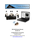
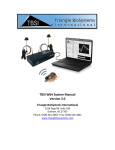
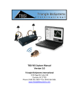
Stimulation User’s Manual Version 2.0 Triangle BioSystems International 2224 Page Rd. Suite 108 Durham, NC 27703 Phone: (919) 361-2663 • Fax: (919) 544-3061 www.trianglebiosystems.com STIMWARE™ User’s Manual Table of Contents Document Overview ................................................................................................................................. - 2 Shipped items list ...................................................................................................................................... - 2 Headstage Pinout ...................................................................................................................................... - 2 Mating Connectors.................................................................................................................................... - 3 Software & Hardware Installation ............................................................................................................ - 3 System Requirements .................................................................................................................. - 3 - StimWare™ Installation................................................................................................................ - 3 - Software Navigation ................................................................................................................................. - 4 Loading/Saving Configurations ................................................................................................................. - 5 Programming the Stim Channels .............................................................................................................. - 7 System Setup and Testing ......................................................................................................................... - 8 Application Notes...................................................................................................................................... - 9 LED Headstage Option ............................................................................................................................ - 10 Electrodes ............................................................................................................................................... - 10 - Version 1.2 -1- 9/2013 STIMWARE™ User’s Manual Document Overview This document will demonstrate how to use the TBSI STIMWARE hardware and software. The program controls a single 2 channel headstage that allows researchers to generate and upload two separately customizable waveform patterns via a simple USB interface. The headstage is battery operated therefore only needs to be connected to USB for charging or pattern download. Shipped items list 2 Channel Stimulation Headstage StimWare Installation CD Trigger/Power Magnet Wand Stim Signal Test Load Board Headstage Pinout NC NC NC NC REF CH2 REF CH1 PRINTED CIRCUIT BOARD Version 1.2 -2- 9/2013 STIMWARE™ User’s Manual Mating Connectors Sullins GRPB042MWCN-RC Sullins LPPB042CFFN-RC Software & Hardware Installation System Requirements The recommended minimum PC requirements are as follows: At least 1.0 GHz Processor 2 GB of storage memory 1 GB RAM (1) USB 2.0 port Windows XP OS Service Pack 2 or later StimWare™ Installation To install and run StimWare™: 1. Insert the StimWare™ installation disc into your computer. Navigate to the 2CH STIMWARE V1.3.4 Installer folder within the installation disc and double click setup.exe, then follow the prompts until installation is complete. 2. Plug the USB cable to both the PC and the headstage hardware. Windows will attempt to find a driver but will not and will pop up an error. 3. Right click on “My computer” and select “Manage” to open the Device Manager. If you do not have “My computer” on your desktop click the start button then right click on “Computer” and select “Device Manager. 4. The headstage will be indicated by a yellow question mark (unidentified device). Right click the unidentified device, select “update driver software”, then “Browse my computer for driver software”. Map to The driver EFM32-Cdc.inf located in the “driver” folder on the installation disk. Follow the driver installation procedure until complete. The headstage should now be indicated by “EFM32-Cdc” under “COM and LTP”. Version 1.2 -3- 9/2013 STIMWARE™ User’s Manual Software Navigation Launch the StimWare software application. StimWare is in ‘Run’ mode once launched. Version 1.2 -4- 9/2013 STIMWARE™ User’s Manual Loading/Saving Configurations Click the “OPEN” button to Explore config files. Default parameters are loaded into StimWare from the configuration (.ini) file located on your computer: C:\Program Files (x86)\2CH STIMWARE V1.3.4 Version 1.2 -5- 9/2013 STIMWARE™ User’s Manual Customized pattern parameters can be saved by pressing the ‘Save As’ button. The new configuration file, by default, will be saved to C:\Program Files(x86)\2CH STIMWARE V1.3.4 Version 1.2 -6- 9/2013 STIMWARE™ User’s Manual Programming the Stim Channels The two stim channels can be enabled and programmed separately from each other. To enable a channel, select the checkbox next to its name. A channel that is unchecked will not output any signal, so it may be advantageous to disable an unused channel to conserve battery life. The graphics in the StimWare interface are intended as conceptual references and do not reflect the actual pattern set by the user-defined parameters. The Initial Delay (ID) will be executed once at the start of the pattern. By clicking the Balance Charge button, the software will verify and/or balance the current of the individual pulses. Checking the Invert box will change the polarity of the entire signal. To enable higher order tiers, check the box next to its name. Keep unused tiers disabled if they are not in use. Certain parametric limitations are programmed into the software to ensure signal consistency and prevent saturation of the headstage amplifiers. If a parameter has exceeded its allowed range (ex. a frequency is set too high in a higher order tier), it will automatically be reset to its highest allowed value. PI1 and PI2 can’t exceed 1000uA. PD1 and PD2 can’t be lower than 50uS. Version 1.2 -7- 9/2013 STIMWARE™ User’s Manual System Setup and Testing Below are instructions to verify pattern transfer to the headstage and signal output: 1) Connect headstage to computer via USB cable Open the StimWare program application. If the headstage is successfully recognized by your computer, the top indicator LED on the front of the headstage will alight green. 2) Generate and upload pattern in StimWare Choose the stim signal parameters you wish to upload to the headstage. (Refer to the Software Navigation section of this document for more pattern programming instructions.) When finished, click the UPLOAD button to send the pattern data to the headstage (this will take no more than a split second to upload). Disconnect the headstage from the computer after uploading. The headstage will be in sleep mode upon disconnecting. 3) Activate and view stim pattern The bottom LED on the front of the headstage will blink yellow once if it is on and twice if it is in standby mode. There will be a 5 second pause between the single or double blinks. Use the magnetic wand to turn on the headstage. To do this, briefly hold the ‘ON/OFF’ tip of the wand next to the front of the headstage. Use the ‘STIM’ tip of the wand to activate the uploaded stim pattern – you will see the bottom LED light up yellow for two seconds if the stim pattern has started executing successfully. Confirm the signal shape coming out of the headstage with an oscilloscope or similar device. The entire pattern will execute once, and then the headstage will go into standby mode. Version 1.2 -8- 9/2013 STIMWARE™ User’s Manual USB Connection Indicator ON, STANDBY, STIM, LOW BATTERY Indicator Application Notes Charging the Headstage Lithium Ion Battery The wireless stimulator headstage includes an integrated rechargeable battery which should be recharged when not in use. Recharging is accomplished by the following procedure: 1. Connect the headstage to your computer using the included USB cable. 2. Execute the StimWare software, then click the Charge Battery button. 3. The indicator LED on the back side of the headstage will alight red when the battery is charging but not full. The LED will change to green when the battery is fully recharged. A completely drained battery will become fully charged in an hour. BATTERY CHARGING Indicator Version 1.2 -9- 9/2013 STIMWARE™ User’s Manual LED Headstage Option Red, blue and green mountable LED options are available for the 2 channel stimulator headstage. The LEDs are placed facing upward on the top of the headstage and are bright enough to allow for most video tracking applications. The LEDs will turn on with the headstage is turned on. Installation of LEDs on the headstage reduces battery life by 15%. Electrodes Microprobes Inc., NeuroNexus, Neuralynx and CD Neural Technologies offer a variety of electrode arrays that connect to all of our headstages. Version 1.2 - 10 - 9/2013 STIMWARE™ User’s Manual Troubleshooting Problem: The headstage won’t turn on. No LEDs light up. Suggestion: Charge the battery via the USB cable provided with the system. Refer to the section titled Application Notes for charging instructions. Problem: One or more output signals are missing or incorrect. Suggestion: Reupload the stim signal parameters to the headstage with StimWare, making sure to follow all instructions within this manual. Check to make sure that the channels are enabled within the software prior to uploading. Check all equipment used to monitor the signal to ensure continuity. Problem: The LEDs are lit on the headstage but it will not output a signal when touched with the magnetic wand. Suggestion: Make sure the ‘STIM’ tip of the wand is being used to activate the stim signal. Call TBSI customer support at (919) 361-2663 if there are any problems with system setup and function. You can also submit a Technical Issue report on our website here. Document history 1.0 Initial release with Specifications 1.1 Removed Specifications, Added cover page 8/2013 1.2 Updated output pinout, added mating connector part number 9/2013 Version 1.2 - 11 - 9/2013