1
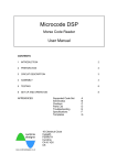
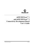
CONTENTS
dsPICflash Programmer
mikroICD (Real-Time Hardware In-Circuit Debugger)
Software Installation
dsPICflash Software
Keyboard Shortcuts and Command Line Parameters
Programmer’s Operation
dsPICflash Programmer Connection
4
6
7
9
10
11
14
4
dsPICflash PROGRAMMER
dsPICflash PROGRAMMER
Along with complementary software, dsPICflash programmer represents an irreplaceable tool
for all those working with dsPIC microcontrollers. By means of this programmer, it is possible
to program almost any dsPIC microcontroller, including those embedded (soldered) in printed
board. The dsPICflash programmer is connected to the microcontroller via five lines. Two of
them are +5V and GND, while others are used for signal transmission:
PGC (program clock);
PGD (program data); and
MCLR (high voltage necessary for Flash memory programming).
These lines are contained within a flat cable ending with a female IDC-10 connector. When
creating a target device, the appropriate 10-pin IDC male connector with the spacing of 2.54
mm between pins should be placed on it. Connector pins should be connected to the microcontroller pins. The position of these pins varies depending on the microcontroller’s type and
package. The exact connection schematics are provided at the end of this manual. During
operation, the dsPICflash programmer may be inactive or active.
Programmer is inactive
A multiplexer within the programmer connects the microcontroller pins to peripheral
components on the printed
board via flat cable. In this
way, the microcontroller directly controls the operation of
device with no impact of the
programmer.
Accordingly,
even the IDC-10 connector is
connected, the dsPICflash
programmer does not affect
device operation.
By clicking the WRITE
option, a multiplexer
within programmer disconnects the microcontroller pins from the rest
of on-board electronics.
It allows programming
of the microcontroller
by using PGC, PGD
and MCLR signals.
When
programming
process is completed,
dsPICflash automatically changes its state
and becomes inactive.
If the target board has its own 5V power supply, it can also be used for powering the
dsPICflash programmer. In this case, it is necessary to open dsPICflash programmer plastic
case and remove the jumper for power supply selection. Otherwise, if the target board does
not have its own power supply source, the jumper should be left on. In this case, the programmer, microcontroller and whole electronics are powered via programmer USB cable which
connects programmer to PC. Any other power supply on the target board must be suspended.
This figure illustrates the position of jumper when the target board and programmer are powered via USB cable.
This figure illustrates the programmer with no jumper for
power supply selection. In this case the programmer is powered by the target board which has its own power supply.
5
dsPICflash PROGRAMMER
Programmer is active
m i k r oI C D
6
mikroICD (Real-Time Hardware In-Circuit Debugger)
mikroICD is a highly effective tool for real-time debugging on hardware level. It enables you
to monitor all its registers and input/output pins while the program is running. mikroICD may
be used with any dsPIC compiler designed by MikroElektronika (mikroC, mikroBasic or
mikroPascal). In order to enable this mode, first select the ICD Debug option within the compiler. Compile the program into machine code and program dsPIC microcontroller after that.
Lastly, select the appropriate debugger- mikroICD Debugger.
mikroICD debugger uses dsPICflash programmer to communicate to the microcontroller and
supports common debugger commands:
Start Debugger
Run/ Pause Debugger
Toggle Breakpoints
Run to cursor
Step Into
Step Over
Flush RAM
Stop Debugger
Note:
[F9]
[F6]
[F5]
[F4]
[F7]
[F8]
[F2]
[Ctrl+F2]
For more information on how to use mikroICD debugger refer to the appropriate documentation. All necessary information may also be found in HELP contained in the
specified compilers.
SOFTWARE INSTALLATION
7
Insert the product CD into your PC drive. After a
few seconds, a list with all MikroElektronika products will appear on the screen. To start installation
of dsPICflash software, click on the setup icon:
dsPICFlash2 software for Windows
You can also download dsPICFlash_setup.exe
free of charge from our web site. In this case,
you should start the installation from your hard
drive. A welcome window will appear on your
screen. Click ‘Next’ to proceed with installation.
Step 2: License Agreement
Prior to starting the installation, please review
the License terms. To accept them, select the
option ‘I accept the terms in the License Agreement’ and click ‘Next’.
Step 3: Choose Components
For the sake of simplicity, this step of installation
offers you only one component to select. Click
‘Next’.
Note:
Make sure that dsPICflash programmer is not connected to the PC during dsPICflash
software installation.
SOFTWARE INSTALLATION
Step 1: Start installation
SOFTWARE INSTALLATION
8
Step 4: Choose Install Location
Now you should specify a folder to install the
program in. If you want to install the program in
the folder different from default, click ‘Browse’
and select another folder on hard disc. Then
click ‘Next’. If you choose default folder, the program will be installed in the following destination:
C:\Program Files\Mikroelektronika\dsPICFLASH
Step 5: Installation Details
dsPICflash installation will start in this step and
its progress will be shown on the screen. If you
are interested in details about the installation
click the ‘Show details’ button.
Step 6: Finish
You will be notified by a window, shown in figure
on the right, that Windows has successfully
installed dsPICflash. Click ‘Finish’ to complete
the installation process.
dsPICflash SOFTWARE
9
Run dsPICflash from your PC. Click
the Device option and select the
appropriate microcontroller to program. dsPICflash will automatically
set parameters for working with the
specified microcontroller.
Step 2: Load HEX file
Click the Load HEX option which opens the
window shown in figure on the right. Select
the appropriate executable file (has extension
.HEX in its name) and click the Open option.
In this way, the file will be loaded into programmer buffer. On the basis of control bits
stored in the HEX file, dsPICflash will do all
necessary settings.
Step 3: Write program
Click the Write option in the upper
right corner of the working window
to start programming the microcontroller. The programming progress
will be shown in the right bottom
corner of the working window.
dsPICflash SOFTWARE
Step 1: Run dsPICflash
programmer
10
KEYBOARD SHORTCUTS AND COMMAND LINE PARAMETER
dsPICflash SOFTWARE
Keyboard Shortcuts
Command Line
Erase
Blank check
Write
Verify
Read
Change MCU
Save
Open (Load)
Reload
Alternatively, you can use dsPICflash programmer from the command line.
It will enable you to use dsPICflash programmer from some other software,
compiler etc. Here is the list with command line parameters:
-w
-v
-e
-r
-p
-f
-b
-q
Example 1
Alt-E
Alt-B
Alt-W
Alt-V
Alt-R
Alt-D
Ctrl-S
Ctrl-O
Ctrl-R
Write to dsPIC
Verify
Erase dsPIC
Read from dsPIC
dsPIC name (for example: P30F4013, P30F3014...)
File name (must be enclosed with " “)
Blank check
Close dsPICflash after programming
dspicflash2.exe -w -pdsPIC30F4013 -v -f"C:\somefile.hex"
This will program the dsPIC using C:\somefile.hex. Immediately after
write, it will verify loaded file.
Example 2
dspicflash2.exe -r -pdsPIC30F4013
This will read the dsPIC program memory.
Example 3
dspicflash2.exe -e -pdsPIC30F4013
This will erase program from the dsPIC microcontroller.
A dsPIC microcontroller programming is performed by using signals Vpp, PGC and PGD from
the dsPICflash programmer. They are brought to the MCLR, RB6 and RB7 pins. In addition,
the microcontroller pins VCC and GND must be supplied with voltage. In order to enable programming to run without errors, make sure that these pins are not connected to other electronic components. Otherwise, during normal operation, such connection must be established
as per project.
Since the microcontroller is soldered on the printed board (with no use of socket), it is necessary to switch these pins by using jumpers. For this reason, you must not forget to provide
space for embedding 5 jumpers when designing a device. They should be embedded
between pins for programming and components connected to these pins.
11
PROGRAMMER’S OPERATION
PROGRAMMER’S OPERATION
PROGRAMMER’S OPERATION
12
Instead of five independent jumpers, you should place a male IDC-10 connector with the
spacing of 2.54mm between pins. During normal operation, its pins must be linked as shown
in figure below. In this way, the microcontroller pins are connected to the rest of on-board electronics. Refer to the Figure below.
During programming, the same connector is used to bring signal from the programmer. To
enable it, you have to remove jumpers from the board. Instead of them, place a programmer
female connector over the on-board male connector.
13
PROGRAMMER’S OPERATION
On-board IDC-10 male connector. Jumpers are removed to enable
connection to the dsPICflash programmer.
Apart from programming the microcontroller, dsPICflash also enables In Circuit Debugger
contained in all compilers designed by MikroElektronika. This program enables the microcontroller to operate in real environment and execute instructions step by step. It also enables the
user to simultaneously monitor all MCU registers while the program is running.
Note:
In-Circuit Debugger cannot monitor the state of the RB6 and RB7 pins since they are
used for communication to the programmer.
dsPICflash PROGRAMMER CONNECTION
14
dsPICflash PROGRAMMER CONNECTION
In order to enable a dsPIC microcontroller programming via dsPICflash programmer it is necessary to connect them. One of the possibilities of such connection is by using a male IDC10 connector. For this reason, it is necessary to provide space on printed board for this connector when designing a device. Pins of this connector are between the microcontroller pins
(VCC, GND, MCLR, RB6 and RB7) and components they use. The appropriate schematic is
shown in figure below. Once you plug in the dsPICflash connector you will be able to program
the microcontroller. Switching the connector pins by jumpers enables device to operate in real
environment as per project.
dsPICflash programmer connector in position for programming or monitoring the operation of the microcontroller by
using In-Circuit Debugger program.
Note:
Figure above illustrates connection between IDC connector and microcontroller pins.
Pay attention to the connection of the VCC pin for power supply.
Connection schematic for on-board male IDC-10 connector and 18-pin dsPIC30F microcontrollers such as dsPIC30F3012, 2011...
Connection schematic for on-board male IDC-10 connector and 28-pin dsPIC30F microcontrollers such as dsPIC30F2012, 3013....
dsPICflash PROGRAMMER CONNECTION
15
dsPICflash PROGRAMMER CONNECTION
16
Connection schematic for on-board male IDC-10 connector and 40-pin dsPIC30F microcontrollers such as dsPIC30F3014, ....
Connection schematic for on-board male IDC-10 connector and 44-pin dsPIC30F microcontrollers such as dsPIC30F3014, ...
Connection schematic for on-board male IDC-10 connector and 64-pin dsPIC30F microcontrollers such as dsPIC30F5015, ...
Connection schematic for on-board male IDC-10 connector and 80-pin dsPIC30F microcontrollers such as dsPIC30F6014, ...
dsPICflash PROGRAMMER CONNECTION
17
dsPICflash PROGRAMMER CONNECTION
18
After the programming process and device development are finished, the male IDC10 connector pins must be switched by jumpers. It enables pins MCLR, RB6 and RB7 to be connected to the rest of on-board electronics, which then enables device to operate normally
without dsPICflash programmer. If needed, the jumpers can be removed and dsPICflash
can be reconnected for reprogramming the chip.
Note:
Target board must not have electrolytic capacitors between the microcontroller pins and
embedded IDC10 connector since the power supply voltage is controlled by the dsPICflash
programmer.