1
Warning
RF Exposure Warning :
※ The radiated output power of this device is below the FCC
radio frequency exposure limits. Nevertheless, the device
should be used in such a manner that the potential for
human contact during normal operation is minimized. In
order to avoid the possibility of exceeding the FCC radio
frequency exposure limit, human proximity to the
antenna should not be less than 6 feet during normal
operation.
Information to user
※ The user’s manual or instruction manual for an intentional
or unintentional radiator shall caution the user that
changes or modifications not expressly approved by the
party responsible for compliance could void the user's
authority to operate the equipment. In cases where the
manual is provided only in a form other than paper, such
as on a computer disk or over the Internet, the
information required by this section may be included in
the manual in that alternative form, provided the user can
reasonably be expected to have the capability to access
information in that form.
Contents
SRG-3150DN Rev.1.1(080409)
SRG-3150DN How to operate basic function and Distress transmitting
1. Set MMSI ID ................................................................................................................. 5
1.1. Self-ID ........................................................................................................ 5
2. SSB mode....................................................................................................................... 5
2.1. Channel Selection ................................................................................ 5
2.2. Frequency Selection ............................................................................ 5
2.3. TX, RX ........................................................................................................ 5
3. DSC mode...................................................................................................................... 5
3.1. Channel Selection ................................................................................ 5
3.2. Frequency Selection ............................................................................ 5
3.3. Call .............................................................................................................. 6
3.4. DSC Message RX Auto Reply ......................................................... 6
4. Distress transmit ......................................................................................................... 6
How to use SN-100 NBDP Terminal
1. Selection of Channel ................................................................................................. 6
2. Selection of Frequency ............................................................................................ 6
3. ARQ mode ..................................................................................................................... 6
4. FEC mode ....................................................................................................................... 6
Chapter 1. Overview ............................................................................................................. 7
1.1. Features ....................................................................................................................... 7
1.2. Basic Components .................................................................................................. 8
Chapter 2. Specifications ..................................................................................................... 9
2.1. General specification ............................................................................................. 9
2.2. MF/HF Transmitter.................................................................................................. 9
2.3. MF/HF Receiver........................................................................................................ 9
2.4. DSC (Digital Selective Calling) W/K Receiver ..........................................10
2.5. MF/HF Control .......................................................................................................10
2.6. Digital Selective Calling (DSC) ........................................................................10
2.7. Narrow band direct Printing (NBDP) ...........................................................11
2.8. Printer (DPU-414)..................................................................................................11
2.9. Printer (OKI) .............................................................................................................11
Chapter 3. Power Supply ................................................................................................... 12
3.1. Power On ..................................................................................................................12
3.2. Operation by AC power.....................................................................................12
3.3. Operation by DC (BATTERY) power..............................................................12
3.4. BATTERY Charging ................................................................................................12
Chapter 4. Front Panel ....................................................................................................... 13
4.1. About Button, Knob, Lamp ..............................................................................13
4.2. LCD display ..............................................................................................................14
4.3. LCD display flow....................................................................................................15
Chapter 5. SSB (TEL) mode ............................................................................................... 16
5.1. SSB Mode .................................................................................................................16
5.2. SSB Menu .................................................................................................................16
(1) Scan Type Set ........................................................................................16
(2) Scan Channel Set .................................................................................16
(3) Scan Frequency Set.............................................................................16
1
(4) SQL Set .....................................................................................................16
(5) LCD Contrast Set ..................................................................................17
(6) Tx Power Set ...........................................................................................17
(7) Manual Tuning.......................................................................................17
(8) ATU – Version (ATU Program Version) .......................................17
(9) Remote Set .............................................................................................17
(10) System Set ............................................................................................17
5.3. Additional Functions (ITU Channel, AM mode, Etc.,) ...........................18
Chapter 6. Digital selective calling (DSC) mode.............................................................. 19
6.1. The selection of DSC mode .............................................................................19
6.2. DSC menu display ................................................................................................19
(1) Distress msg edit .................................................................................19
(2) Individual msg edit. ............................................................................20
(3) Group msg edit.....................................................................................21
(4) Geography msg edit .......................................................................22
(5) Auto/Semi-AT msg edit ....................................................................25
(6) Dist ack/rly msg edit ..........................................................................26
(7) Ordinary ack msg edit .......................................................................28
(8) Display and print msg .......................................................................28
(9) System Set ...............................................................................................28
Chapter 7. Transmitter of distress signal......................................................................... 32
7.1. Test of Distress alert signal ..............................................................................32
Chapter 8. RX of Distress & general call .......................................................................... 33
8.1. RX of Distress Alarm ...........................................................................................33
8.2. General call RX .......................................................................................................34
Chapter 9. How to use print ............................................................................................... 35
9.1. DPU-414 Printer ....................................................................................................35
9.2. OKI Printer................................................................................................................35
Chapter 10. How to use SD-250(Alarm box) .................................................................... 36
10.1. Distress transmitting .........................................................................................36
10.2. In case of receiving distress signal ............................................................36
10.3. Operation by DC (Battery) .............................................................................36
Chapter 11. How to use SP-1250ADC ............................................................................... 36
11.1. Specification .........................................................................................................36
11.2. Input power shift ................................................................................................36
11.3. How to Charge ....................................................................................................36
11.4. In case of over current ....................................................................................36
Chapter 12. Circuit explain ................................................................................................ 37
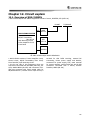
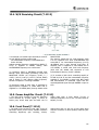
12.1. Overview of SRG-3150DN ..............................................................................37
12.2. CONTROL CIRCUIT (T-1110) .........................................................................38
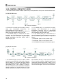
(1) MF/HF RX Circuit..................................................................................38
(2) MF/HF TX Circuit ..................................................................................38
(3) Local Synthesizer Circuit ...................................................................39
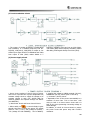
(4) Power Supply Circuit ..........................................................................39
(5) Control Circuit .......................................................................................40
12.3. MH/HF Transmitting Filter Circuit (T-1101) ............................................40
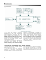
12.4. W/K Receiving Circuit (T-1112) ....................................................................41
12.5. Power Amplifier Circuit (T-1113) .................................................................41
2
12.6. Front Panel (T-1114) .........................................................................................41
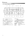
12.7. Function Diagram of Rear Side ...................................................................42
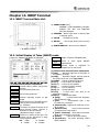
Chapter 13. NBDP Terminal ............................................................................................... 43
13.1. NBDP Terminal Main Unit ..............................................................................43
13.2. Initial Display of Telex (NBDP) mode ........................................................43
(1) Initial screen function explanation ...............................................43
(2) Initial screen function button explanation ...............................43
(3) Control function in Keyboard .........................................................44
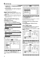
13.3. SettingUpTX/RX Frequency ...........................................................................44
(1) Setting TX frequency ..........................................................................44
(2) Setting Rx frequency ..........................................................................44
(3) Coast Radio Station TX/RX frequency set up .........................44
(4) Setting TX/RX Freq. by calling channel .....................................44
13.4. [ARQ] mode ..........................................................................................................44
(1) Connecting with the other station by ARQ mode. ..............44
(2) Connecting specific station .............................................................45
(3) Communication in ARQ mode ......................................................45
(4) Transmitting file ....................................................................................46
(5) Transmitting of Macro Command ................................................46
13.5. [FEC] mode ............................................................................................................46
(1) Connecting the other station by Selective FEC mode. ......46
(2) Connecting with the other station by collective FEC mode. .......47
(3) Communication in FEC mode ........................................................47
(4) Receiving of FEC mode .....................................................................47
(5) Transmitting file ....................................................................................48
(6) Transmitting of Macro Command ................................................48
13.6. Other sea station or ship station edit & resister frequency ..........48
13.7. Station print (Counter party & Frequency print) ................................49
13.8. Registration of macro command ................................................................49
13.9. Editor mode ..........................................................................................................49
13.10. Initial setting of system set.........................................................................50
(1) Setting of [0. ARQ/FEC 4~ or 5~digit ID] ................................50
(2) Setting of [1. ARQ/FEC 9-digit ID] ...............................................50
(3) Setting of [2. Answer Back Code] ................................................50
(4) Setting of [3. Collective FEC Receiving] .....................................50
(5) Setting of [4. Maximum FEC Error Ratio] .................................50
(6) Selecting of [5. NAVTEX Station Selection] .............................51
(7) Selecting of [6. NAVTEX Message Selection] ..........................51
(8) Selecting of [7. NAVTEX ID Data Clear] ....................................51
(9) [8. ID Printing] set up ........................................................................51
(10) [9. Etc. Setting] set up .....................................................................51
13.11. NBDP test ............................................................................................................52
13.12. LCD Off .................................................................................................................52
Chapter 14. NBDP Terminal Circuit................................................................................... 53
14.1. Overview.................................................................................................................53
14.2. Connection board T-020 ................................................................................53
14.3. NBDP receiving unit (T-132) .........................................................................53
14.4. Local Synthesizer board (T-133) ..................................................................53
14.5. Power Circuit (T-025) ........................................................................................53
14.6. Function Diagram of Rear Side ...................................................................53
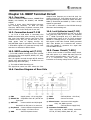
Chapter 15. Troubleshooting ............................................................................................. 54
3
15.1. Overview.................................................................................................................54
15.2. Measuring Instrument......................................................................................54
15.3. Maintenance & repair of SRG-3150DN ...................................................54
(1) Antenna ....................................................................................................54
(2) Power Supply .........................................................................................54
(3) Transmitter ..............................................................................................54
(4) Receiver ....................................................................................................54
(5) DSC Receiver ..........................................................................................54
(6) Switch and Display ..............................................................................55
15.4. NBDP SN-100.......................................................................................................55
(1) Power Supply .........................................................................................55
(2) Screen Display .......................................................................................55
(3) NBDP Data Receiving .........................................................................55
(4) NBDP Data Transmitting ...................................................................55
15.5. Modulation of simple modulator ...............................................................55
15.6. Caution ....................................................................................................................55
Chapter 16. Circuit Diagram & External Diagram ............................................................ 56
4
SRG-3150DN How to operate basic function and Distress transmitting
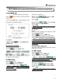
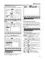
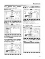
1. Set MMSI ID
(Maritime Mobile Service Identity)
• Press
button and ON, It stop at the below
initial display,
• Then input SELF ID or handle dial/key of the
2.2. Frequency Selection
1)Press twice(
)and select to [TX]
Input frequency by [No. button]
press
.
2) Press twice (
)and select to [RX]
Input frequency by [No. button]
front panel to be operated regularly.
press
.
[ Ref. ] ☞ Missing frequency range, Cannot be
input with alarm sound.
2.3. TX, RX
1) TX
• Can use it after inputting to the frequency TX/RX
that want to communicate.
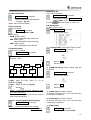
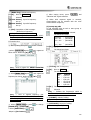
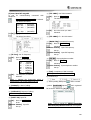
< Initial Screen >
1.1. Self-ID
• [DSC] mode
'1.Self ID set'
/ '9. SYSTEM SET' /
Ex) Input ID 111100000 :
Press any key on the initial screen
Press
2) Received gain adjustment
• Be easy to hear on condition of low noise as down
GAIN and up VOLUME.
to go to [DSC] mode
twice Press(
)and then go
out to 'Main Menu'. (Indicated MMSI Number in
the right side on the bottom)
2. SSB mode
2.1. Channel Selection
• Press
to go to [SSB] mode
select to the channel by dial [CH]
[ Ref. ] ☞ Press twice (
) and
select to [CH]input channel with [No. button]
and then press
.
• Press
to go to [SSB] mode
input the frequency that want to communicate
Press [Mike switch(PTT)] and communicate.
[ Ref. ] ☞ Don’t have a ATU Tunning date
valor of the first channel, ATU Tuning run
automatically to the emergency TX(2,182 /
2,1875 / 4,2075 / 6,312 / 8,4145 / 12,477 /
16,8045 kHz).
3. DSC mode
3.1. Channel Selection
• Press
to go to [DSC] mode
select to the channel by dial [CH]
[ Ref. ] ☞ Press twice (
) and
select to the channel [CH] and input the wanted
channel by[Number]and then press
.
3.2. Frequency Selection
• Press twice (
) and select [TX]
Input the wanted frequency by [No. button]
press
.
[ Ref. ] ☞ Missing frequency range, Cannot be
input with alarm sound.
5
3.3. Call
• Press
to go to [DSC] mode
select to the channel by dial [CH]
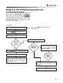
4. Distress transmit
4.1.
Transmit
signal(DISTRESS)
Emergency Transmitter KEY
(1) Hold on 3 seconds
transmit signal.
by
[DISTRESS] and then
3.4. DSC Message RX Auto Reply
• When receive DSC message and Auto ACK on, can
work automatic answer.
• When receive DSC but Auto ACK off and then
don’t work automatic answer.
(2) If you don’t have any reply, flicker the
red[DISTS]display as follow on screen and transmit
channel from 1 to 6 after 4 minutes(3min.and
30sec ~ 4min.40sec.).
(1) How to set
(3) Press
and then stop to transmit.
[DSC] mode press
/ ‘9.SYSTEM SET’
/ ‘0.Etc Set’ / ‘4.Auto Ack’ and finished
setting.
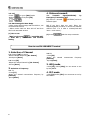
How to use SN-100 NBDP Terminal
1. Selection of Channel
1.1. Change [CH] on screen
Select wanted channel by [No. button]
and press [Enter]
1.2. Press [F6]
Input the wanted channel by [No. button]
Press [Enter]
2. Selection of Frequency
2.1. TX
• Press[F7]
input the wanted communicate frequency by
[Number]
press[Enter]
6
2.2. RX
• Press[F8]
input the wanted
[Number]
press[Enter]
communicate
frequency
3. ARQ mode
• Hold [F2], Select [ARQ] You can access to one
by ARQ MODE.
4. FEC mode
• Hold [F2], Select [FEC] You can access to one by
FEC MODE.
Chapter 1. Overview
• GMDSS(Global Maritime Distress and Safety
System) is an internationally recognized distress
and radio communication safety system for ships
replacing the previous ship to ship safety system,
which relied on a manual Morse code system on
500 kHz and voice radiotelephony on Channel 16
and 2182 kHz. The GMDSS is an automated ship to
shore system using satellites and digital selective
calling technology.
The GMDSS is mandated for ships internationally by
the International Maritime Organization (IMO)
Safety of Life at Sea Convention (SOLAS), 1974, as
amended in 1988, and carries the force of an
international treaty.
• SRG-3150 and SN-100 are composed of MF/HF
transceiver, DSC, DSC W/K Receiver, NBDP,
Automatic alarm telephone for suitable automatic
digital communication at the distress and
safety/normal situation.
SN-100 uses being connected to Transceiver(SRG3150DN), output sub-carrier signal to transmit
NBDP data, displays the information on the display
which is demodulated RX signal receiving from
antennas.
• SRG-3150DN frequency range :
TX : 1.6MHz~27.5MHz
RX : 500kHz~29.99999MHz
• Type of Frequency/Power :
J3E : 150W(HIGH)/100W(MID)/50W(LOW),
F1B : 100W(HIGH&MID)/75W(LOW).
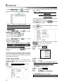
1.1. Features
(1) Possible Range
• Because MF/HF Transceiver(SRG-3150DN), DSC
W/K Receiver, DSC, Distress alarm telephone is built
in SRG-3150DN, You are able to use itself without
NBDP terminal(SN-100). NBDP function is worked
by connecting SN-100 terminal, However it is not
available to use NBDP terminal only.
(2) Total Control System
• SRG-3150DN is set up with the major modules
combined as one unit or circuits within a single
cabinet. Thus, it is possible to rationalize the total
control system by interlinking the respective module
controls.
• And narrow band direct printing is available by
connecting NBDP unit(SN-100) to SRG-3150DN
simply.
(3) User Friendly
• All general operation such as communication,
controls and monitoring, are performed by SRG3150DN, NBDP Terminal and printer which is
installed in a convenient place.
(4) Configuration
• SRG-3150DN consists of one unit; therefore a
large space is not required for installation and
operation.
• SN-100 Terminal is able to use by connecting with
SRG-3150DN cable.
(5) Trustworthy
Adopted new DDS (Direct Digital Synthesize) and
improved the quality of sound, trustworthy, stability.
(6) Construction
• In order to endure in bad condition of marine
environment, hard aluminum body is manufactured.
(7) External Shape
• Channel, Frequency, Transmitting and receiving
conditions can be seen on large LCD at one sight.
And each key is made by soft rubber material. It
has stylish shape and makes you feel comfortable
when you press the button, Further there is
frequency sheet for users. SN-100 NBDP Terminal
has large, thin, colorful LCD and convenient
keyboard.
7
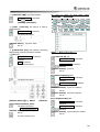
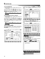
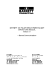
1.2. Basic Components
• This equipment is composed of SRG-3150DN and SN-100(NBDP), each item is made by functional PCB and
sorted by standard and option.
<< Standard Components List >>
Description
No.
1.
MF/HF-DSC 송 수신기
Model
SRG-3150DN
Remark
Q’ty
1set
(1)
MAIN BOARD
T - 1110
1
(2)
TX FILTER
T - 1101
1
SRG-3150DN
(3)
W/K RX
T - 1112
1
Assembly
(4)
TX PA
T - 1113
1
(5)
KEY BOARD
T - 1114
1
(Installation
material included)
2.
Automatic Antenna Tuner
SAT-100
1
3.
HAND MIC
SM-1150
1
4.
Accessory
SSB-A-C,SRG-2050D-PC
1set
5.
User, Installation Manual
SRG-3150DN(Eng)
1
<< Options Components List >>
Description
No.
8
Model
Remark
Q’ty
1.
EMG Light
EMG-Light
1
2.
External Speaker
SS-6000
1
3.
Power Supply
SP-1250ADC
1
4.
NBDP Teminail
SN-100
1set
(1)
Connection Board
T - 130
1
(2)
NBDP 수신부
T - 132
1
(3)
NBDP PLL
T - 133
1
(4)
전원부
T - 025
1
(5)
CPU Board
G-1151
1
5.
KEY Board
SPR8695
1
6.
MF/HF Distress Box
SD-250
1
7.
Printer
DPU-414
1
8
WHIP ANT (TX)
SAN-308
9.
WHIP ANT (RX)
SAN-30R
1
1
SN-100 Assembly
(Installation
material included)
(SCN-16-5P included)
(Installation
material included)
(or OKI Printer)
(8m)
(6m)
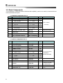
Chapter 2. Specifications
2.1. General specification
• This radio equipment SRG-3150DN has been
tested by the recommendation standard of IMO.
(1) Power Supply (SP-1250ADC)
AC 100-120/200-240V, 50/60Hz, 6% single-phase,
DC24V Power Supply : 1200VA (Max)
(2) Consumption Current: DC24V ±15%
Receiving: 2.5A, at transmitting: 15A (Max)
(3) Frequency Selection
a) ITU CHANNEL (Maritime Mobile) 271
b) 299 USER CHANNEL (Editable at the screen)
or set frequency directly by keyboard.
c) DSC CHANNEL 2187.5, 4207.5, 6312, 8414.5,
12577, 16804.5 kHz (FIB) is scan receiving all
the time.
d) DSC Channel 13EA (Editable).
(4) Frequency Switching Time:
Between CHANNEL - within 5sec,
Between BAND - within 15sec
(Including ANTENNA MATCHING TIME)
(5) Ambient Condition
Temperature : -15℃ ~ +55℃
(7) Number of Channels:
SSB x 299, ITU x 271, DSC x 19
(8) Modulation type:
Low power stage balanced modulation
(9) Occupied Bandwidth:
J3E …… within 3kHz , J2B … within 0.5kHz
(10) Carrier Attenuation : 40dB or more (J3E)
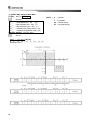
(11) Spurious Attenuation
J3E: 1.5 - 4.5 kHz
31dB or more
4.5 - 7.5 kHz
38dB or more
7.5 kHz or more 43dB or more
F1B: 138Hz
15dB or more
76Hz
31dB or more
500Hz
43dB or more
(12) Overall Frequency:
Deflection 6db max. At 350 - 2,700Hz
(13) Overall Distortion and Noise : 20dB or more
(14) Out Impedance
: 50ohm
(15) Input Low Frequency:
+10dB/-35dB, IMPEDANCE 600 ohm
Humidity: 95%, +55℃
Oscillation : Full amplitude 3.2mm at 5 ~ 12.5Hz
Full amplitude 0.8mm at 12.5 ~ 25Hz
Full amplitude 0.2mm at 25 ~ 50Hz
(6) Dimensions (mm)
SRG-3150DN : 324(W) X 170(H) X 347(D)
SN-100
: 300(W) X 255(H) X 125(D)
(7) Weight
SRG-3150DN about 8.1Kg
SN-100
about 5 Kg
SAT-100
about 3.4Kg
2.3. MF/HF Receiver
2.2. MF/HF Transmitter
(1) Type of Emission : J3E (USB), F1B (FSK)
(2) Type of Communication
: SIMPLEX & SEMI DUPLEX
(3) Frequency Range : TX 1.6MHz - 27.5MHz, 10Hz STEP
(4) Continuous Operating:
Operating for over 8hrs with transmitting for
1minute, stand by for 4minutes.
(5) Output Power:
50 ohm loaded (MF/HF transmitter output)
a) AC : 1.6MHz-27.5MHz 150WPEP
b) DC : 1.6MHz-27.5MHz 75WPEP
c) Power Reduction: 3steps
J3E : 50 / 100 / 150W
F1B : 75 / 100 / 100W
(6) Frequency Deflection:
Below 10Hz (within 0.3ppm)
(1) Type of Emission:
J3E (USB), H3E (only RX), F1B (FSK)
(2) Reception method:
Up conversion double super heterodyne type
using phase-locked digital frequency synthesizer.
First intermediate frequency: 49.455MHz
Second intermediate frequency: 455 kHz
(3) Frequency Range:
500 kHz - 29.99999MHz 10Hz STEP
(4) Voice Output
: Max 5.6W or more
(5) Receiving Sensitivity:
SSB is less 3㎶ at the 500KHz~29.9999MHz
i.e., SSB (S+N+D)/ (N+D) = 20dB,
BAND width 3 kHz, Output 100mW
In case of DSC, NBDP Symbol error rate at a
receiver input voltage of 1㎶ is less than 1 x 10⁻²
i.e., Receiving Mode: FSK, BAND width: 0.3 kHz
(6) 1 signal selectivity
a) 3 kHz FILTER (for SSB) in detailed features
The pass band below 6dB: 2.4 kHz ~ 2.8 kHz
The pass band at an attenuation of 26dB is less
than ±1.7kHz
The pass band at an attenuation of 46dB is less
than ±1.9kHz
The pass band at an attenuation of 66dB is less
than ±2.1kHz
b) 0.3 kHz FILTER (for DSC, NBDP)
Below 6dB of the pass band is 270Hz ~ 300Hz
Attenuation at ±380Hz is 30dB or more
Attenuation at ±550Hz is 60dB or more
9
(7) Clearness: ±120Hz
(8) Overall Distortion & Noise :
With an input voltage of 30uv, the ratio between
an audio frequency output of 1000Hz and its
unwanted component is more than 20db.
(9) AGC characteristics :
Change in audio frequency output for antenna
between 3㎶ and 100mV is 10db or less.
(10) Frequency Stability: within ±10Hz
(11) Image frequency interference ratio :
Above 70dB
(12) Intermediate frequency interference ratio:
Above 80dB
(13) SPURIOUS RESPONSE : Above 70dB
In case of DSC, NBDP
When a wanted signal of 10㎶ and a 31.6㎷
unwanted signal(excluding the range within
750Hz of the wanted signal) whose range of IF
it's three times that of the wanted signal, the
symbol error rate is less than 1 x 10⁻².
(14) Selectivity Suppression : With a wanted signal
of 10㎶ and an unwanted signal that is effect
than 3kHz from the wanted signal, an unwanted
signal input voltage of 10m suppresses the
wanted scanning output to 3db.
In case of DSC, NBDP With a wanted signal of 10
㎶ and 1㎷ unwanted signal 500hz from the
wanted signal, the character error rate is less
than 1 x 10⁻².
(15) Spurious Emission :
The power of emission from air antenna terminal
is less than 4000㎼.
(16) Nominal input load : 50 ohm unbalanced
2.4. DSC (Digital Selective Calling)
W/K Receiver
(1) Type of Emission : F1B
(2) Frequency
: 2 187.5, 4 207.5, 6 312,
8 414.5, 12 577, 16 804.5
kHz
(3) Frequency Stability
: within ±10Hz
(4) SCANNING Reception :
Scanning reception of above frequencies is
continued up to 2sec for each frequency and stop
only when detects a 100 baud dot pattern.
(5) Receiving Sensitivity :
Character error rate is 1 x 10⁻² or less at receiving
input voltage 1㎶.
(6) 1 signal selectivity
6dB bandwidth
: 270 ~ 300Hz
30dB bandwidth
: within ± 380Hz
60dB bandwidth
: within ± 550Hz
(7) Nominal input load
: 50 ohm unbalanced
(8) Display DSC received word :
Maximum 256EA (Figure and word)
10
(9) SPURIOUS RESPONSE:
With a wanted signal of 10㎶ and 31.6㎷ zero
modulated interference signal which excludes the
range within 750hz of the wanted signal, the
character error rate is less than 1 x 10⁻².
(10) Spurious emission:
The power of emission from air antenna terminal
is less than 4000㎼.
2.5. MF/HF Control
(1) Control Items :
MF/HF Transceiver,
DSC, WATCH-KEEPING Receiver,
Frequency Program.
(2) DISTRESS
:
Transmitting 2187.5, 4207.5, 6312, 8414.5, 12577,
16804.5 kHz
(3) Miscellany
:
DISPLAY, Remote Interface, NBDP terminal,
ATU BOX, ALARM BOX, HAND MIC,
Printer, DIMMER
(4) MAIN PROCESSOR : HD64F2506
(5) EEPROM
: 24LC512
(6) Display
: LCD BACK-LIGHT DISPLAY
(7) INTERFACE
RS-232 INTERFACE
: 1 CHANNEL (NBDP)
RS-422/232 INTERFACE : 1 CHANNEL (GPS)
PRINTER INTERFACE : 1 CHANNEL
(CENTRONICS INTERFACE)
2.6. Digital Selective Calling (DSC)
(1) PROTOCOL
(2) EMISSION
(3) Modulator
: CCIR recommendation 493-3 & 541-2
: F1B/J2B 100BAUD
: Output frequency 1700Hz ±85Hz
Output max LEVEL +10dBm
(600 ohm Unbalance/Balance)
(4) Demodulator : Input frequency 1700Hz ±85Hz
Input LEVEL -20dBm ~ +5dBm
(600 ohm Unbalance/Balance)
(5) Processor:
CCIR recommendation 493-3ERROR mark (10 steps)
Correct CLOCK transmitting
CLOCK frequency 14,000 KHz
CLOCK stability within 5 x 10⁻⁶.
(6) DSC Memory Function
• Distress Receipt : 50EA
• Ordinary
: 50EA
• Transmit message : 100EA
2.7. Narrow band direct Printing (NBDP)
(1) Protocol
:
CCIR recommendation 625.476-4.490491.492-3
& CCIR F130
(2) Calling mode :
Individual and group calling with 5 digits and 9
digits select call number.
(3) Operating mode :
ARQ (Auto Repetition Request)
CFEC (Collective Forward ERROR correction)
SFEC (Selective Forward ERROR Correction)
(4) Status Display :
POWER ON, STAND-BY, CALLED, CALLING, FREE.
SIGNAL, ARQ, CFEC, SFEC, SEND, RECEIVER,
PHASING, REPHASING, REPEAT, ERR
(5) Code :
7-bit CORD 4B/3Y constant ratio mark signal
(B:1785Hz, Y:1615Hz)
(6) Memory : 16M
(7) SYSTEM PARAMETER:
OPERATOR DATA is saved at FLASH DISK
PROGRAMING and back-up.
(8) Center frequency : 1700Hz
(9) Frequency SHIFT width: ±85Hz
(10) Modulation Speed :
100BAUD (ARQ, FEC MODE)
(11) Modulation: phase continuity AFSK
(12) Frequency Deflection: within 0.5Hz
(13) Modulation Input :
0dBm, 600ohm Unbalance/Balance
(14) Modulation Output:
0dBm, 600ohm Unbalance/Balance
2.8. Printer (DPU-414)
(1) Specifications
• Typing
: Thermal serial dot matrix
• Total Dots
: 9 x 320 dot / line
• Composition of Dots: 9 x 7 dots wide
• Internal Dots
: 1 dot
• Typing Quantity :
40letters (Standard) 80letters (Shortened)
• Typing Direction : Single / Both Logical seek
(2) Bit-image graphics mode
• Total Dots
: 8 x 320 dot / line
• Typing Direction : Single Logical seek
• Typing width
: 89.6mm
• Typing speed
: Max 52.5cps (Standard
Max 80cps (Shortened)
(3) Ambient
• Temperature: 0℃ ~ 40℃
• Diameter
• Length
: 48mm
: about 28m
(5) Etc
• Power Supply
: DC 6.5 ~ 13.6V
• Dimensions
:160mmx 170mmx 66.5mm
• Weight
: about 580g
• Durability
: about 500,000 lines
("8" 40letters continuously)
(Color thickness 100%)
2.9. Printer (OKI)
(1) Features
• Printer Head
• Speed (CPS)
•
•
•
•
•
•
: 9 pins
: 300CPS (Max speed)
240CPS (High speed)
50CPS (High quality)
Carriage width
: 80letters (10CPI)
Graphic Resolution : 240X216DPI (Max)
Paper Space : From top 15mm (CUT SHEET)
From top 17mm (ROLL)
Interval between letters : 10, 12, 17CPI
Type of Font: Dark, Stress, Thick, Lean
Remember
: 1 Line
(2) Paper
• Dimensions
• Weight
: 241 ~ 254mm
: 35 ~ 52 g/m2
(3) Interface and Standardization
• Standardization
: micro line espon fx ibm
pro printer
• Interface
: centronics parallel
serial rs232c, rs422
(4) Reliability
• Head Life
: 2 billion letters
• Ribbon Life
: 3 million letters
• MTBF
: 6000hrs
(5) Miscellany
• Power
: DC +24V
• Dimensions (HXWXD): 80mmX360mmX275mm
• Weight
: 4.5Kg
• NOTE
: DC available (10~30V DC)
• Humidity: 30% ~ 80% RH(no condensation)
(4) Print Paper
• Model No
• Width
: TP411 - 28CL(TP-411L)
: 112mm
11
Chapter 3. Power Supply
3.1. Power On
3.4. BATTERY Charging
(1) AC power plug put in plug receptacle, connect
the battery with rear socket.
(2) Check the indication of light on: AC IN, DC IN,
and DC OUT of front panel.
(3) Connect cables of SRG-3150DN.
(4) Switch AC and DC power on.
• When connected to AC power, except of switch
on of transmitter power supply AMP power, the
battery is automatically charged, a low current is
supplied to maintain the rated battery voltage.
The charge mode indicator between automatic and
normal is by the charge switch on the system
cabinet.
(5) Push the
button.
3.2. Operation by AC power
• When it comes to supply AC power to the main
unit, it works with AC power automatically. W/K
LED displays the condition that 6 scanning
frequency is working on DSC WKR of the
transceiver. (Refer to "Operation of Distress
Acknowledge Signal" for operation instructions, If
DSC distress or alarm call rings.)
3.3. Operation by DC (BATTERY) power
• When AC power is disconnected, the SRG-3150DN
switches to DC operation and [DC] LED on MF/HF
control panel will light up automatically.
When it is transmitted to DSC, AC signal will be
changed to DC on upside of transceiver LCD display.
Moreover, changing to DC mode will be displayed
on downside of that.
And receiving output is converted to LOW.
12
(1) AUTO MODE: When the battery is out, charged
automatically, Full time charged is set general
mode.
(2) NORMAL MODE: It is charged battery,
regardless battery is status. To use battery longer,
it is required to maintain properly for battery.
Maintaining battery according to the instruction
manual.
(3) OFF MODE: Set the middle of switch between
AUTO & NORMAL.
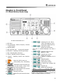
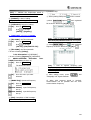
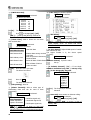
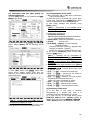
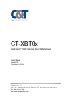
Chapter 4. Front Panel
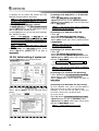
4.1. About Button, Knob, Lamp
< SRG-3150DN Main Unit >
①. KEY Panel
②. Front Panel(LCD) - Mode / Frequency / Channel
/ Other function.
③. Internal Speaker
④. MIC connection jack
- Connect MIC provided.
⑤. Articulation - Adjusting received signal clearly.
: Select ATT in order.
(Display LCD left-bottom)
(The part of received diminution can select 3
levels)
⑥. Gain - Adjusting Gain of Receiver.
⑦. Volume - Adjusting volume of speaker.
⑧. Channel - Adjusting channel and frequency
up/down.
(1)
: Power ON / OFF in main unit.
(2)
: Hold pressing 3sec, Transmitting
Distress signal.
(3)
: Transmitting frequency/channel &
message edited by DSC mode or Stop alarm
sound, Stop distress and call display also.
(4)
: Auto acknowledge for the received
messages ON/OFF in DSC mode.
(5)
: Selecting main menu.
: Hold this key and extend functions
(6)
with random keys.
: Selecting "CH" "TX" "RX" in
Order. (Be available to select
Channel and TX/RX Frequency)
: ON/OFF internal test tone
Signal at 1.4 KHz.
: ON/OFF Scan function.
(Display LCD on top)
(Scan function of channel or frequency can be
started and finished)
: ON/OFF Speaker.
(Display LCD on top)
: Select printer function.
(Can be printed to channel and message that
received frequency)
: ON/OFF N.B.
(Display LCD left-bottom)
[Ref.] ☞ when it is receiving H3E, Noise
Blanker removes noise out of it.
(Noise Blanker: It works to block high level of
impulse of short duration as a device to cut off one
stage from middle frequency of receiver.)
13
: ON/OFF AGC.
(Display LCD left-bottom)
Adjust automatically gain that bundle of
amplification of receiver.
(Auto Gain Control: It means that system maintain
to regardless of changing of strength that input
signal by the book of receiver’s power. As is higher
signaling that incoming to system, diminution
degree of gain is increasing, in conclusion low
signal much more amplifier than high signal).
(14) LED Display
[DISTS]: When receive a Distress signal by W/K
receiver or transmit a Distress alarm signal, be
flickered LED indicator.
[OTHER]: when receive DSC without DISTRESS
signal, be flickered Green LED Indicator.
[TX]
: LED on, transmitting
[W/K]: LED display …… LED on W/K receiver is
operating. (Always Working)
: ON/OFF SQL.
(Display LCD left-bottom)
Delete to noise that occurred on standby receiving
according to signal level.
(*Squelch: mute the equipment and delete to
harassing background noise and unwanted signal
automatic control to the function of receiver or
amplifier exception of incoming signal exceed to a
set point)
4.2. LCD display
: By check mode, RX set displays
RX signal(RxG), Voltage(24V)(VOLT), TX set
displays PA currency(Ic), Antenna currency(ANT),
standing wave ratio(SWR).
front panel.
: Adjust dimmer 5steps in
: Switch AM receiving mode.
: Operating matching channel
before input frequency.
[
[▲]or[▼
]or[▼] : Change of TX Frequency
take turns HIGH / LOW / MID.
(7)
: this button is for selecting to item of
selection on menu mode and for cursor moving
on the display.
(8)
~
: be useful to input the number.
(9)
: Adjust LCD back light (internal) by
4steps. (Holding [FUNC] and press [DIM], Adjust
by 5steps.)
(10)
: Switch SSB & DSC mode.
(Holing [FUNC] and press [MODE], Switch AM
mode.)
[Ref.] ☞ SSB (J3E): use to voice communication
DSC (F1B): use to digital selective
calling communication
(11)
: Matching with user's antenna then
push this button. (Press [FUNC] and hold with
[ATU] for 2sec, Matching all channel.)
(12)
: Cancel set or return precious menu.
(13)
: Execute selecting,
extend...etc at the menu.
14
input,
and
The following information is displayed in general.
(1) Communication Mode (SSB, DSC, AM (only RX)),
Speaker, Acknowledge, Scan, TX power, Time
(UTC GPS being connected)
(2) W/K receiving channel, TX/RX frequency &
channel.
(3) Attenuator (ATT), Noise Blanker (N.B), AGC,
Squelch.
(4) RX signal level, Voltage/Currency (I-c) / (ANTc)/ Standing-wave ratio (Select [F] + [0]), Date,
time (Display UTC, if GPS receiver connected)
(5) Location mark
“MAN”: Manual Input
“GPS”: GPS location (GPS connected)
MMSI (Maritime Mobile Service Identity) ID
(6) Display according to the key input.
(7) Display Description
A)
: Display communication mode
in use.
b)
:
, ON/OFF Speaker
ON - Display
OFF- Display
c) ACK : Display if it selected an automatic
acknowledge in DSC mode.
d) SCN
:
Press
"SCAN" and press
SCAN is finished.
to
start
, and then
e) HIGH : Display transmitting power.
HIGH : SRG-3150DN (J3E:150W, FIB:
100W)
MID :
SRG-3150DN
(J3E:100W,
F1B:100W)
LOW : SRG-3150DN (J3E:50W, F1B:75W)
f) F: Display
is in use or not.
g) AC
: Indicate currency situation to POWER
SUPPLIER (SP-1250ADC).
AC : AC Power Supply.
DC : battery power supply.
H)
i) TX
j) RX
: Display scanning W/K frequencies
(6 channels).
: Transmitting Frequency
: Receiving Frequency
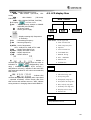
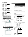
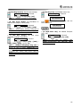
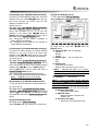
4.3. LCD display flow
MAIN
SSB
DISPLAY
DSC
AM (H3E)
SSB
MAIN MENU 1. Scan Type Set
2. Scan Channel Set
3. Scan Frequency Set
k) ATT3 : Level of attenuation.
ATT1: 10dB, ATT2: 20dB, ATT3: 30dB
l) NB
: Display Noise Blanker set.
m) AGC : Display Auto Gain Control.
n) SQL : Display Squelch set.
o) CH : Display channel.
4. SQL Set
5. LCD Contrast Set
6. TX POWER Set
7. Manual Tuning
8. ATU - VERSION
: indicate a
9. Remote Set
received gain and use to button and can select to
0. SYSTEM Set
p)
indictable to
SWR(standing wave
ratio) / VOLT(PS current) / IC(TX current) /
ANT(Antenna currency), indicate to date and time
and automatic indicate to UTC when connected GPS,
GPS receiver
q)
DSC
MAIN MENU 1. Distress msg edit
2. Individual msg edit
: Indicate GPS
3. Group msg edit
received date (latitude, longitude) when input hand
– operated coordinate, receive directly date from
GPS receiver and indicate screen to “GPS”, indicate
tuning situation in changing channel with MMSI ID.
4. Geography msg edit
5. Auto/Semi-AT msg edit
6. Dist. ack/rly msg edit
7. Ordinary ack msg edit
8. Display & Print msg
9. System Set
AM
*** Only Receive Function
15
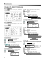
Chapter 5. SSB (TEL) mode
5.1. SSB Mode
Press
to SSB mode.
button on front panel, and then go
[▲][▼]
Move, and select to wanted function,
Selected.
[Number button] Input the value.
Set up.
Press to back to main screen.
[Ref.] ☞ [Start] : Set Start channel.
[End] : Set Last channel.
[Speed] : Set speed of scan channel
(0~9, 0: Fastest, 9: Slowest)
(3) Scan Frequency Set
a) Set value in case of scanning Frequency.
3. Scan Freq. Set is selected.
5.2. SSB Menu
The below box shows.
On SSB Mode when press display to Menu screen
Start
End
Speed
Step
as follow.
.
[▲][▼]
:
:
:
:
500.00
kHz
29,999,99kHz
0
0.1
kHz
Move, and select to wanted function,
Selected.
[Number Button] Input the value.
Set up.
Press to back to main screen.
(1) Scan Type Set
a) Decision scanning channel or frequency.
1. Scan Type is selected.
Select, switching [CH]/ [Freq] in rotation
Return to Main Display.
,
B)
scan to select SACN Type.
[Ref.] ☞ Scan type is [CH], scan channel.
Scan type is [Freq], scan frequency.
(2) Scan Channel Set
a) Fix setting value in case of scanning channel.
(4) SQL Set
a) On standby, if set setting value of SSB particular
sound clearance highly, cannot receive slight signal.
4. SQL Set is selected.
The below box shows.
:10
SQL Sense
Set range : 1 ~ 20
:5
SQL Delay
Set range : 1 ~ 20
[▲][▼]
Move, and select to wanted function,
Selected.
[Number button] Input the value.
2. Scan Ch. Set is selected.
Set up.
The below box shows.
Press to back to main screen.
Start
End
Speed
16
[Ref.] ☞ [Start] : Set Start Frequency.
[End] : Set Last Frequency.
[Speed]: Set speed of scan Frequency.
[Step] : Set step of scan Frequency.
(100HZ/step)
☞ “10.0”at 10kHz step.
: 1
: 299
: 0
[Ref.] ☞ [SQL Sense]: Set sensibility of SQL.
[SQL Delay]: Set delay time of SQL circuit.
(9) Remote Set
a) Set remote operating.
(5) LCD Contrast Set
9. Remote
5. LCD Contrast is selected.
OFF is selected.
Press, can be changed 9.Remote
Display "REM" on the main screen.
Press to change the LCD brightness
From [1] ~ [5] step.
(Higher value and more thicker)
b) Press
ON,
and then change to remote off.
(10) System Set
a) Select system’s value.
(6) Tx Power Set
a) Adjust TX power.
0. System Set is selected.
6.Tx Power is selected.
The below box shows.
Select HIGH / MID / LOW
b) If Tx Power
HIGH, Display "HIGH",
SRG-3150DN(J3E:150W, FIB:100W)
MID, display "MID",
SRG-3150DN(J3E:100W, F1B:100W)
LOW, display "LOW".
SRG-3150DN(J3E:50W, F1B:75W)
① [1.Tuning Clear]: Clear all the memory tuned.
(7) Manual Tuning
a) ATU tuning by manual.
1. Tuning Clear is selected.
The below box shows.
7.Manual Tuning is selected.
The below box shows.
TX Power : Tune
▼
[▼]
Move to Yes
Reboot system.
0.0 uH
0
pF
OFF
0
pF
OFF
OFF
② [2.SSB-CH Clear]: Delete channel data and
set channel.
2. SSB-CH Clear is selected.
The below box shows.
[◀][▶]
Select the point which it is to be
adjusted by[◀][▶]
[▲][▼]
Adjust it’s value by [▲][▼]
Selected.
[Ref.] ☞ press
, the value adjusted is input
and return main menu.
☞ On manual tuning, TX power has not changed
while switching frequency.
(8) ATU – Version (ATU Program Version)
8. ATU---Version is selected.
Selected.
[Ref.] ☞ if ATU DATA cable has any trouble,
Display "Error.”
[▼]
Move to Yes
Reboot system.
③ [3.Data-Set]: Set data in system.
In external GPS Data input, UTC (Universal Time
Coordinated) is displayed.
④ [4.Time-Set]: Set time in system.
In external GPS Data input, UTC (Universal Time
Coordinated) is displayed.
⑤ [5.Key Tone]
5. Key Tone is selected.
Press, can be changed On/Off.
17
⑥ [6.ADC Value]: RXG in first display – Show
selecting ON/OFF.
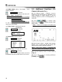
5.3. Additional Functions (ITU
Channel, AM mode, Etc.,)
6. ADC Value is selected.
Press, and then can select IC, ANT, SWR, VOLT.
[Ref.] ☞ RxG : Rx Signal Level
(On setting IC, ANT, SWR, displayed on receiving)
IC
: End Current,
ANT : Antenna Current
SWR : Standing Wave Ratio
VOLT : it means electricity, voltage and
In case of setting IC, ANT and SWR, display
reference to transmitting.
⑦ [7.Auto Tune] : Matching all channels
automatically.
(1) ITU Channel [CH401 - CH2510], it can be
selected by [CH] and [Number] on SSB Mode, if it is
within reference to range channel, it can be
switching channel by dial or button[up/down] of
Hand-MIC.
(2) Press
, it switches [AM]
(H3E) mode, use
, it switches another mode
[SSB or DSC].
[Ref.] ☞ there’s no TX display at the [AM] (only
RX), AGC is set automatically.
7. Auto Tune is selected.
The below box shows.
Freq
Tune
: 2,032.0kHz
: Tuning - - -
⑧ [8.Self Test]: Self test function.
8. Self Test is selected.
The below box
Version
Receiver
Watch-R
Exciter
Tuner
shows.
: 2.0
: good
: good
: good
: good
⑨ [9.Key Test]: Test button the front screen.
9. Key Test is selected.
When press selected button and then
display title that selected button on the screen.
(3) DSC Channel (CH300 ~ CH399), DSC message
appears, goes to mode and edit and change DSC
channel by front knob, hand MIC up/down
[Ref.] ☞ DSC mode / MENU > 2.Individual Msg
Edit / can be edited in DSC Message by [▲] [▼].
(4) It can be moved by cursor on menu mode by
[CH] dial.
(5) If you want to stop on receiving [DISTS] &
[OTHER] press
18
.
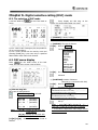
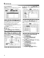
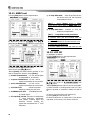
Chapter 6. Digital selective calling (DSC) mode
6.1. The selection of DSC mode
Set DSC Mode by
follow.
on the front Panel as
Press, display can edit msg. on the
screen. (Or can be edited what you want.)
① [FORMAT]: A kind of calling.
Distress : Distress calling(fixed)
② [NATURE]: The type of distress.
[▲][▼]
a) CH1~CH6: In case of emergency only. Not possible to
use in a normal condition.
b) CH7~CH19: Normal can be used by users and
pressing [SCAN] key, it can scan only in specified
data location within CH7~CH19 channel.
Move to NATURE
The below box shows.
Fire, Explosion
Flooding
Collision
Grounding
Listing
Sinking
Adrift
Undesignated
Abandon ship
Piracy/Attack
Man Overboard
6.2. DSC menu display
Press
on the initial screen of the DSC
mode, the sub menu screen is set as follow.
[▲][▼]
Go to the menu you want.
Selected.
③ [POSITION]: Position of distress.
(Auto-set in a connection with GPS)
[▲][▼] Move to POSITION
The below box shows.
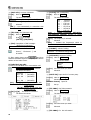
(1) Distress msg edit
a) In case of calling distress.
1.Distress msg edit is selected.
The below box shows.
CH = 300
CH = 301
CH = 302
……
CH = 399
: (NO DATA)
: (NO DATA)
: (NO DATA)
……
: (NO DATA)
[Ref.] ☞ [▲] [▼] : Moving up and down with
1 step channel.
[◀][▶] : Moving up and down with
10 step channels.
[▲][▼][◀][▶] Select Channel that format is
Distress
N__,__,____
/E___,__,____
North latitude(00.00.0000~90.00.0000)
east longitude(000.00.0000~180.00.0000)
S__,__,____
/W___,__,____
South latitude(00.00.0000~90.00.0000)
west longitude(000.00.0000~180.00.0000)
[Number button]
Input the value.
Set up.
[Ref.] ☞ Press [▲] [▼] to change [N_-- E --_]
/ [S -- W_--] / [S – E --] / [N -- W_--] in turns
☞ If the value is beyond the value range, the set
up can not be done.
19
④ [DIST-UTC]: Set time of distress.
① [TX-Freq]: Set TX frequency.
[▲][▼]
[▲][▼]
Move to DIST-UTC
The below box shows.
The below box shows.
01
02
03
04
05
06
19
- - : - - - : Time of Distress(00:00 - 23:59)
[Number. button]
Input the time.
Selected.
[Ref.] ☞ Set automatically in connection with
GPS.
⑤ [TEL CMD]: Set Telecomm and.
[▲][▼]
Move to TEL-CMD
Press
to change
[J3E TP] / [FIB/J2B T].
Move to TX-Freq
:
:
:
:
:
:
2,187.50
4,207.50
6,312.00
8,414.50
12,577.00
16,804.50
8,414.50
[Ref.] ☞ MENU>9.SYSTEM SET>0.Etc.
Set>3.Default Channel possible to select
default TX frequency.
[▲][▼] The frequency is selected.
Selected.
⑥ [EOS]: Completion of DSC message.
(EOS=End of Sequence)
EOS – Set automatically. (fixed)
[Ref.] ☞ Indicate the frequencies which is
memorized by user in DSC mode CH7~19.
② [FORMAT]: A kind of calling.
shown [……File Saved……] and
be saved...
Individual : an individual calling(fixed)
③ [CATEGORY]: Purpose of calling.
b) After setting items press
and then
transmit DISTRESS signal as Frequency that before
edition on DSC main screen.
[▲][▼]
The below box shows.
Routine
Safety
Urgency
(2) Individual msg edit.
a) Used in an individual call or coast station call.
2. Individual mag edit is selected.
[▲][▼]
The below box shows.
CH = 300
CH = 301
CH = 302
……
CH = 399
: (NO DATA)
: (NO DATA)
: (NO DATA)
……
: (NO DATA)
[Ref.] ☞ [▲] [▼] : Moving up and down with
1 step channel.
[◀][▶] : Moving up and down with
10 step channels.
[▲][▼][◀][▶] The channel is selected.
Move to CATEGORY
:
Go to the menu you want.
Selected.
④ [PARTY ID]: Input the ID of counter party.
[▲][▼]
Move to PARTY_ID
Selected.
[Number. button] Input ID.
Set up.
⑤ [TEL CMD1]: Set Telecommand1.
[▲][▼]
Move to TEL CMD1
The below box shows.
The below box shows.
[▲][▼]
Go to the menu you want.
Selected.
⑥ [TEL CMD2]: Fix “No information”
20
⑦ [WORK FRQ]: Operational frequency.
[▲][▼]
c) After setting items, press
“individual call” signal transmits.
Move to WORK FRQ
Selected.
[Number. button] Input TX frequency.
Set up.
[Number. button] Input RX frequency.
Set up.
d) When ACK response signal is received,
communication can be possible with the voice
communication frequency.
(3) Group msg edit
a) Call specified ships as such a same group or
company simultaneously.
⑧ [EOS]: Completion of DSC message.
(EOS=End of Sequence)
ACK RQ : Auto-set.(Fixed)
3. Group msg edit is selected.
The below box shows.
[Ref.] ☞ ACK RQ: Function to request other’s
response. (ACK=Acknowledge=Auto response)
and it is saved.
②select [PARTY-ID]press
: (NO DATA)
: (NO DATA)
: (NO DATA)
……
: (NO DATA)
CH = 300
CH = 301
CH = 302
……
CH = 399
b) Function Keys
① After inputting data press
and
[▲][▼][◀][▶]
The channel is selected.
The below box shows.
and registered
ID list shows select by [▲][▼]
[Ref.] ☞How to register ID: MENU>9.SYSTEM
SET>5.ID/FR/TEL Set>1.ID Edit and register.
① [TX-Freq]: Set TX frequency.
[▲][▼]
Move to TX-Freq
The below box shows.
③ Select[WORK FRQ]press
and registered
01
02
03
04
05
06
19
frequency list shows select by [▲][▼]
[▲][▼]
:
:
:
:
:
:
:
2,187.50
4,207.50
6,312.00
8,414.50
12,577.00
16,804.50
8,414.50
The frequency is selected.
Selected.
[Ref.] ☞ How to register frequency that
communicate with voice: MENU>9.SYSTEM
SET>5.ID/FR/TEL Set>3.Work Frequency
Edit and register.
④ select [WORK FRQ] press
[WORK FRQ] / [POSITION].
Select [POSITION] by
to change
[Ref.] ☞ Indicate the frequencies which is
memorized by user in DSC mode CH7~19.
② [FORMAT]: A kind of calling.
Group : Group calling(fixed)
③ [CATEGORY]: Purpose of calling.
Routine : use general (fixed)
Input by [No. button]
21
④ [PARTY ID] : Input the ID of counter party.
[▲][▼]
Move to PARTY_ID
Selected.
[Number. button] Input ID.
c) After setting items, press
call” signal transmits.
Set up.
⑤ [TEL CMD1]: Set Telecommand1.
[▲][▼]
Move to TEL CMD1
Press
to change
[J3E TP] / [FIB/J2B TTY-FFC].
⑥ [TEL CMD2]: Fix“No information”
⑦ [WORK FRQ]: Operational frequency.
[▲][▼]
[Ref.] ☞ How to register frequency that
communicate with voice: MENU>9.SYSTEM
SET>5.ID/FR/TEL Set>3.Work Frequency
Edit and register.
Move to WORK FRQ
Selected.
[Number. button] Input TX frequency.
Set up.
[Number. button] Input RX frequency.
Set up.
d) When ACK response signal is received,
communication can be possible with the voice
communication frequency.
(4) Geography msg edit
a) calling all ships by coast station call.
Use for communicating with all ships about safety
and others by coast station call.
When coast station call, will be waited
automatically all ships as set voice communication
frequency.
b) calling all ships by base of ships.
It’s no use generally.
Use for emergency or sending
information.
⑧ [EOS]: Completion of DSC message.
(EOS=End of Sequence)
EOS: Auto - set. (fixed)
②select [PARTY-ID]press
The below box shows.
[▲][▼][◀][▶]
ID list shows select by [▲][▼]
The channel is selected.
The below box shows.
[Ref.] ☞How to register ID: MENU>9.SYSTEM
SET>5.ID/FR/TEL Set>1.ID Edit and register.
③ Select[WORK FRQ]press
and registered
① [TX-Freq]: Set TX frequency.
[▲][▼]
Move to TX-Freq
The below box shows.
frequency list shows select by [▲][▼]
01
02
03
04
05
06
19
[▲][▼]
:
:
:
:
:
:
2,187.50
4,207.50
6,312.00
8,414.50
12,577.00
16,804.50
8,414.50
The frequency is selected.
Selected.
22
: (NO DATA)
: (NO DATA)
: (NO DATA)
……
: (NO DATA)
CH = 300
CH = 301
CH = 302
……
CH = 399
and it is saved.
and registered
important
4.Geography msg edit is selected.
b) Function Keys
① After inputting data press
and “group
[Ref.] ☞ Indicate the frequencies which is
memorized by user in DSC mode CH7~19.
c) Function Keys
① After inputting data press
and it is saved.
② [FORMAT]: A kind of calling.
Geography : local calling(fixed)
②select [PARTY-ID]press
③ [CATEGORY]: Purpose of calling.
ID list shows select by [▲][▼]
[▲][▼]
and registered
Move to CATEGORY
Press
to change
[Safety] / [Urgency].
④ [PARTY AD]: reference to 24page.
[Ref.] ☞How to register ID: MENU>9.SYSTEM
SET>5.ID/FR/TEL Set>1.ID Edit and register.
⑤ [TEL CMD1]: Set Telecommand1.
[▲][▼]
Move to TEL CMD1
③ Select[WORK FRQ]press
Press
to change
[J3E TP] / [FIB/J2B TTY-FFC].
and registered
frequency list shows select by [▲][▼]
⑥ [TEL CMD2]: Set Telecommand2.
In case of setting [Safety],
fix“No information”in [CATEGORY].
In case of setting [Urgency] in [CATEGORY].
(☞
MENU>9.SYSTEM
SET>0.Etc.
9.Medi-Trans. Set and select on)
[▲][▼] Move to TEL CMD2
The below box shows.
[▲][▼]
Go to the menu you want.
Selected.
⑦ [WORK FRQ]: Operational frequency.
[▲][▼]
Move to WORK FRQ
Set>
[Ref.] ☞ How to register frequency that
communicate with voice: MENU>9.SYSTEM
SET>5.ID/FR/TEL Set>3.Work Frequency
Edit and register.
c) After setting items, press
“Geography call” signal transmits.
and
d) When ACK response signal is received,
communication can be possible with the voice
communication frequency.
Selected.
[Number. button] input TX frequency.
Set up.
[Number. button] input RX frequency.
Set up.
⑧ [EOS]: Completion of DSC message.
EOS : Auto - set.(fixed)
23
④ [PARTY AD]: Input location data
[▲][▼]
N__
S__
E__
W__
Move to PARTY_AD
Selected.
: North latitude (00 - 90)
(φ )
: South latitude (00 - 90)
(φ )
: East longitude (000 - 180) (λ )
_ : West longitude (000 - 180) (λ )
DA _ _
: Latitude range (Offset Value) (汁φ)
Do _ _ : Longitude range(Offset Value) (汁λ)
[Number. button] Input the value.
Set up.
[Ref.] ☞ every press [▲] [▼]
N_ _ E_ _ / S_ _ W_ _ / S_ _ E_ _ / N_ _ W_ _be
switched in turns.
24
[Ref.] ☞ φ
λ
= Latitude
= Longitude
Δφ = Latitude Range
Δλ = Longitude Range
(5) Auto/Semi-AT msg edit
a) Use for communicating
telephone.
connected
with
⑤ [TEL CMD1]: Set Telecommand1.
[▲][▼]
Move to TEL CMD1
The below box shows.
5.Auto/Semi-AT mag edit is selected.
The below box shows.
: (NO DATA)
: (NO DATA)
: (NO DATA)
……
: (NO DATA)
CH = 300
CH = 301
CH = 302
……
CH = 399
[▲][▼][◀][▶]
[▲][▼]
Selected.
The channel is selected.
The below box shows.
Go to the menu you want.
⑥ [TEL CMD2]: fix “No information”.
⑦ [WORK FRQ]: Operational frequency.
[▲][▼]
Move to WORK FRQ
Selected.
[Number. button] input TX frequency.
Set up.
[Number. button] input RX frequency.
① [TX-Freq]: Set TX frequency.
[▲][▼]
Move to TX-Freq
The below box shows.
01
02
03
04
05
06
19
[▲][▼]
:
:
:
:
:
:
:
2,187.50
4,207.50
6,312.00
8,414.50
12,577.00
16,804.50
8,414.50
The frequency is selected.
Selected.
[Ref.] ☞ Indicate the frequencies which is
memorized by user in DSC mode CH7~19.
② [FORMAT]: A kind of calling.
AT/semi-AT : AT/semi-AT Calling(fixed)
Set up.
⑧ [TEL NO.]: Input telephone number.
[▲][▼]
Move to TEL NO.
Selected.
[Number. button] Input telephone number.
Set up.
⑨ [EOS]: Completion of DSC message.
ACK RQ : Auto-set.(fixed)
b) Function keys
① After inputting data press
and it is saved.
②select [PARTY-ID]press
and registered
ID list shows select by [▲][▼]
③ [CATEGORY]: Purpose of calling.
Routine : use generally (fixed)
④ [PARTY ID]: Input ID.
[▲][▼]
Move to PARTY_ID
Press.
[Number. button] Input ID.
Set up.
[Ref.] ☞How to register ID: MENU>9.SYSTEM
SET>5.ID/FR/TEL Set>1.ID Edit and register.
25
③ Select[WORK FRQ]press
and registered
frequency list shows select by [▲][▼]
b) It is memory channel using from 400 to 499 as
right on the top.
[Ref.] ☞ [▲] [▼] : Moving up and down with
1 step channel.
[◀][▶] : Moving up and down with
10 step channels.
c) When received recently distress signal from other
ship, can check the message.
Press
, input ID press
transmit to Distress signal.
[Ref.] ☞ How to register frequency that
communicate with voice: MENU>9.SYSTEM
SET>5.ID/FR/TEL Set>3.Work Frequency
Edit and register.
④ select [WORK FRQ] press
and then
d) Press
, shown new relay message on screen
and will be editable.
to change
[WORK FRQ] / [POSITION].
Select [POSITION] by
Input by [No. button]
⑤Select [TEL NO.]press
registered Telephone No. List
and
shown
select by [▲][▼]
When can not send distress signal, edit and press
[Ref.] ☞ How to register Telephone No: MENU>
9.SYSTEM
SET>5.ID/FR/TEL
Set>
3.Telephone No. Edit and register)
c) After setting items, press
transmits.
and then can be transmitted.
① [TX-Freq]: Set TX frequency.
[▲][▼]
The below box shows.
and signal
01
02
03
04
05
06
19
d) Coast station call by telephone with calling data,
connect the signal and send ACK signal to ship and
then will be communicated as switching fixed voice
communication frequency.
(6) Dist ack/rly msg edit
a) After inputting the info. , use this menu to
respond to distress signal and manual relay of the
distress message.
6.Dist ack/rly msg edit is selected.
The below box shows.
Move to TX-Freq
[▲][▼]
:
:
:
:
:
:
:
2,187.50
4,207.50
6,312.00
8,414.50
12,577.00
16,804.50
8,414.50
The frequency is selected.
Selected.
[Ref.] ☞ Indicate the frequencies which is
memorized by user in DSC mode CH7~19.
② [FORMAT]: A kind of calling.
[▲][▼]
Move to FORMAT
Press
to change
[Geography] / [Individual].
③ [CATEGORY]: Purpose of calling.
Distress : Distress calling(fixed)
26
④ [PARTY ID] : Input the ID of counter party.
In case of selecting [Individual] in [FORMAT],
input ID
[▲][▼] Move to PARTY_ID
Selected.
[Number. button] Input ID.
Set up.
Select [FORMAT] In case of [Geography],
shown [PARTY-AD], input specific area.
[▲][▼] Move to PARTY_AD
Selected.
[Number. button] Input ID.
Set up.
[Ref.] ☞ MENU>4.Geography msg edit/
PARTY AD and register.
⑧ [POSITION]: Input the Position of the vessel
in distress.
[▲][▼] Move to POSITION
The below box shows.
N__,__,____
/E___,__,____
North latitude(00.00.0000~90.00.0000)
east longitude(000.00.0000~180.00.0000)
S__,__,____
/W___,__,____
South latitude(00.00.0000~90.00.0000)
west longitude(000.00.0000~180.00.0000)
[Number button]
Input the value.
Set up.
[Ref.] ☞ Press [▲] [▼] to change [N_-- E --_]
/ [S -- W_--] / [S – E --] / [N -- W_--] in turns
☞ If the value is beyond the value range, the set
up can not be done.
⑨ [DIST-UTC]: Input the time of distress.
⑤ [TEL CMD]: fix“Distress Relay”
[Ref.] ☞ Distress Relay: in case of relaying
broadcast cause the distance is far from coast
station.
⑥ [DIST ID]: Input the ID of the vessel in
distress.
[▲][▼] Move to DIST ID
Selected.
[Number. button] Input ID.
Set up.
⑦ [NATURE]: The type of distress.
[▲][▼]
Move to NATURE
The below box shows.
Fire, Explosion
Flooding
Collision
Grounding
Listing
Sinking
Adrift
Undesignated
Abandon ship
Piracy/Attack
Man Overboard
[▲][▼]
[▲][▼]
Move to DIST-UTC
The below box shows.
- - : - - - : Time of Distress(00:00 - 23:59)
[Number. button] Input the time.
Selected.
[Ref.] ☞ Set automatically in connection with
GPS.
⑩ [TEL CMD]: Set Telecommand.
[▲][▼]
Move to TEL CMD
Press
to change
[J3E TP] / [FIB/J2B TTY-FFC].
⑪ [EOS]: Completion of DSC message.
(EOS= End of Sequence)
ACK RQ: Auto - set. (fixed)
e) After setting items, press
transmits.
and signal
f) When other ship or coast station send ACK
answer, ship that transmitted distress be going to
receive.
Go to the menu you want.
Selected.
27
(7) Ordinary ack msg edit
a) In case of common answer call.
(9) System Set
a) in case of setting the value of SYSTEM.
7. Ordinary ack msg edit is selected.
9. System Set is selected.
The below box shows.
The below box shows.
b) Memory channel is from 500 to 599 and it shows
on the right top of the box. You can see the general
info. Except distress signal.
[Ref.] ☞ [▲] [▼]: Moving up and down with
1 step channel.
[◀][▶]: Moving up and down with
10 step channels.
c) In this menu press
answered.
and can be
(8) Display and print msg
a) In checking the written messages or auto
printing.
8. Display and print msg is selected.
The below box shows.
① [1.Self ID Set]: Input own ship ID.
1. Self ID Set is selected.
Selected.
[Number. button] Input ID.
Set up.
② [2.Group-ID Set]: Input Group ID.
2. Group ID Set is selected.
Selected.
[Number. button] Input ID.
Set up.
[Ref.] ☞ it’s possible to input just 1 time
because ID is proper number of the ship, so if
you want to make modification, you can reach in
menu by password.
Distributor has a password.
[Ref.] ☞
How to change ID.
to go to [SSB] mode
Press
b) Channels are 300 to 399, can be confirmed on
screen.
[Ref.] ☞ [▲] [▼]: Moving up and down with
1 step channel.
c) If this mode is selected with the printer
connected, printing of the message starts
automatically.
[ ] [ ] [ ] [ ]
dealers)
(Set as ‘ENABLE’)
(Return
screen)
[Self-ID Set]
Press
(Password-Contact
to go to [DSC] mode
Input by [No. button]
[Group-ID Set]
Press
to go to [DSC] mode
Input by [No. button]
28
to
main
③ [3.Dist TEL-CMD]: Set Telecommand.
3. Dist TEL-CMD is selected.
Press
to change
[J3E TP] / [FIB/J2B T].
④ [4.LAT / LON Set]: Set Lat/Lon of GPS by
hand-operation.
4. LAT/LON Set is selected.
Ex) How to input ID and
“SAMYUNG”, “101010000”
ship’s
[▶]
[▶]
[▶]
[▶]
[▶]
name:
[▶]
It is input as below
The below box shows.
[Number button]
Input the value.
Set up.
⑤ [5.ID/FR/TEL Set]: Edit ID/Auto answering
ID/Operating frequency/Telephone number.
[1.ID] edit
5. ID/FR/TEL Set is selected.
[Ref.] ☞ Blank is filling with “0.”
[2. Auto-ack ID] edit
5. ID/FR/TEL Set is selected.
Selected.
Selected.
1. ID is selected.
2. Auto-ack ID is selected.
The below box shows.
Selected.
,
[Number. button] Input ID.
Set up.
[3. Work Frequency] edit
5. ID/FR/TEL Set is selected.
The below box shows.
Selected.
3. Work Frequency is selected.
Selected.
,
[Number. button] Input TX frequency.
Set up.
[Number. button] Input RX frequency.
Set up.
[4. Telephone No.] Edit
[Number button],][▶] Select
move, Select Character, move
The below box shows.
000000000
[Number. button] Input ID.
Set up.
Character,
5. ID/FR/TEL Set is selected.
Selected.
4. Telephone No. is selected.
Selected.
,
[Number. button] Input telephone number.
Set up.
If want to return menu.
29
⑩ [0.Etc. Set]: Set etcetera system.
⑥ [6.WKR Scan Set]
6. WKR Scan Set is selected.
0. Etc. Set is selected.
The below box shows.
The below box shows.
2187.5
4207.5
6312.0
8414.5
12577.5
16804.5
[▲][▼]
on
on
off
on
off
off
The frequency is selected.
Press
to change [on] / [off].
[Ref.] ☞ [2187.5] and [8414.5] must be on.
⑦ [7.Data Clear]: Able to delete the user data
and received data.
7. Data Clear is selected.
The below box shows.
[1. GPS Alarm]
1. GPS Alarm is selected.
Press
to change [on] / [off].
[Ref.] ☞ Regardless of “on” don’t received GPS
signal, display “error” on screen and sound
alarm continually.
4.DSC Channel clear
[2. Scan Speed]: Adjust SCAN speed of usable
DSC channel by user.
The
higher number it is, the slower speed
→Distress data among received
(7~19Ch).
DSC data
2. Scan Speed is selected.
→Data except Distress data among
Received data
Selected.
→Delete all data of DSC Channel[Number. button] Input the value.
5.DSC All Data clear
→Clear
→User
1.DSC Made-File clear
2.DSC Distress clear
3.DSC Ordinary clear
[▲][▼]
DSC data
all data of DSC to
make an initial
Go to the menu you want.
The below box shows.
Set up.
[3. Default Channel]: [SIN] = If set Single
MENU>2.Individual msg edit / 3.Group msg
edit / 4.Use Geography msg edit.
3. Default Channel is selected.
Selected.
[▼]
2,187.5
4,207.5
6,312.0
8,414.5
12,577.0
16,804.5
Move to Yes
The data will be deleted
⑧ [8.ID printing]: Print ID.
⑨ [9.Data Transmit]: Able to select type of
transmitting data and can be used in data
transmitting.
9. Data Transmit is selected.
The below box shows.
→ Send Dot signal only
1.Dot Transmit
2.Mark transmit
→ Send Mark signal only
3.Space Transmit
→ Send space signal only
[Ref.] ☞ select on of them by [▼] [▲]
press
and then it is transmitted immediately
so must be careful.
30
[▲][▼]
The frequency is selected.
Selected.
[4. Auto ACK]: Auto answer on distress calling.
4. Auto ACK is selected.
Press
to change [on] / [off].
[Ref.] ☞ showed “ACK” on screen, in case of
setting “on.”
[5. DSC Msg Receive]: Receive DSC message.
[8. Dist-Key Test]: [DISTRESS] button Test.
5. DSC Msg Receive is selected.
8. Dist-Key Test is selected.
Press
The below box shows.
to change [on] / [off].
[Ref.] ☞ message receiving is not available.
[6. DSC Trans. Mode]: Set DISTRESS TX
channels SIN (single) or MUL (multi).
Press Distress Key
[DISTRESS] for 3 seconds and the
Press
below box shows.
6. DSC Trans Mode is selected.
Press
[Ref.] ☞ Select [MUL], transmit 6channels in
turns and select [SIN] the first channel (2,187.50
KHz) just transmit 5 times repetitively.
[7. DSC Geo. Range]: Set area range
Geography message transmitting.
7. DSC Geo Range is selected.
Press
Press Stop Key
to change [MUL] / [SIN].
to change [120] / [240]. /
[360] / [500] / [600]. (단위는 NM)
Back to Main screen.
[9. Medi-Trans. Set]: Set Medical Transport
[on] / [off].
9. Medi Trans Set is selected.
Press
to change [on] / [off].
[Ref.]
☞
in
case
of
setting
“on”
MENU>4.Geography msg edit>TEL CMD2
and then can be set.
[Ref.] ☞ MENU>4.Geography msg edit on
screen. In case of setting [PARTY-AD] area
range, just input latitude and longitude and press
and then setting value shown that are
inputted of changing value of latitude range and
longitude.
31
Chapter 7. Transmitter of distress signal
7.1. Test of Distress alert signal
(1) Hold on 3 seconds
[DISTRESS] in the
panel, flicker DISTS] LED with alarm and after 3
seconds shown following screen, [DISTS] LED is
lighted and transmit distress location, distress time,
ID.
(2) If don’t have a answer, flicker[DISTS] LED and
shown following screen and then after 4
minutes(3min 30sec ~4min 40sec), transmit
channel 1 ~ 6.
[Ref.] ☞ begin in countdown “Left 04:00.”
(3) If you want to stop to transmit, press
.
Even you press
; channel that is
transmitting will be stop after finishing the
transmitting.
[Ref.] ☞ MENU>9.System Set>1.Self ID
Set If it didn’t set and then flicker [MMSI not
entered] on main screen and can’t transmit.
•Transmit channel 1 ~ 6 as follow.
01
:
2,187.5
02
:
4,207.5
03
:
6,312.0
04
:
8,414.5
05
:
12,577.0
06
:
16,804.5
32
Chapter 8. RX of Distress & general call
8.1. RX of Distress Alarm
(1) Once Distress alarm is received from Distressed
vessel, Red color [DISTS] LED is blinking and
Alarm sounds. To stop the Alarm, press
.
If the CRS reply to the Distress message, the reply
messages appear. (Normally within 3 min.) If the
Distressed vessel receives ACK message from CRS,
follow the CRS instruction.
(2) Flow Chart
Red color [DISTS] LED blinks and
alarm sounds
Distress Alarm RX
Press
button to stop the
alarm.
Check the ID, Distress position on the
saved message screen.
Beyond 150 nm from own ship
Rx ACK
within 3
min. from
CRS.
No
(Alarm sounds)
Yes
Press
Is the
distressed
vessel near
own ship?
Yes
In case own ship go and
rescue the distress vessel,
use radio telephone on the
distress frequency.
button and stop the alarm.
No
Check the saved messages
Keep listening to the distress frequency
(Stand-by for the CRS instruction and
listen to the distress communication
until it finishes.
Check the
distress
vessel is
near own
ship?
No
On the DSC menu, select Distress relay.
After editing, press call button to relay
the distress.
After relay the distress signal, wait for
the reply from CRS.
33
8.2. General call RX
(1) In case [Auto ACK] is [on], if you receive
individual call & group call, automatically, ACK reply
transmits and the frequency is set to TX/RX counter
party.
(2) Flow Chart
RX Individual Call
Green [OTHER] LED blinks and alarm sounds.
In case [Auto ACK] set is [off], press
button and transmit , then the frequency is shifted
to voice communication frequency and the voice
communication is possible.
In case [Auto ACK] setting is [on], ACK reply is transmitted,
Automatically, the frequency is shifted to voice communication
frequency and then voice communication is possible.
Communicate with counter party
Communication ends
34
Chapter 9. How to use print
9.1. DPU-414 Printer
(1) Caution for use
a) The printing paper used for the DPU-414 is a
special kind of paper which turns black by the
thermo chemistry reaction.
Take as following precaution when using the paper.
Store away from Hit, Humidity, light.
Dry hands before handling with the paper
Don't rub the paper with any kind of hard or
coarse materials.
Don't use organic adhesive on the paper. (Instead
of that, water-based starch adhesives or compound
adhesive.)
Don't use adhesive tape on the paper. (However,
using both sides tape is
possible.)
Don't allow the paper to remain in contact with
polyvinyl chloride film for
a long
time.
Don't leave the paper in contact with freshly
coped giazo type or wet
process
paper.
Don't allow the paper to come into contact with
organic solvents.
b) Caution for operation
Check there is a paper in it before use.
Don't turn off while operation and turn off after
PRINT HEAD is at HOME
POSITION.
Printer test function is built-in.
(2) Operation Panels
a) POWER Switch
Switch on the turn this unit on. Printer head do
going and returning once, the paper is fed by one
column.
On condition that main unit of SRG-3150DN is
power on.
b) FEED Switch
Press FEED switch when feed the paper out by
force.
On pressing this switch once, it will be feed once
and on pressing this switch continuously, it will be
kept feeding.
c) CUTTER
Use for cutting the printer paper.
d) Exit of paper - It is the part where the paper is
ejected through it.
e) PAPER COVER
Store up the paper inside it.
(3) Usual operation.
Check the main unit of SRG-3150DN is turned on.
If power on, it is able to print TX/RX DSC MESSAGE
and DATA from SRG-3150DN automatically.
(4) How to store the printer paper roll
a) Cut the printer paper horizontally.
If there is the wrinkle on the paper, it may cause
the paper jam.
< PRINTER PAPER HANDLING >
b) Switch off the printer
c) Open the PAPER COVER and pull out the CENTER
SHAFT.
d) Insert the CENTER SHAFT in the center of the
PAPER ROLL and put the end of the paper into the
way-in of the paper.
e) Switch of the PRINTER and press the FEED KEY
until the paper is hauled.
f) Store up the center shaft and the paper gets out
of the way-out.
g) Press FEED KEY until the end of paper gets out
of the way-out.
h) Close the PAPER COVER and put it down to shut.
9.2. OKI Printer
(1) Common Operation
a) Check out the power of SRG-3150DN connected
with a Printer ON.
b) Pull the switch of the POWER up to turn on the
power.
c) The DATA and DSC MESSAGE transferred from
SRG-3150's transmitting and receiving process is
automatically activated.
(2) PAPER LOADING
a) Place the printer on a slotted printer stand,
carefully aligning the slot in the stand with the
opening in the base of the printer.
b) Place the box of paper under the printer stand.
c) Remove the access cover and lift the column
indicator bar.
d) Open the paper release lever.
e) Insert the first sheet of paper through the
opening in the bottom of the printer.
f) Slide the paper up until it appears in front of
the platen.
g) Lower the column indicator bar.
h) Close the paper release lever.
i) Use the platen knob to advance the paper to
the first printing line.
j) Replace the access cover.
35
Chapter 10. How to use SD-250(Alarm box)
10.1. Distress transmitting
10.2. In case of receiving distress signal
(1) If you press 'Distress key' (Red Button) for 3
sec., it alarms for 3 seconds.
After that, the red light is turned on with bip-sound.
While Distress Key is blinking, transmitting is
started to work and location of disaster, time, ship's
ID are sent to DSC 6 CH in order.
If there is no answer, it does sending till getting an
answer through CH1 to CH 6.
(1) Distress LED blinks and sounds 'bip'.
Check contents displayed on the screen and press
Reset key to stop.
(2) In order to stop the transmitting, press the
'Reset key'.
If distress signal is sent by mistakes, contact to
marine police or station, SAR.
(2) POWER LED keeps blinking while the equipment
is operated by DC power.
10.3. Operation by DC (Battery)
(1) If AC power is turned off, POWER LED is
blinking with "Bip-" sound and presses the Reset
key to stop the sound.
Chapter 11. How to use SP-1250ADC
11.1. Specification
(1) Input
: AC110V / AC220V Conversion Type
(Basis AC220V)
(2) Output : DC24V 50A AVR
(3) Charging current: 20A (Max)
(4) OFF
= Not charging. (Middle of Switch)
(5) NORMAL = Sometimes charge it in the mode.
(1) In case of transmitting SSB, it doesn't be
charged.
(6) In case of checking the charged current, the
switch of CURRENT is turned to CHARGER.
In case of transmitting SSB, the switch is turned
to TX in order to check the current.
REFERENCE: SP-1250ADC is designed to connect
with SSB SRG-3150D only and it is charged as ownbattery power according to the regulation of IMO
(GMDSS).
If it is connected with other SSB equipment, you
should intercept the charging-circuit in SP-1250ADC
and use the high-capacity charging.
(2) There is AUTO / OFF / NORMAL in a switch of
the Charger.
11.4. In case of over current
11.2. Input power shift
In case of AC Power stopping, the buzzer is ringing
and LED green light of AC
OFF is on. In
order to stop the buzzer's ringing, you can turn to
OFF in the
switch of ALARM.
11.3. How to Charge
(3) AUTO = in a long-time charging and it turns to
auto-off when it is completed.
In charging, the LED of CH turns on a light.
In less 23 voltages, auto-charged and finished for
charging in less 0.5 A.
36
In case of being over than 45A current, the LED
red light of OVER CURRENT is on and the buzzer is
ringing. On this occasion, intercept the Power
Switch AC / DC for over than 1 minute and turn the
Power on after deleting the occasion.
Chapter 12. Circuit explain
12.1. Overview of SRG-3150DN
SRG-3150DN MF/HF DSC RADIO equipment consists of circuit, PRINTER, ATU (SAT-100).
RX ANT
W/K
SRG-3150DN SYSTEM
Control circuit
MF/HF Transmitting
filter Circuit
W/K Receiving Circuit
Power Amplifier Circuit
Front Panel
TX/RX ANT
NBDP
SN-100
ATU
SAT-100
PRINTER
< SRG-3150DN MF/HF BLOCK DIAGRAM >
SRG-3150DN consists of Power Amplifier circuit,
Control circuit, MF/HF Transmitting filter circuit,
Front Interface, W/K Receiving Circuit.
At the rear side of this equipment, there are
connectors connected with ATU BOX (SAT-100), SP1250, ALARM BOAX (SD-250) and connectors of PL259 type connected with aerial coaxial cable for
MF/HF transceiver / receiver and for W/K receiver, a
terminal for GPS DATA receiving, external BK
Connecting, Printer power supply and besides,
connectors for power supply, fuse, earth terminal
for system earthing, external SPK jack and D-SUB
connectors connected with a Printer, Remote
Interface, NBDP (SN-100).
37
12.2. CONTROL CIRCUIT (T-1110)
The Control Circuit consists of MF/HF TX/RX circuit, Local Synthesizer circuit, Power circuit and CPU circuit.
(1) MF/HF RX Circuit
< RX BLOCK DIAGRAM >
RX method is a Double Super-heterodyne receiver
using
two
intermediate
frequencies,
1'st
IF=49.455MHz and 2'nd IF=455 KHz.
Receiving signal in whip antenna pass BPF of 9
bands, then after amplify in RF (Q-53) and
in 1'st MIXER (MX2), it is mixed with 1'st LOCAL
frequency and demodulated to a first intermediate
frequency and the intermediate frequency goes
through 49.455MHz X-tal filter (XL5,6) and IF
amplifier (Q22) and
in 2'nd MIXER (MX1), it is mixed with 2'nd LOCAL
frequency and demodulated to a second
intermediate frequency and the demodulated
frequency goes through 455KHz X-tal filter (FL3)
and IF amplifier (Q21,Q23,Q950) and
In 3'rd MIXER (IC15), it is demodulated to a
signal of baseband with BFO (Beat Frequency OSC.).
The demodulated signal is divided to 3 species as
follows.
① Amplifiable signal for inner speaker audio.
② Amplifiable signal for outer speaker audio.
③ FSK MODEM (DSC Signal Demodulation) Signal.
(2) MF/HF TX Circuit
< TX BLOCK DIAGRAM >
The baseband signal comes from MIC or NBDP
terminal is mixed with BPF, 2'nd LOCAL frequency
each in MIXER_3, 2 (IC9, MX1) and goes through
each intermediate frequency filters 455KHz (FL3),
49.455MHz(XL1,XL2), each amplifier (Q36,Q35),
then is modulated to each intermediate frequencies
and the modulated 1'st LOCAL frequency in a final
MIXER_1 (MX2) goes through LPF (Low Pass Filter),
38
BPF of 9bands and then, is input to Power Amplifier
(T-1113) and the sufficient amplified signal in PA
(Power Amp) goes through a final TX filter (T-1111)
and at this time, the harmonic wave (Harmonics) is
removed and the signal comes out thru an antenna.
(3) Local Synthesizer Circuit
The output of 14MHz OCXO(Over Compensated
X-tal Oscillator) is a standard frequency and PLL
IC(IC54), VCO(VCO1), DDS(IC56) is output as 1'st
LOCAL input signal 49.455~79.4549MHz and 7MHz
from output of DDS (IC60) makes 49MHz in 7
frequency multiplier circuit and use as 2'nd LOCAL.
3'rd LOCAL (BFO, Beat Frequency Oscillator) makes
456.4kHz_125Hz signal directly from DDS (IC62).
(4) Power Supply Circuit
Power circuit consists of control circuit of power
unit to turn on/off DC-24V in power amplifiable unit,
constant voltage circuit to supply DC voltage to be
constant voltage in each unit. AUDIO AMP for
external speaker and operate through DC INPUT
(24V BATTERY).
① Main Power Circuit and Power Control Circuit
When switch on
, it controls Relay & goes
through Line Filter to supply the power. The output
power is +15V / +12V / +8V (voltage for printer) /
+7V (Voltage for LCD DIMMER) / +5V. In addition,
it supplies the voltage to NBDP terminal (SN-100),
ALARM BOX (SD-25), Printer (OKI or DPU-414).
② Protection / Sensor Circuit
Operated to turn off the power automatically in a
condition of more than +31V or less than +19V
owing to built in a Power sensor circuit and it is
built in the circuit preventing conversing voltage to
avoid damage.
In addition, it is built in Current Sensor to protect
the power circuit and power amp with 0.0025Ω
resistance.
39
(5) Control Circuit
The control part consists of CPU(IC30),
EEPROM(IC33,37), REAL TIME CLOCK(IC28),
CLOCK Generator(X3), RS-232/422 Data Comdevice, MODEM, Audio amplifier(IC32), I/O
Amplifier, IC(IC22,IC42,IC46,IC48), LCD Contrast /
DIMMER Control Circuit and it controls the whole
operation of the unit with the data signals of RS422/232 from front PANEL operation, external
connecting devices, interface.
CPU device is set by operating PANEL and set
synchronizing circuit responded by receiving
frequency (selecting channel). Then, according to
receiving frequency, set information setting
frequency for SYNTHESIZER or REF/BFO. In
addition, the CPU pass signal (LOCAL CONTROL) to
indicate various information (receiving frequency,
receiving mode, band, width) set by operating
panel of controller unit and transmit in control unit.
Except this function, in case of interception of
power or supply-cease, the CPU control memory
degaussing to be back-up by battery built. Memory
status before normal of power and in case of
normal, possible to rebuild.
12.3. MH/HF Transmitting Filter Circuit (T-1101)
This PCB circuit converts the TX/RX signal as
Relay (RY17) by a TX+ (+12V).
The signal comes from whip antenna is
transferred to a main board (T-1110) through
Diminishable Relay, BK Relay, Over-input protect
40
circuit and it receives a TX signal from PA board (T1113) and select the proper filter in a frequency
band and then, remove the harmonic wave and
transferred to antenna through power sensor circuit.
12.4. W/K Receiving Circuit (T-1112)
RX method is a Double Super-heterodyne receiver
as such MF/HF receiving method and
1'st intermediate frequency is 49.455MHz and
2'nd is 455 KHz.
14MHz standard frequency supplied from MAIN (T1110) is supplied to MIXER making each
SYNTHESIZER frequency into a PCB board.
(1) Receiving signal in ANTENNA terminal pass
through input over-voltage protecting circuit and
BAND-PASS FILTER per frequency (2.187, 5 /
4.207,5 / 6.312 / 8.414,5 / 12.577 / 16.804, 5MHz)
and is closing in DSC distress safety frequency.
FILTER is response in receiving CHANNEL.
(2) Receiving signal to pass filter is amplified by
high-frequency amplifier of width band and is
supplied to 1'st MIXER (MX2) through 20MHz LOW
PASS FILTER.
The signal is mixed with 1'st local frequency (W/K
1'st LO) supplied from inner SYNTHESIZER and
converted to 1'st intermediate frequency (1'st IF)
49.455MHz and it goes through X-tal filter, IF
amplifier, then is supplied to 2'nd MIXER and in
2'nd MIXER, is mixed with 2'nd local frequency
(W/K 2'nd LO) 49MHz and converted to 2'nd
intermediate frequency (2'nd IF) 455KHz.
(3) It consists of AGC circuit controlling amplify of
IF AMP by 2'nd IF and the intermediate frequency
supplied to 3'rd MIXER is mixed with BFO signal
and demodulated to baseband signal and the
output-digitalized signal through MODEM is input to
CPU.
12.5. Power Amplifier Circuit (T-1113)
The PCB circuit consists of PA+24V Switching
circuit effected by TX+KEY signal, 2 pieces of
Drive's part, Power Amp part and after the TX
signal input from a main board (T-1110) is
sufficient amplified, sent to the TX Filter board of
MF/HF (T-1101).
12.6. Front Panel (T-1114)
The PCB circuit consists of LCD, LED, a kind of
tap-switch with a power switch, variable resistance
controlling brightness, gain receiving, volume,
channel dial and it is put into a front panel along
with the connector for inter speaker, hand Mic (SM1150).
41
12.7. Function Diagram of Rear Side
① ANT
② W/K
: IMPEDANCE 50Ω MF/HF TX/RX.
ANT. JACK
: IMPEDANCE 50Ω W/K RX. ANT. JACK
③ TERMINAL(7) : PRINTER POWER (+8V),
GPS DATA, BK+/- Connector
④ ATU
: ATU BOX(SAT-100) connector
(Control Cable)
⑤ AC/DC : Power Supply (SP-1250) connector
(AC/DC Detect)
⑥ ALARM BOX : ALARM BOX(SD-250) connector
42
⑦ PRT or D/L(9) :
PRINTER (OKI / DPU-414) connector or
PROGRAM Down Load connector
⑧ REMOTE(9) : REMOTE INTERFACE connector
⑨ MOD or NBDP(15) : Outer MODEM /
NBDP terminal (SN-100) connector
⑩ SPK JACK : Outer Speaker connector JACK
⑪ EARTH
: SYSTEM GROUND
⑫ +24V
: POWER(+24V) SUPPLY connector
⑬ FUSE
: 30A FUSE
Chapter 13. NBDP Terminal
13.1. NBDP Terminal Main Unit
①. FRONT PANEL (LCD):
CHANNEL, TX/RX FREQUENCY, RF.GAIN,
CLARIFY; ATT, AGC, and FUNCTION
KEYS are displayed.
②. SPEAKER : Alarm rings when it receives data
or warning signal.
③. TX LED
: Red light on TX LED
④. RX LED
: Green light blinks while receiving
data
⑤. POWER SWITCH : SN-100 Power ON/OFF
< NBDP PICTURE >
13.2. Initial Display of Telex (NBDP) mode
Power on, indicate first display as followings
TX Power
AGC
Vol GRAPH
(1) Initial screen function explanation
Indicate calling channel and present
CH
channel
Set transmitting frequency
TX
RX
Set receiving frequency
BAR GRAPH Indicate adjusting portion as Bar
Graph
Adjust
the portion of RF GAIN properly
RF GAIN
using up/down with direction keys.
(0~ 100steps)
The button to adjust the clarity of RX.
CLARIFY
Using direction button, increase or
decrease to gain the best RX.
(Adjustment range: ±10Hz)
Function
to reduce the RX gain. This
ATT
function can be adjusted in 4 steps
using up/down button.
OFF : 0dBm,
2 : 20 dBm
1 : 10dBm,
3 : 30 dBm
Adjust TX power HIGH/MID/LOW
Profit of input signal ON/OFF
automatically.
Volume sound is displayed on
Graphic bar (0~100 levels)
(2) Initial screen function button explanation
[1 DIM]
: Adjust the lightness of back light on
LCD display. (5 LEVEL)
[2 LINK]
: Automatic Repeat request mode &
FEC mode can be set up by [F2] button
[3 COMM] : Call the registered frequency.
[4 VOL-]
: Volume down the speaker.
[5 VOL+] : Volume up the speaker.
[6 CH]
: Set the frequency channel
[7 TX]: TX : Set TX frequency.
[8 Rx]: RX : Set RX frequency.
[9 Tune]
: is used when user want to do
matching to antenna.
[0 Menu] : Indicate Main Menu
0. [ARQ]
: Communicate with Automatic
Repeat Request Mode.
1. [FEC]
: Communicate with 1 way
Forward Error Correction.
2. [Station Edit] : Register the frequency of the
other station.
3. [Station Print]
: Print out the frequency
of registered the other station.
4. [Macro Command] : Write Macro command.
(Write short sentence in 20 words)
5. [Editor]
: Edit file and save content.
6. [System set] : Use while adjusting TELEX
mode condition.
43
7. [NBDP Test]
: Transmitting signals of Dot,
Mark, Space. Use for testing printer and NBDP
TX/RX condition.
8. [LCD-off (F12) : The function of LCD off and
in the case that LCD is off, if any button is
pressed, LCD is on.
(3) Control function in Keyboard
[PgUp] : Adjust channel to next channel. But if
next channel is not registered, it moves to next
channel of it.
[PgDn] : Adjust channel to forward channel. But,
if forward channel is not registered, it moves to
forward channel of it.
13.3. SettingUpTX/RX Frequency
UNIT: kHz
(1) Setting TX frequency
a) Press [F7] button on the keyboard.
b) Input the frequency with [Number button].
[Ref.] ☞ While inputting frequency if press [
],
[
], curser will move.
c) Press [Enter] button.
[Ref.] ☞ Available TX Frequency range: 1.6MHz
~ 27.5MHz.
(2) Setting Rx frequency
a) Press [F8] button.
b) Input the frequency with [Number button].
[Ref.] ☞ While inputting frequency if press [
],
[
], curser will move.
c) Press [Enter] button.
[Ref.] ☞ Available RX Frequency range: 95 KHz
~ 29.99999MHz.
c) Revert the channel you want to communicate
using [
],[
],[
],[
] button.
press [Enter] button.
Set TX/RX frequency to registered freq. on channel
displaying the first display of NBDP.
(4) Setting TX/RX Freq. by calling channel
a) Press [F6].
b) Input the channel with [Number button].
c) Press [Enter] button.
13.4. [ARQ] mode
(1) Connecting with the other station by ARQ mode.
Connecting by present adjusting channel.
a) Press [F2] button on the keyboard and Link
Menu screen shows.
(3) Coast Radio Station TX/RX frequency set
up
a) Press [F3] button, display as followings.
b) Move the cursor with [
]/[
] button to ‘1.
[ARQ]’ press [Enter], then it will be connected
with other party through [ARQ] mode in present
setting Channel.
b) Revert the other station you want to
communicate using [
],[
],[
],[
] button.
press [Enter] button, the following screen will
show.
44
(2) Connecting specific station
a) Call the menu pressing [F10] to call SUB MENU
key.
b) Move the cursor with [
]/[
] button to ‘0.
[ARQ]’ press [Enter] and the following screen
will appear.
c) Revert the other station you want to
communicate using [
],[
],[
],[
] button.
press [Enter] button, the following screen will
show.
[Ref.] ☞ can be back to forward display
pressing [ESC] button.
d) Revert the channel you want to communicate
using [
],[
],[
],[
] button.
press [Enter] button.
e) Call the other station with selected frequency
displaying next [ARQ] mode first display.
[Ref.] ☞ to stop calling, press [F8] and it will
be back to Telex initial screen.
f) If connected, cursor blinks on the left top of the
screen.
(3) Communication in ARQ mode
Perform (1) or (2) and operate as below order.
a) As long as you can connect with the other
station in [ARQ] mode, above screen is displayed.
You can keep communicating in this condition.
b) After typing the message with keyboard, press
[Enter] button.
[Ref.] ☞ Back space - delete one character on
the left. Before you press [Enter] button,
transmitting is not complete.
c) Usable keys in ARQ mode
The usable characters:
ABDCDEFGHIJKLMNOPQRSTUVWXYZ1234567890
-? ().'=/+abcdefghijklmnopqrstuvwxyz
[Back space] : Delete one character on the left
[Enter]
: Send one line.
[Left Shift] + [Space] : Convert language.
(English, Russian)
[Korean] is selected : [Korean] / [English] shift
[English] is selected : [English]
[Russian] is selected : [Russian]/[English] shift
[F1] : [1 WHU] - Demand Answer back code of
the other station.
[F2] : [2 Hereis] - Transmit Answer back code
of yourself.
[F3] : [3 TMS] - Transmit the present time
[F4] : [4 F.send] - Transmit the file written in
edit mode. (Refer to (4) TX of file)
[F5] : [5 Macro] –You can use the sentence no.
Written in Macro Command
(Refer to ‘(5) Macro Command RX)
[F7] : [7 Over] - Convert the direction of
transmitting the message.
[F8] : [8 Stop] - Stop communication.
[F9] : [9 VOL-] – Volume can be reduced.
[F10] : [0 VOL+] – Volume can be increased.
45
(4) Transmitting file
After performing ‘(1)’ or ‘(2)’, operate the unit as
below order.
a) Press Function button [F4] Move the cursor to
the file you want using [
]/[
] button Press
[Enter] button and the file will be transmitted
showing the file contents on the screen.
[Ref.] ☞ pressing [F8] button is able to stop
transmitting.
(5) Transmitting of Macro Command
After performing ‘(1)’ or ‘(2)’, operate the unit as
below order.
a) Press Function button [F5] Move the cursor to
the sentence no. to be transmitted using [
]/[
]
button Press [Enter] button and the sentence
will be transmitted showing the command contents
on the screen.
[Ref.] ☞ pressing [F8] button is able to stop
transmitting.
b) Move the cursor to 2. [FEC] with [
]/[
]
button Press [Enter] and the following screen
shows.
c) Revert the other station you want to
communicate using [
],[
],[
],[
] button.
press [Enter] button, the following screen will
show.
13.5. [FEC] mode
(1) Connecting the other station by Selective
FEC mode.
Communication with present selecting Channel
a) Press [F2] button on the keyboard and Link
Menu screen shows.
[Ref.] ☞ to be back to forward display. Press
[ESC] button.
d) Revert the channel you want to communicate
using [
],[
],[
],[
] button.
press [Enter] button.
e) Call the other station with selected frequency
displaying next [SFEC] mode first display.
[Ref.] ☞ to stop calling, press [F8] and it will
be back to Telex initial screen.
f) If connected, cursor blinks on the left top of the
screen.
46
(2) Connecting with the other station by
collective FEC mode.
a) Press [F10] button on the keyboard and Main
Menu screen shows.
b) Move the cursor to 1. [FEC] with [
]/[
]
button Press [Enter] and the following screen
shows.
c) Press [Esc] button and [CFEC] mode initial
screen shows. Display counter party with the
frequency of the channel which was set up on the
Telex initial screen.
[Ref.] ☞ to stop calling, press [F8], Then it is
changed to first display of Telex.
d) When the call is connected with counter party,
cursor blinks on the top left of message screen.
(3) Communication in FEC mode
After performing ‘(1)’ or ‘(2)’ above, operate the
unit as following order.
a) When the telex is connected with counter party
in FEC mode, initial screen of [CFEC] Mode shows
and the communication starts on this condition...
b) After typing message with keyboard, press
[ENT] to send.
[Ref.] ☞ Transmitting is not available unless
you press [Enter] button.
c) Usable keys in FEC mode
The usable characters:
ABCDEFGHIJKLMNOPQRSTUVWXYZ1234567890
-? ().'=/+abcdefghijklmnopqrstuvwxyz
[Back space] : Delete one character on the left
[Enter]
: Send one line.
[Left Shift] + [Space] : Convert language.
(English, Russian)
[Korean] is selected : [Korean] / [English] shift
[English] is selected : [English]
[Russian] is selected : [Russian]/[English] shift
d) The use of [Function] button on the initial
screen of [FEC] mode.
[Ref.] ☞ Message can be transmitted by
[Function] button on the [FEC] mode initial
screen.
Press the function button Press [Enter] button
to transmit.
Select the function with material Press [Enter]
button to transmit.
[F2] : [2 Hereis] - Transmit Answer back code
of yourself.
[F3] : [3 TMS] - Transmit the present time
[F4] : [4 F.send] - Transmit the file written in
edit mode. (Refer to (5) TX of file)
[F5] : [5 Macro] - Sentence no. made in Macro
Command can be selected and used.
(Refer to‘(6) Macro Command TX article)
[F8] : [8 Stop] - Stop communication.
[F9] : [9 VOL-] – Reduce speaker volume
[F10] : [0 VOL+] – Increase speaker volume
(4) Receiving of FEC mode
a) If the data of FEC mode is received,
automatically, it is printed. And, when it is
completely received, automatically, it is saved.
b) To open the file, on the initial screen, select
[F10][5. Editor] mode [Enter] [F1] (1
Lord) select the file amongRECV 01~RECV 20
Press [Enter] button and you can see the file.
47
(5) Transmitting file
After done above (1) of (2), follow the operation
as below.
a) Press [F4] and below screen is displayed.
Select the file to transmit with [
]/[
] button
press [Enter] button and file will be transmitted
showing the contents of the file on the screen.
b) Move the cursor to 2. Station Edit with
[
]/[
] button Press [Enter] and the following
screen shows.
c) Revert the other station you want to
communicate using [
],[
],[
],[
] button.
press [Enter] button, the following screen will
show.
(6) Transmitting of Macro Command
After performing ‘(1)’ or ‘(2)’ above, operate the
unit as following order.
a) Press [F5]
moves the cursor & select sentence no. with
[
]/[
] button
Press [Enter] and the command will be
transmitted showing the contents of command.
[Ref.] ☞ pressing [F8] is able to stop transmitting.
13.6. Other sea station or ship
station edit & resister frequency
a) Press [F10] button on the keyboard and Main
Menu screen shows.
48
d) Move the cursor to [Station input part]
press [Enter].
e) Input [Station name]
Press [Enter] and it will be saved.
f) Move the cursor to [ID input part]
press [Enter]
g) Input [ID] Press [Enter] and it will be saved.
h) Move the cursor to the [TX] of the channel
press [Enter] button.
I) Input [TX Frequency]
press [Enter] and it will be saved...
j) Move the cursor to [Rx] of the Channel
press [Enter]
k) Input [RX Frequency]
Press [Enter] and it will be saved.
L) Press [ESC] and Main Menu screen shows.
13.7. Station print (Counter
party & Frequency print)
b)Move the cursor to 4. Macro Command with
[
]/[
] button Press [Enter] and the following
screen shows.
a) Press [F10] button on the keyboard and Main
Menu screen shows.
b) Move the cursor to 3. Station Print with
[
]/[
] button Press [Enter] and the following
screen shows.
c) Move the cursor & select the command no. with
[
],[
],[
],[
] button
[Enter]
Type command with keyboard
Press [Enter] and it will be saved.
d) Press [ESC] and Main Menu screen shows.
13.9. Editor mode
a) Press [F10] button on the keyboard and Main
Menu screen shows.
c) Move the cursor to the counter party you want
with [
]/[
] button Press [Enter] and counter
party’s registered contents will be printed out and
will be back to Main Menu.
13.8. Registration of macro command
Can resister TXL number (that is often used) or
abbreviated words in 20 words.
a) Press [F10] button on the keyboard and Main
Menu screen shows.
b)Move the cursor to 5. Editor with [
]/[
]
button Press [Enter] and the following screen
shows.
49
c) Message can be written and revised. Also FEC,
NAVTEX, Received DATA is saved here.
[Ref.] ☞ The Function can be used to make
message using [function key] on the botton of
Edit message screen.
d) Press [F2] input File-Name[Enter]
Select Slot no. on the Slot Number screen
press [Enter] and it will be saved and it will be
back to Edit screen message screen.
e) Press [F1] and you can call the saved message,
FEC, NAVTEX, RX data.
[Ref.] ☞ From Slot 01 ~ to Slot 20 User can
save the file, from RECV 01 to RECV 20, FEC
Received Data, NAVTEX Received Data are
automatically saved.
[Ref.] ☞ Press [ESC] and back to edit msg
screen.
f) Press [F10] and Edit Exit? Screen shows
select YesPress [Enter] and it will back to
Main Menu.
13.10. Initial setting of system set
a) Press [F10] button on the keyboard and
Main Menu screen shows.
(1) Setting of [0. ARQ/FEC 4~ or 5~digit ID]
After ‘(b)’
select [0. ARQ/FEC 4- or 5-digit ID]
[Enter] Input the ID with [Number] button
[Enter] press [ESC] and it will be saved and
back to Main Menu
[Ref.] ☞ this will be done during installation
and the user can not change.
(2) Setting of [1. ARQ/FEC 9-digit ID]
After ‘(b)’
select [1. ARQ/FEC 9-digit ID][Enter]
input the ID with [Number] button[Enter]
press [ESC] button and it will be saved and back
to Main Menu
[Ref.] ☞ this will be set up during installation
and users can not change.
(3) Setting of [2. Answer Back Code]
After ‘(b)’
select [2. Answer Back Code][Enter]
input the code with [Number & Alphabet] button
[Enter]press [ESC] button and it will be saved
and back to Main Menu
ANS/Back code
X ⇒
ex) MMSINo.9 digit
123456789_ABCD_X
[Ref.] ☞ this will be done during installation
and users can not change.
(4) Setting of [3. Collective FEC Receiving]
After ‘(b)’select [3. Collective FEC Receiving]
select [On] or [Off] with [Enter] button
press [ESC] and it will be saved and back to
Main Menu
b)Move the cursor to 6. System Set with [
]/[
]
button Press [Enter] and the following screen
shows.
50
(5) Setting of [4. Maximum FEC Error Ratio]
① If RX character error rate in the FEC MODE is
higher than the set up value, the RX will stop.
(Example, if error rate set up value is 30%, the
error rate is above 30%, the RX will stop.
② How to set up
After ‘(b)’select [4. Maximum FEC Error Ratio]
[Enter]input the ratio by [Number] button
[Enter]press [ESC] button and it will be saved
and back to Main Menu screen.
[Ref.] ☞ Value ranges from 1 to 100.
(6) Selecting of [5. NAVTEX Station Selection]
① Function to select NAVTEX station RX. Select the
character from A to Z with [
]/[
] button and you
can choose whether you receive with the first
character of station or not.
②How to set up
After ‘(b)’select [5. NAVTEX Station Selection]
[Enter]NAVTEX Station Selection Set Up
screen will showset up ‘O / X’ for the first
character of the station with [
]/[
] button &
[Enter] buttonpress [ESC] button and it will be
saved and back to System Setting Menu.
• O : Recognized as the station is possible to
receive NAVTEX broadcasting.
• X : Recognized as the station is not possible to
receive NAVTEX broadcasting
(7) Selecting of [6. NAVTEX Message Selection]
① Function to select whether you receive NAVTEX
message or not. From C, E to Z, select each
character with [
]/[
] button and you can select
whether you receive or not with the first character.
② How to set up
After ‘(b)’select [6. NAVTEX Message Selection]
[Enter]NAVTEX Message Selection set up
screen showsSet up O/X for the message starting
character with [
]/[
] button & [Enter] button
Press [ESC] and it will be saved and back to
System Setting Menu screen.
• O : Recognized as NAVTEX starting message.
• X : Not Recognized as NAVTEX starting message.
[Ref.] ☞ A, B, D is set up as RX always.
(8) Selecting of [7. NAVTEX ID Data Clear]
① Use this menu to delete the received Navtex ID
② How to set up
After ‘(b)’select [7. NAVTEX ID Data Clear]
[Enter] NAVTEX ID Data Clear? Screen shows.
Select YesPress [Enter] and NAVTEX ID Data
will be deleted and back to System Setting Menu
screen.
(9) [8. ID Printing] set up
After ‘(b)’select [8. ID Printing]
press [Enter] and own country ID is printed out.
(10) [9. Etc. Setting] set up
① After ‘(2)’select [9. Etc Setting]
press [Enter] and the following screen will show.
② Items can be reset with [
]/[
] button &
[Enter] button.
• 0. Language Set : Set up Language
Korean
Russian
English
• 1. Printer Type : Set up Printer type
OKI
DPU
• 2. Printer Port :
Local (Main unit printer)
Remote (SN-100 printer) can be set up.
[Ref.] ☞ regarding the above ‘0, 1, 2 article’,
select the item and press [Enter] to shift the
function and select the function you want.
• 3. Date Set
: Set up date
• 4. Time Set
: Set up time
[Ref.] ☞ to set up the above ‘3, 4’, select the
item and press [Enter]input [Number button]
Press [Enter] and it will be saved and input
window will disappear.
• 5. Data Clear : There are sub menu like below.
0. Memory-data Clear
Delete the Station Name.
1. Edit-File Clear
Delete the Macro Command File
& Editor File.
2. FEC-Recv-File Clear
Delete the received FEC-Recv-File.
51
13.11. NBDP test
a) Press [F10] button on the keyboard and
Main Menu screen shows.
⑦ 6. Freq-Shift View : After Freq-Shift Correct,
this shows how well the frequency
compensation is done.
[Ref.] ☞ press [Enter] button or [ESC]
button and it will be back to NBDP Test Menu
screen.
⑧ 7. Freq-Shift Clear : Function to clear the
frequency compensation.
[Ref.] ☞ Freq-Shift Correct precaution
b) Move the cursor to 7. NBDP with [
]/[
]
buttonPress [Enter] and the following screen shows.
① Operate main unit and terminal after full
warm-up
② Perform NBDP RX/TX Test and check it is ok.
③ Check the Freq-Shift View
④ Perform NBDP RX/TX Test and check the test
result is ok.
13.12. LCD Off
(1) Operation on MENU
a) Press [F10] button on the keyboard and
Main Menu screen shows.
c) How to operate NBDP Test function
Select cursor with [
]/[
] button
Press [Enter] and each function operates. If you
want to change the function, press [Enter].
① 0. Mark Transmission : 1.7 kHz -85 Hz signal
is transmitted for 40 seconds.
② 1. Space Transmission : 1.7 kHz + 85 Hz
signal is transmitted for 40 seconds.
③ 2. Dot Transmission
: 1.7 kHz - 85 Hz
signal is transmitted for 40 seconds.
④ 3. Printer Test
: Check the printer
status by printing the test print.
⑤ 4. NBDP Rx/TX Test : Test NBDP terminal
by TX/RX signal.
⑥ 5. Freq-Shift Correct: Function to compensate
1st Local frequency. Transmitter
send 14MHz +1400Hz signal and
exclusive receiver receives the
signal and compensate the 1st local
frequency.
52
b) Move the cursor to 8. LCD-Off (F12) with
[
]/[
] button
press [Enter] button and LCD screen will be off.
c) Other function is working except LCD off. If any
button is pressed or reception is made, LCD will be
on.
(2) How to use this function with function key
a) Press [F12] and LCD will be off.
b) Other functions are on except LCD. If any button
is pressed or RX is done, LCD screen will be on.
Chapter 14. NBDP Terminal Circuit
14.1. Overview
SN-100 consists of NBDP Receiver, CONNECTION
BOARD, CPU BOARD, PLL BOARD, and POWER
SUPPLY.
There is power input, SRG-3150DN connector,
W/K receiving connector, TX AND RX cable
connector, EARTH Plate, keyboard connector, EMC
LIGHT connector in the down part of rear side.
14.2. Connection board T-130
assigned each frequency as U4 and U6. And, 1'st
LOCAL through IC2, 2'nd LOCAL through IC1, and
BFO signal through U1 should be mixed. And then,
MARK (1.7kHz-85Hz) and SPACE (1.7 kHz + 80 Hz)
signals are generated.
② One side is delivered to SRG-3150DN through
attenuator and matching tool.
14.4. Local Synthesizer board (T-133)
As T-130 is PCB which is connecting CPU
BOARD and other PCBs, when receiving, the signals
that come from NBDP receiver pass active filter
consisted of IC5, IC6, IC7, IC8 and then, as it is
made square wave as clipping through U5,
DOT/PATTERN signal is generated. When receiving,
1.7kHz±85Hz signals are generated through DM1
and then it is delivered to SRG-3150DN.
As T-133 is SYNTHERSIZER PLL PCB, PLL IC and
VCO (POS-100) make up PLL. And, it is outputted
to 1st LOCAL input-signal and, as 7 MHZ that is
generated from output of PLL IC (IC15) generates
49MHZ in 7 multiply circuit, it is used as 2nd LOCAL.
BFO signal is that DM1 received 7MHZ generated
456.7 kHz. Besides, as it transmits and receives
with CPU BOARD it generates the signal that
controls NBDP receiver.
14.3. NBDP receiving unit (T-132)
14.5. Power Circuit (T-025)
T-132 PCB is NBDP receiving unit which consists
of frequency filter and amplifier, MIXER, ATT, AGC,
B.K control circuit.
After the signals received through MF/HF Antenna
amplify with wide amplifier, it is divided into two
parts through SPLITTER (SP1)
① The inside of NBDP Receiving unit
The signal that comes into filter selects the filter
Power circuit consists of constant voltage circuit.
And while power on, it makes ON main power DC
24V, convert constant voltage +12V, +8V, +5V.
If it is overpowered +32V, then power off.
Prevention to reversing voltage circuit is built-in.
14.6. Function Diagram of Rear Side
① EMC
: Supply power +24 to emg light.
② RX ANT IN : Impedance 50Ω MF / HF RX ant
Input jack.
③ ANT OUT
: Connect which send W/K signal
Received from 'RX /ant in' to main unit
④ Key-Board : Connect between keyboard and
SN-100. Supply +5V. Data. clk etc.
⑤ GND
: Receiver System Ground
⑥ FUSE
: 5A Fuse(Printer +24V Fuse)
⑦ Printer
: Connect to Printer
⑧ Printer Power : Connector which supplies
+24V, +8V, GND to printer
⑨ FUSE
: 3A Fuse(Power Supply Fuse)
⑩ Connector To Main Unit :
When connected to SRG-3150DN, transceiver
PTT IN, PTT OUT, READY, Data AF+, AF-.
53
Chapter 15. Troubleshooting
15.1. Overview
Cause of TROUBLE in equipment, similar to
mechanic cause and electronic cause appeared in
external and inner of
Equipment. Theses can be block by periodic check.
This function has various protecting circuit for
trouble of external or inner and blocking damage of
circuit and part.
However, in case of having trouble and damage,
users have to find out problem.
i.e., user should recognize first whether badness of
equipment-self or external problem. To hold the
performance of the initial equipment and the life, it
needs regular checking and wrong checking and
wrong repair can reduce the performance and life.
Therefore, users should know following contents for
right checking and repair.
15.2. Measuring Instrument
These equipment products for international radio
telephone rule. Maintenance & adjustment of this
equipment have to control from correcting test
center by rated testers must have testers for
maintenance & adjustment daily as follow.
(1) Multi-tester for check for check that don't need
to be delicated ohm, Voltage, current.
(2) TEST PROBE that can be change from highfrequency signal to direct current.
(3) High-frequency transit power supply that can be
check of traveling wave of until 1.6MHz~27.5MHz
band max 150W~500W
(4) 100MHz band max 150W, dummy load of 50Ω
(5) Frequency counter that can be check 100MHz
band
(6) OSCILLOSCOPE that can be check 100MHz band
(7) Other testers
15.3. Maintenance & repair of
SRG-3150DN
(1) Antenna
When happened interface (receiving sensitivity
degrees, duplex communication interface) during
installation or using, have to check to fault of
antenna for the first time.
a) Check that antenna control to vertical bearings
(WHIP ANTENNA) correctly.
b) Check that posits metal things around antenna.
c) Is it O.K connect condition & insulation of
antenna and connecting parts between transmitter
receiver.
d) After connecting the high-frequency wattmeter
between this equipment and ATU, measure the
progress wave and the reflected wave. If the
54
VSWR(Voltage Standing Wave Ratio) is less than
2:1, the connection of the antenna, connectors and
coaxial cable is stable and the parts have no defect.
If the VSWR is more than 2:1, the connection of
the antenna, connectors and coaxial cable is bad or
the parts have defect.
(2) Power Supply
Check power supply circuit even though volume &
squelch control, not appear any sound and display
at the front panel after connect power transmitter receiver
a) Check is cut the fuse after open fuse holder at
the rear of transmitter receiver. (Fuse: 30A)
b) Is it correct connects condition power
connecting at rear of the transmitter receiver. (Fuse
be cut in case of power polarity supply opposite)
c) Check power supply voltage at the power
supply connector.
If 24V ± 10% is (21.6~26.4V), it's correct. Have to
maintenance if over or less, the badness of power
supply equipment (POWER SUPPLY or BATTERY)
d) Change same goods if check power circuit T1110 PCB (SRG-3150DN), it is badness.
(3) Transmitter
Check follow as when hand set is correct. When
transmitter switch hand set can't receiver at the
operating, check the connecting condition.
a) Check antenna & power. Can't receiver when
channel selecting is incorrect or selected ban
channel.
b) Check T-1110(SRG-3150DN) PCB and T1113(SRG-3150DN) PCB, if this part is not good,
have to change.
c) Not able to receive from unmatched channel
and error sign is displayed.
(4) Receiver
After check each switch selecting is correct for
the first time, check as follow
a) Check connects of speaker after check air
antenna or power.
b) Check T-1110 PCB, if this part is not goods,
have to change same goods.
c) Check to become OFF MODE, check MAIN or
EXTERNAL speaker select correctly.
(5) DSC Receiver
After check each switch selecting is correct for
the first time, check as follow.
a) Check air antenna connection for DSC.
b) Check T-1112 or T-1110 PCB of inside of
equipment, if this part is not good, have to change
same goods.
(6) Switch and Display
According to manual, confirm error using or
setting value and in case of no error, check as
follows.
a) Check T-1114 PCB. In case of error, replacing
same product.
b) Check connector and LCD or cable connected
to T-1110 PCB of or T-1114 PCB of equipment. In
case of error, replacing same product.
15.4. NBDP SN-100
As SN-100 is NBDP terminal, error can happen on
transceiver, power supply, CPU BOARD, LCD. When
error happens,
Check as follow.
(1) Power Supply
① Power supply is not working.
Power voltage is +24V in only the case that
power supply is connected toSRG-3150DN. And, if
there is error, check the power supply switch, the
connector cable to SRG-3150DN, fuse (5A), power
polarity.
② No power on the screen.
Firstly, check the +12V on U8 of T-025, +5V on
DC-DC CONVERTER and then, check power supply
cable that is connected power supply board and
screen. If +12V is not supplied, LCD, CPU BOARD is
not operated. If +5V is not supplied, CPU BOARD is
not operated.
(2) Screen Display
①. Screen display is not able to turn on.
Check that power is correctly supplied to LCD
②. Screen is waved or there is white line on the
screen.
If the condition of the connect point of LCD
connector or of LCD board are bad, connector and
board should be cleaned with detergent material
that is volatile.
(3) NBDP Data Receiving
①. Data is not received.
Firstly, check that ANT is correctly connected.
Check that +12V is generated on U1 of T-025
Check that SRG-3150DN receive W/K signal. If
SRG-3150DN does not receive W/K signal,
Check the third pin (IC4 of T-132) is approximately
3.2V (+ 3.2V is normal). And, check 1ST, 2ND, BFO is
supplied.
Check that 1.7 kHz ±85Hz on CN8 of T-132 is
generated.
Check that DOT/PATTERN signal on 13th of U9 of
T-130 is generated.
Check that DOT/PATTERN signal on 18th of IC3 of
T-130 is generated.
(4) NBDP Data Transmitting
①. Data is not transmitted
Check the connector that is correctly connected
between SRG-3150DNand terminals.
Check that 1.7 kHz ±85Hz on the 11th of DM1 of
T-130 PCB
Check that the signal is supplied to SRG-3150DN
15.5. Modulation
modulator
of
simple
This equipment is designed to minimize adjust
parts and all modulator (except the modulator for
power supply) is to be required to manufacturer
because it needs an accurate measuring instrument
and a skilled technology.
15.6. Caution
(1) In case of checking transmitter unit, please
contact dummy load.
(2) In case of separating PCB, pay attention to
static electronic.
(3) In case of modulating, use tools for modulation.
(4) In case of checking or modulating, when
measuring instrument contact in each circuit, user
should match signal of the circuit and PROBE of
measuring.
(5) In case of checking or modulating, pay attention
to the difference when measuring instrument is
Connected into each circuit or not.
(6) All maintenance had better be carried out in our
agent or SAMYUNG ENC CO., LTD.
55
Chapter 16. Circuit Diagram & External Diagram
56