1
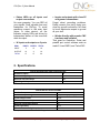
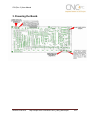
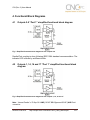
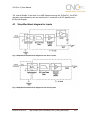
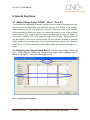
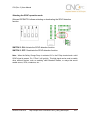
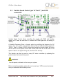
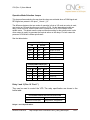
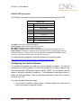
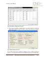
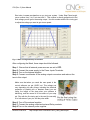
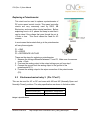
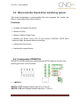
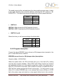
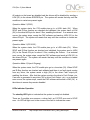
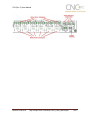
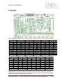
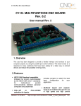
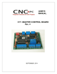
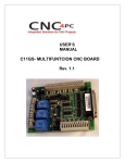
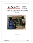
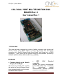
C32 (Rev. 3) User Manual C32- DUAL PORT MULTIFUNCTION CNC BOARD Rev. 3 User manual Rev. 1 1. Overview This card has been designed to provide a flexible connection with drivers and function boards using (RJ45 cables). It comes with sockets that allow direct connection of a Smooth Steeper Board (from Warp9 Tech Design Inc) or DB25 connectors. It also serves as an interface board for the pendants provided by CNC4PC (MPG2, MPG4, MPG12, MPG13, and MPG8). Features Connects directly to the Smooth Stepper (from Warp9). The board is provided with sockets that allow the Smooth Stepper Board to be plugged directly into this board. No ribbon cables required. Revision:3/28/2012 IEEE 1284 Standard compatible. Includes the circuitry recommended by the IEEE 1284 Level 1 standards for bidirectional parallel communications between personal computers and peripherals. http://cnc4pc.com/TechDocs/C32R3_User_Manual.pdf 1/27 C32 (Rev. 3) User Manual Built-in PWM-Based Speed Control. It has an isolated analog 0-10VDC output that will convert a PWM signal into an analog signal that can be used to command a commercial VFD. This analog can be adjusted using onboard potentiometer, so this board can be adjusted to other voltages. Built-in isolated DC-DC converter for analog output voltage. No need for using an external 12V power supply to power the analog output circuit. It now comes with a built-in DC-DC converter, so the power for the analog circuit is sourced from the +5vdc that power the board. Two Built-in Electromechanical Relays with NO and NC positions for spindle control. This board has two relays that can be used to control the direction (CW/CCW) and enable the drive (On/Off). RJ45 Connector for Easy VFD Connection. Monitors E-Stop, Safety Charge Pump, and Drivers (it only monitors G320/340, G203, G210/201, Dugong, and Viper Servomotor drives at this time). Enables drivers. and disables the An Electromechanical Relays with NO and NC positions for general use (Pin 2_16 or Pin 2_17, jumper selectable). Revision:3/28/2012 Microcontroller based SCHP. This board comes with a microcontroller that allows the implementation of a complex algorithm for sampling and analyzing the SCHP signal. RJ45 connectors for all I/Os. You only have to use standard networks cable to make all connections. Easy connections with CNC4PC relay boards and speed control boards. Connects 4 and 6 pendants (MPG2, MPG4, MPG8) axis and Optoisolated inputs. Works with regular parallel ports. Board C24 (from CNC4PC) or Ribbon cables can be used to connect regular parallel ports. All TTL 5VDC signals. Interface directly with parallel port interface products and other CNC4PC cards. 5VDC (TTL) cards are very common among automation devices. Buffered outputs. All outputs are buffered through the use of high speed and high current buffers, with the result that your devices receive all the power they need. http://cnc4pc.com/TechDocs/C32R3_User_Manual.pdf 2/27 C32 (Rev. 3) User Manual Status LEDs on all inputs and output connections. No more guessing. You can SEE all your signals. Save valuable time and brainpower for CNCing. To avoid remaining current to the main load (driver or other device), all the indicator outputs LEDs are driven by independent buffers of the ones that drive de output. 34 inputs and outputs on 2 ports. PINS PORT1 PORT2 TOTAL INPUT 5 13 18 OUTPUT 12 4 16 TOTAL 17 17 34 Inputs and outputs with close 5V and ground connections. Forget about grounding problems. Easily connect your pin by using your close by ground connection. No need to be an electronics expert to ground all your stuff. Works directly with popular CNC hardware and software. That goes for Geckdrive, Rutex and parallel port control software such as mach3, Linux EMC2, and TurboCNC. 2. Specifications. DIGITAL OPTOISOLATED INPUT SPECIFICATIONS Numbers of inputs 18 On-state voltage range 2 to 5V DC Maximum off-state voltaje 0.8V Typical signal delay 2.8uS DIGITAL OUTPUT SPECIFICATIONS Number of outputs 16 Maximum output voltage (5V power supply voltage) + 0.5V Typical output current 24mA Maximum off-state voltaje 0.44 V Maximum supported frequency 4M Typical signal delay 10 nS Time of transition to high impedance state 120mS* *Time passed since a fault in the SCHP signal is detected and the outputs are disabled. Revision:3/28/2012 http://cnc4pc.com/TechDocs/C32R3_User_Manual.pdf 3/27 C32 (Rev. 3) User Manual 3. Powering the Board. Revision:3/28/2012 http://cnc4pc.com/TechDocs/C32R3_User_Manual.pdf 4/27 C32 (Rev. 3) User Manual 4. Functional Block Diagrams 4.1 Outputs 2-9 “Port 1” simplified functional block diagram Fig. 1 Simplified functional block diagram for the outputs 2-9. Parallel Port coupling is done following IEEE 1284 standard recommendation. The indicator LED is driven by a different buffer. 4.2 Outputs 1, 14, 16 and 17 “Port 1” simplified functional block diagram Fig. 2 Simplified functional block diagram for the outputs 1, 14, 16 and 17. Note: “Internal Enable” = “E-Stop Pin” AND (“SCHP” OR “Bypassed SCHP”) AND Port 1 connection. Revision:3/28/2012 http://cnc4pc.com/TechDocs/C32R3_User_Manual.pdf 5/27 C32 (Rev. 3) User Manual The “Internal Enable” is the result of an AND Operation among the “E-Stop Pin”, the SCHP operation mode selected by the user and the port 1 connection to the PC parallel port or the Smooth Stepper. 4.3 Simplified block diagram for inputs Fig. 3 Simplified functional block diagram for the Port 1 inputs. Fig. 4 Simplified functional block diagram for the Port 2 inputs. Revision:3/28/2012 http://cnc4pc.com/TechDocs/C32R3_User_Manual.pdf 6/27 C32 (Rev. 3) User Manual 5. Special Functions 5.1 Safety Charge Pump “SCHP”. (Pin 17 “Port 2” ) This board takes advantage of Mach3’s ability to send a specific frequency through one of the pins of the parallel port when the program is in control of the system. CNC machinery can be very dangerous, and you could have a risk of the machine doing something different that what you intend the machine to do if the program loses control of your system. Mach be can be programmed in a way, so when it is “in control”, it delivers a 12.5 KHz signal through one of the pins. This card lets you use this signal to work as an On/Off switch for your system, enabling a powerful safety system for your equipment. If you ever had windows crash on you, then this card is for you. The port can also do weird things while the system is coming up, or down. For Configuring the Charge Pump in Mach X: Use the dialog Config / Ports and pins / Output Signals. Enable the Charge Pump output and configures it as is shown in the Fig. 12 Next, press the apply button. Fig. 5. Charge Pump configuration Revision:3/28/2012 http://cnc4pc.com/TechDocs/C32R3_User_Manual.pdf 7/27 C32 (Rev. 3) User Manual Selecting the SCHP operation mode Onboard DIPSWITCH allows activating or deactivating the SCHP detection function. SWITCH 2 ON: Activate the SCHP detection function. SWITCH 2 OFF: Deactivate the SCHP detection function. Note: When the Safety Charge Pump is activated, 5V in the E-Stop terminal and a valid SCHP signal is present, Pin 17 Port 2 will go high, This high signal can be used to enable other external devices, such as enabling other Breakout Boards, or relays that would enable servos, VFDs, contactors, etc…. Revision:3/28/2012 http://cnc4pc.com/TechDocs/C32R3_User_Manual.pdf 8/27 C32 (Rev. 3) User Manual 5.2 Variable Speed Control (pin 14 “Port 1” ) and VFD connection. Variable Speed Control allows controlling the spindle with PWM and direction signals, as if it was an axis motor. It converts the PWM signal into an analog (010VDC). A Variable Frequency Drive or Inverter works by modifying the frequency for AC motors. You can control most of these devices with an external analog signal (010VDC). That is, if there is 5VDC coming into through the control signal, the motor will run at 50% of full speed, if there was 10VDC, the motor will run at 100% of full speed. If there is no signal coming out, then the motor will stop. This function can also be used on many DC motor controllers by replacing the potentiometer that controls the speed. WARNING: You will require a voltmeter to fine tune your system. Before connecting anything, please be sure to read your VFD’s manual and make sure you understand all the safety issues. Revision:3/28/2012 http://cnc4pc.com/TechDocs/C32R3_User_Manual.pdf 9/27 C32 (Rev. 3) User Manual Operation Mode Selection Jumper This jumper allows selecting the way how the relays are activated when a PWM signal and REV signal are present in the pins 1_14 and 1_16. The difference between the two modes of operation is that on US mode one relay is used, one to start on CW and the other one to start on CCW. On the international mode one relay is used for on/off, and the other one to indicate the CW or CCW rotation of the spindle motor. This board uses the step and direction setting for the spindle motor under motor output in mach3 to generate the required action on the relays. For both cases the presence of PWM will indicate spindle start. See the tables below. US MODE (INT) PIN 1_14 PWM PWM 0 0 RELAYS 1_16 1 0 1 0 REL 1 OFF ON OFF OFF REL 2 ON OFF OFF OFF OPERATION Spindle ON CCW Spindle ON CW Spindle Off Spindle Off INTERNATIONAL MODE (INT) INPUTS 1_14 PWM PWM 0 0 1_16 1 0 1 0 RELAYS REL 1 ON ON OFF OFF REL 2 ON OFF OFF OFF OPERATION Spindle ON CCW Spindle ON CW Spindle Off Spindle Off Relay 1 and 2 (Pins 16 “Port 1”) They can be used to control the VFD. The relay specification are shown in the below table. ELECTROMECHANICAL RELAYS SPECIFICACTIONS Maximum Current (AC) 7A@240VAC; 10A@125VAC Maximum Current (DC) 15A@24VDC; 10A@28VDC Relays 1 and 2 Specifications. Revision:3/28/2012 http://cnc4pc.com/TechDocs/C32R3_User_Manual.pdf 10/27 C32 (Rev. 3) User Manual RJ45 for VFD Connection This RJ45 let you make an easy connection between this boars and the VFD. RJ45 PIN 1 2 3 4 5 6 7 8 RJ45 for VFD Function Analog. GND Analog Output Not Used REL 1 Normally Open Contact Ext. GND REL 2 Normally Open Contact Ext. 12VDC or 24VDC Relay Common An. GND: Ground of the Analog output signal Analog Output: Isolated Analog Output Signal (0-10V) Ext. GND: External 12V or 24V power supply GND. Ext. 12VDC or 24VDC: External 12VDC or 24VDC power supply used to enable the VFD. Relay Common: The signal or voltage wired to this terminal can be connected to the common terminals of the relay 1 and relay 2. Use the on-board RELAY COMMON JUMPERS to do this connection. Remove the jumper if this connection is not required. For additional wiring diagrams, check the bottom of the product’s page: http://www.cnc4pc.com/Store/osc/product_info.php?products_id=255 Configuring the Control Software: It is strongly recommend you read your control software’s manual. You need to configure your control software to control the spindle as if it was an angular axis. This card requires a PWM input signal to deliver 10VDC. So you have to set the speed of the motor (spindle) at maximum. For acceleration values adjust them to where you feel comfortable. Keep in mind the acceleration of the motor must also be set in your VFD. For configuring Mach follow these steps: 1. Go to Config / Ports&Pins / Motor Outputs. Enable the spindle and select the port and pins you wired for step and direction. Revision:3/28/2012 http://cnc4pc.com/TechDocs/C32R3_User_Manual.pdf 11/27 C32 (Rev. 3) User Manual Fig. 2. Ports&Pins configuration screenshot 2. Go to Config / Ports&Pins / Spindle Setup. In the motor control box, check Use Spindle Motor Output and Step /Dir Motor. Under Pulley Ratios set the pulley ratios of the machine. Fig. 3. Spindle Setup screenshot Go to Config / Motor Tuning / Spindle. On Steps per unit put 1,000, set velocity to maximum. For Acceleration, choose the acceleration that you feel comfortable with. Revision:3/28/2012 http://cnc4pc.com/TechDocs/C32R3_User_Manual.pdf 12/27 C32 (Rev. 3) User Manual Start slow, increase acceleration as you test your system. Under Step Pulse length, use a number from 3 to 5, but start with 3. This number is directly proportional to the final voltage you will get in the analog output. Use this number and the fine tuning pot to adjust the voltage you want to get at max speed. Fig. 4. Motor Tuning and Setup screenshot. After configuring the Mach, these steps should be followed. Step 1. Ensure that all external power sources are set to OFF. Step 2. Connect the power supply to the Power Inputs Terminals. Step 4. Turn on the external supplies Step 5. Connect a multimeter in the analog outputs connectors and make a fine tune to this output: Make sure that when you reach the max speed in the control software you get 10VDC out. This voltage can vary depending on many things, including the electrical properties of parallel port or breakout board you are using, the length of the step pulse your software is delivering, and the normal hi or low status of your step pin. Play with the fine tuning pot in the card, the normally hi or low status of your pin, and the pulse width. Step 6. Turn off the external supplies Step 7. Connect the analog output and external Relay contacts. Step 8.Turn on the external power supplies. Revision:3/28/2012 http://cnc4pc.com/TechDocs/C32R3_User_Manual.pdf 13/27 C32 (Rev. 3) User Manual Replacing a Potentiometer: This circuit can be used to replace a potentiometer of DC motor speed control circuits. This speed controller circuits are very commonly used by SIEG, KB Electronics, and many other oriental machines. Before explaining how to do it, please first keep in mind that it can be done if the voltage that goes though the pot is +12vdc or less. This circuit cannot be used for AC currents. In most cases the terminals that go to the potentiometer will carry these signals: P1 = GND P2 = WIPER P3 = REFERENCE VOLTAGE These are the steps for replacing a potentiometer: 1. Measure the voltage difference between P1 and P3. Make sure it measures under +12vdc. 2. Fine tune the analog output to the output voltage you got from step 1. 3. Connect the ground from the analog output to the ground of the potentiometer (P1). 4. Connect the analog output to the wiper connection of the potentiometer (P2). 5.3 Electromechanical relay 3. (Pin 1 Port 1) This can be used for AC or DC and come with NO and NC (Normally Open and Normally Closed) positions. The relay specification are shown in the below table. ELECTROMECHANICAL RELAY SPECIFICACTIONS Maximun Current (AC) 7A@240VAC; 10A@125VAC Maximun Current (DC) 15A@24VDC; 10A@28VDC Relays 3 Specifications. Revision:3/28/2012 http://cnc4pc.com/TechDocs/C32R3_User_Manual.pdf 14/27 C32 (Rev. 3) User Manual 5.4 Microcontroller based driver monitoring system. This board incorporates a microcontroller that runs programs that monitor the drivers, e-stop and perform other functions. Functions: Enables and disables the drivers. Monitors E-Stop. Monitors Safety Charge Pump. Monitors the Drivers errors pins. (it only monitors G320/340, DG2S Servo driver and Viper Servomotor drives at this time). Indicates the fault source. Indicates the system Status. 5.4.1 Configuration DIPSWITCH DIPSWITCH allows activating or deactivating the SCHP detection function, and selecting the driver to be monitored. SWITCH 1 SWITCH 1 OFF: Delayed enable output (Pin 17-Port 2). SWITCH 1 ON: Non Delayed enable output (Pin 17-Port 2). Revision:3/28/2012 http://cnc4pc.com/TechDocs/C32R3_User_Manual.pdf 15/27 C32 (Rev. 3) User Manual The enable output will be activated when the driver enable process starts. A delay in the signal activation time could be added by selecting the OFF position in the DIPSWITCH 1. The table below shows the delay time for every supported driver. DRIVER DELAY (Sec.) G320/340 5 G203 2 G210/201/Keling 2 Viper Servodriver 5 SWITCH 2 SWITCH 2 ON: Activate the SCHP detection function SWITCH 2 OFF: Deactivate the SCHP detection function SWITCH 3 and 4 Select the driver you will use according to the below table. DRIVER G320/G340 G203 G210/201/Keling Viper /Dugong DIP 3 DIP 4 0 0 1 0 0 1 1 1 5.4.2 Program description Connect the driver ERR/RES (servo drivers) or EN (stepper driver) terminal to the pin 5 of each RJ45 driver connector. ERR/RES (servo drivers) or EN (stepper driver) descriptions Operation Mode 1 (G320/G340) When the system starts, the C32 error/reset pins go to a low state (0V), making sure the driver remains disabled. When SCHP and E-Stop function are checked and validated and there is no fault signal coming from a driver, the system send a high (5V) to the driver’s error/reset pins for about 5 seconds to enable the drivers. After that the system monitors the driver’s err/res pins. If a fault occurs on any driver (0V in driver ERR/RES pin) or an external fault occurs (E-Stop or SCHP fault), the system stops and sends an e-stop signal (Active low) to the controller. Revision:3/28/2012 http://cnc4pc.com/TechDocs/C32R3_User_Manual.pdf 16/27 C32 (Rev. 3) User Manual All outputs on the board are disabled and the drivers will be disabled by sending a LOW (0V) to the drivers ERR/RES pin. The system will remain that way until the conditions to restart are present again. Operation Mode 2 (G203). When the system starts, the C32 enable pins go to a HIGH state (5V). When SCHP and E-Stop function are checked and validated, the system send a LOW (0V) to the driver’s EN pin for about 2 Sec, enabling the drivers. If an external error occurs, the system stops, resets the CNC software and sends a HIGH (5V) to the drivers EN pin. The system will remain that way until the conditions to restart are present again. Operation Mode 3 (G210/201). When the system starts, the C32 enable pins go to a LOW state (0V). When SCHP and E-Stop function are checked and validated, the system send a HIGH (5V) to the Drivers EN pin for about 2 Sec, enabling the Drivers. If an external error occurs, the system stops, resets the CNC software and sends a LOW (0V) to the drivers EN pin. The system will remain that way until the conditions to restart are present again. Operation Mode 4 (Viper & Dugong). When the system starts, the C32 enable pins go to a low state (0V). When SCHP and E-Stop function are checked and validated and there is no fault signal coming from any driver, the system sends a high (5V) to the driver Fault output pin, enabling the drivers. After that the system monitors the driver’s Fault Output pin. If an error is generated in any driver (0V in driver Fault Output pin) or an external error occurs, the system stops, resets the CNC software and sends a LOW (0V) to the drivers to ensure they remain disabled. LEDs indicator Operation The standby LED lights to indicate that the system is ready but disabled. There are 3 possible error sources, a driver fault, an E-STOP error and a SCHP error. An LED will light next to the source of the fault to indicate the cause. Revision:3/28/2012 http://cnc4pc.com/TechDocs/C32R3_User_Manual.pdf 17/27 C32 (Rev. 3) User Manual Revision:3/28/2012 http://cnc4pc.com/TechDocs/C32R3_User_Manual.pdf 18/27 C32 (Rev. 3) User Manual 6. Pinouts Fig. 9. RJ45 Distribution RJ45_1 RJ45 PIN P.P. PIN 1 NC 2 1_2 3 NC 4 GND 5 Err/res X 6 1_3 7 NC 8 5V Supported connection G320/G340 G203 G210/G201 Viper Servomotor Dugong DC Servo Driver RJ45_7 RJ45 PIN P.P. PIN 1 GND_EXT 2 1_13 3 1_12 4 1_11 5 NC 6 NC 7 5V_EXT 8 2_16 Supported connection C16 RJ45_2 RJ45 PIN P.P. PIN 1 NC 2 1_4 3 NC 4 GND 5 Err/res Y 6 1_5 7 NC 8 5V Supported connection G320/G340 G203 G210/G201 Viper Servomotor Dugong DC Servo Driver RJ45_3 RJ45 PIN P.P. PIN 1 NC 2 1_6 3 NC 4 GND 5 Err/res Z 6 1_7 7 NC 8 5V Supported connection G320/G340 G203 G210/G201 Viper Servomotor Dugong DC Servo Driver RJ45_8 RJ45 PIN P.P. PIN 1 GND_EXT 2 NC 3 NC 4 2_11 5 1_15 6 NC 7 5V_EXT 8 NC Supported connection C3 RJ45_4 RJ45 PIN P.P. PIN 1 NC 2 1_8 3 NC 4 GND 5 Err/res A 6 1_9 7 NC 8 5V Supported connection G320/G340 G203 G210/G201 Viper Servomotor Dugong DC Servo Driver RJ45_9 RJ45 PIN P.P. PIN 1 GND 2 2_17 3 2_16 4 2_1 5 2_14 6 NC 7 5V 8 NC Supported connection C19, C15, C5, C8 or C9 RJ45_5 RJ45 PIN P.P. PIN 1 NC 2 1_1 3 NC 4 GND 5 Err/res 5 6 1_14 7 NC 8 5V Supported connection G320/G340 G203 G210/G201 Viper Servomotor Dugong DC Servo Driver RJ45_10 RJ45 PIN P.P. PIN 1 GND 2 NC 3 NC 4 2_16 5 2_17 6 NC 7 5V 8 NC Supported connection C15, C8 or C9 RJ45_6 RJ45 PIN P.P. PIN 1 NC 2 1_16 3 NC 4 GND 5 Err/res 6 6 1_17 7 NC 8 5V Supported connection G320/G340 G203 G210/G201 Viper Servomotor Dugong DC Servo Driver RJ45_11 RJ45 PIN P.P. PIN 1 GND_EXT 2 2_15 3 2_13 4 2_12 5 2_10 6 NC 7 5V_EXT 8 NC Supported connection General Use *NC: Not Connected M_N: Parallel port or Smooth Stepper pin, where M is the port number and N is the pin number. * When connecting optoisolated boards, a connection between the ground of the C32 and the board must be used. This is the case for the C15 and C19 Revision:3/28/2012 http://cnc4pc.com/TechDocs/C32R3_User_Manual.pdf 19/27 C32 (Rev. 3) User Manual 7. Connecting a Pendant. Set the pendant enable jumper in ENABLE position if a pendant is connected to the DB25 connector. Pins 2_10, 2_11, 2_12, 2_13 and 2_15 are able to be used with the pendant (DB25 connector) or as general use input pin (RJ45 connector). Set the Pendant ON/OFF selection jumper in ON position if a pendant is connected to the DB25 connector. Otherwise set jumpers in OFF position. Fig. 9 Pendant ON/OFF selection jumper. Note: Pins (2_2 - 2_9) are configured as inputs and they are only accessible through the DB25 for Pendant. Revision:3/28/2012 http://cnc4pc.com/TechDocs/C32R3_User_Manual.pdf 20/27 C32 (Rev. 3) User Manual 8. Wiring diagrams While this board supports only TTL +5VDC signals, different kind of sensors, switches using different voltages can be connected using the diagrams that follow: Note: The below wiring diagrams are an example, any input can be used for the connections. Fig. 10 Wiring diagram to connect switches. Fig. 11 Wiring diagram to connect NPN open collector proximity sensors. For a 24V or 12V sensor, the recommended value for the external resistor R1 is 4.7K Ohm. Revision:3/28/2012 http://cnc4pc.com/TechDocs/C32R3_User_Manual.pdf 21/27 C32 (Rev. 3) User Manual Fig. 12 Wiring diagram to connect in parallel NPN open collector proximity sensors. Fig. 13 Wiring diagram to connect NPN proximity sensors with internal pull up resistor. Revision:3/28/2012 http://cnc4pc.com/TechDocs/C32R3_User_Manual.pdf 22/27 C32 (Rev. 3) User Manual Fig. 14 Wiring diagram to connect PNP open collector proximity sensors Connecting PNP open collector proximity sensor with the C32 Rev.3 Board C32 Rev. 3 R Value (12V) 470Ω R Value (24V) 1KΩ Table 15. R value to Connect PNP open collector proximity sensor with the C33. Fig. 16 Wiring diagram to do an “Auto Tool Zero” Revision:3/28/2012 http://cnc4pc.com/TechDocs/C32R3_User_Manual.pdf 23/27 C32 (Rev. 3) User Manual 9. Dimensions. All dimensions are in Millimeters. Disclaimer: Use caution. CNC machines could be dangerous machines. DUNCAN USA, LLC or Arturo Duncan are not liable for any accidents resulting from the improper use of these devices. The board is not fail-safe device, and it should not be used in life support systems or in other devices where its failure or possible erratic operation could cause property damage, bodily injury or loss of life. Revision:3/28/2012 http://cnc4pc.com/TechDocs/C32R3_User_Manual.pdf 24/27