1
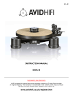
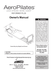
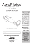
Poollift Neptune
with Transporter
Operating and Product Care Instructions
Doc.:065
Rev.: 0
Datum: 26/11/2012
Thank you for purchasing
equipment.
Nibotechncis
Your POOL LIFT is one of a series of quality
products designed especially for hospitals,
nursing homes and other health care
environments.
Please contact your local distributor if you
have any questions about the operation or
Nibotechnics
maintenance
of
your
equipment.
All references to ‘the resident’ in these instructions refer to the person being lifted,
and references to ‘the caregiver’ refer to the
person who operates the POOL LIFT.
References to left and right of the lift in these
instructions are as viewed when you are
standing at the rear of the POOL LIFT, facing
forward, (as viewed from the caregiver’s
pushing position).
Lifting operations in these instructions are
described as if lifting a resident from a chair.
The same operations can be performed effectively when lifting a resident from a wheelchair or sitting position on a stretcher,
although a second caregiver should support
the resident if the resident lacks sitting balance.
Operational Life
The operational life of the POOL LIFT and its
accessories e.g. stretcher, etc. is dependent
on the actual use conditions. Therefore,
before use, always make sure that the lift is
safe to use and has not been damaged (see
Preventive Maintenance Schedule at the end
of this document for details). If any damage
should be observed, do not use the POOL
LIFT.
Contents
SECTION
Safety Instructions
Product Description/Function
Parts referred to in this manual
POOL LIFT: maximum
capacities
POOL LIFT resident
transporters
Using Your POOL LIFT
Transferring to pool side with
chair
Transferring to pool side using
the stretcher
Attaching the chair or stretcher
to the POOL LIFT
Transfer to the pool
Transfer out of the pool
Product description/function
Parts referred to in this manual
Using your POOL LIFT
Transporter
Preparation of POOL LIFT
Transporter
Care of your POOL LIFT &
Transporter
Labels
Technical specifications
Preventive Maintenance
Schedule
Doc.: 065
Rev.: 0
3
Page
No.
4
5)6
5
6
6
7-10
7
7
7-8
9
9-10
11
11
12
13-14
15
16
17-23
24-27
Datum: 26/11/2012
Safety Instructions
• is dependent on caregiver who is present in
demanding situations
POOL LIFT can be used to lift a person, who:
READ BEFORE USE
Before using your POOL LIFT, familiarize
yourself with the various parts and controls as
illustrated in this document. Read this whole
manual thoroughly before operating your POOL
LIFT, in order to prevent injury or damage to the
product.
Definitions used in these instructions:
•
•
•
•
sits in a wheelchair
can partially bear weight on at least one leg
has some trunk stability
is dependent on caregiver in some
situations
POOL LIFT can be used to lift a person, who:
• Sits in a wheelchair
• no capacity to support herself
• is dependent on caregiver in most situations
POOL LIFT shall always be handled by a trained
caregiver who will care for the resident in
accordance with these Operating and Product
Care Instructions.
WARNING
Means: failure to follow these instructions
may result in injury to yourself or to others.
WARNING
CAUTION
Means: failure to follow these instructions
may cause damage to the product(s).
INTENDED USE
The POOL LIFT Neptune is a stationary lift that
has to be mounted in- or onto the Poolside
floor before resident transfer. It has been
designed to transfer
residents from the
poolside into the pool and the other way
around, using a chair or stretcher that has
been specially designed for the POOL LIFT.
The POOL LIFT has been designed to lift
a person, who:
A clinical assessment should be carried out
by a qualified nurse or therapist before lifting
residents for suitability of transfer in the
POOL LIFT e.g. residents who have
curvature of the spine or who are subject to
muscle spasms, or other residents, may
not be suitable.
During resident transfer to and from the
water, two caregivers are present. One to
operate the lifter and the other to assist the
resident at all times. Extra care should be
given during resident transfer from the water
when both resident and seat are wet.
GENERAL SAFETY INSTRUCTIONS
Only use Nibotechnics chairs, transporting
equipment and stretchers that have been
specifically designed for the POOL LIFT.
• is mobile, but may use a cane for support
• is independent, can clean & dress himself
• can tire quickly
POOLLIFT can be used to lift a person, who:
Do not overload the POOL LIFT beyond the approved lifting capacity (See page 6).
• uses a walking frame or similar
• can support herself to some degree
Do not manually lift the complete lifter but use
the transporter for all transfers.
WARNING
Insert the support column correctly
into the column location socket /base plate.
Doc.: 065
Rev.: 0
4
Datum: 26/11/2012
Product Description/Function
Parts referred to in this manual
1
2
3
16
5
4
15
6
14
7
11
8
9
12
13
10
Fig. 1
1. Mast
9.Footrest
2. Boom
10. Braked castors
3. Chair handle and hook up bar
11. Support column
4. Chair / Stretcher retaining catch
12. Column location socket
5. Fold back arm rest
13. Base plate
6. Sliding leg rest
14. Base cover
7. Left prong with chair catch
15. Rotation lock
8. Detachable sub-chassis
16. Winding handle
Doc.: 065
Rev.: 0
5
Datum: 26/11/2012
Product Description/Function
POOL LIFT: Maximum capacities
Toilet / Commode / Shower Chair
(TCS)
POOL LIFT (Socket or Base plate mounted):
The chair, which can be attached to / detached
from the POOL LIFT, has a removable subchassis. Only the chair is to go into the pool.
Leg rest available. Toileting facility (See Fig. 4).
• fitted with standard boom:
- 680 mm - 160 kg (352 lbs)
• fitted with boom:
- 1000mm - 160 kg (352 lbs)
Hook up
point
‘Fold back’ arms
• fitted with boom:
- 1200mm - 127 kg (280 lbs)
Detachable
commode
attachment
The capacities may differ, depending on the
type of boom. Inform yourself on the correct
capacity by reading the label fixed to the main
column housing, below the winding handle.
POOL LIFT Resident Transporters:
Footrest
The operation of the resident transporter units
may differ, depending on the type selected.
Fig. 4
To help prevent the accidental release of the
chair, a retaining catch is fitted to the left hand
‘prong’ of the sub-chassis. When the chair is
pushed onto the chassis, the catch connects
with a slot in the chair frame tube (see Fig. 10).
Press the catch in to remove the chair.
Swimchair
‘Fold back’ arms
Braked castors
Hook up
point
Stretcher Unit
The stretcher can be detached from the POOL
LIFT, but only the resident platform is intended
to go into the pool (See Fig.5).
Braked
castors
Footrest
Fig. 2
Adjustable
backrest
Hook up
point
Resident platform
Detachable from the POOL LIFT, but the whole
unit is lowered into the pool.
This unit may be detached from the POOL LIFT
once in the water and lowered securely onto
the pool floor, providing that the water depth is
correct for the resident (See Fig. 3).
Stretcher
trolley
Braked castors
Fig. 5
WARNING
Avoid any part of the resident’s or caregivers body coming between parts of the
lifter that join together or touch during
operation e.g. when attaching seat or
stretcher to mast etc.
Fig. 3
Doc.: 065
Rev.: 0
6
Datum: 26/11/2012
Using your POOL LIFT Neptune
Transferring to Poolside with chair
WARNING
The chair arms fold back for easy resident
access. Once the resident is suitably dressed
for swimming, transfer him/her into the chair
(swimchair or TCS).
To lower the stretcher, hold the backrest
and lift it slightly, then lift up the ratchet
position plate by holding either of the
ratchet plate knobs ONLY (See inset to fig.
10).
WARNING
If the resident is unstable or restless, the
safety rail may be used to protect the
resident on the stretcher.
Always ensure the brakes are on during
transfer onto and of the chair.
Attaching the chair or stretcher to
the POOL LIFT
Ensure the arm rests are folded forward,
encircling the resident for safety during
transfer.
Rotate the POOL LIFT away from the pool.
Never leave the resident unattended.
Turn the rotation lock anti-clockwise to rotate
(turn clockwise to lock) (See Fig. 7).
Always work according to good bathing
principles e.g. check water temperature,
water depth, care of the resident, etc.
Fig. 7
Fig. 6
The TCS chair may be used over a toilet if
necessary, when going to or from the
poolside. Use the brakes when over a toilet
(See Fig. 6).
WARNING
Make sure that the rotation lock is on
desired position.
Transferring to Poolside using the
Stretcher
The resident may be taken to the pool from
bedside or from another stretcher by using
the stretcher/trolley unit.
Transfer the resident by sliding or rolling as
appropriate.
To adjust the backrest when the resident is
on the stretcher, firstly support the resident
clear of the backrest, then carry out the
adjustment. (A second person may be
required for this operation). To make the
back more upright, simply lift up to the
Doc.: 065
Rev.: 0
7
Datum: 26/11/2012
Using your POOL LIFT Neptune
before attaching the chair or stretcher.
Reverse the chair unit or bring the
stretcher, sideways on, towards the POOL
LIFT mast until the top of the support frame
comes into the close proximity of the mast.
WARNING
Adjust the height of the mast so that
the hook up bar (with retaining catch) can
be positioned under the top of the
chair or stretcher support frame. The top
of the support frame must be firmly
attached to the hook up bar and the
retaining catch must have operated to
hold the frame tube (See Fig. 8).
Doc.: 065
Rev.: 0
8
Datum: 26/11/2012
Using your POOL LIFT Neptune
chair tube
Fig. 8
Raise the mast so that the chair wheels are
clear of the ground.
If you have a TCS chair, remove the subchassis. To help this action, take the resident’s feet off the foot rest by using the leg
rest if desired. Operate the catch, situated
under the left side of the seat, and gently
move the sub-chassis backwards until free
(See Fig. 9).
Sub-chassis fork (LH)
Fig. 9
To move the stretcher away from its trolley
after hook up to the POOL LIFT, lift the lever
situated at the foot end of the trolley. Check
if the mast catch works, then raise the POOL
LIFT mast (See Fig. 10).
Guide tube
Release lever
to separate
stretcher from
trolley
Doc.: 065
Guide tube
Ratchet
plate knobs
Rev.: 0
9
Resident back support
adjustment
Fig. 10
Datum: 26/11/2012
Using your POOL LIFT Neptune
Transfer to the pool
After the resident has been received by the
helper in the pool, remove the mast from the
water or return to repeat the procedure for the
next resident.
Release the POOL LIFT rotation lock (See Fig.
1) by turning anti-clockwise.
WARNING
Raise the resident sufficiently to clear the
pool edge (raised edge poolsides only) (See
Fig. 11).
There should always be someone at the
poolside competent to operate the POOL
LIFT while the resident(s) is in the water.
Fig. 11
Transfer out of the pool
WARNING
Fold back the chair arms, then lower the
chair or stretcher into the pool to the same
depth as before. The helper should put the
resident in the chair or stretcher and fold
the encircling arm rests on the chair back
around the resident or if using the
stretcher, put the safety rails around the
resident if required.
If using the Swimchair and it has been
removed from the POOL LIFT mast in the
pool, ensure it is correctly connected to
the mast and that the chair retaining catch
has operated before returning the resident
to the chair.
For sunken pools, raise the resident so that
the chair or stretcher sufficiently clears any
obstruction.
WARNING
Avoid any part of the resident’s or
caregiver’s body coming between parts of
the lifter that join together or touch during
operation e.g. when attaching seat or
stretcher to mast etc.
Ensure there is someone in the pool ready
to help the resident into the water.
Move the resident over the pool by pushing
sideways on the boom, until the desired
position is reached.
When resident and helper are ready, raise the
resident from the pool until high enough to
clear the poolside.
WARNING
Engage the rotation lock firmly.
Lower the resident until deep enough in the
water, indicated by the helper in the pool
(usually mid-chest).
If the resident is on a stretcher with the
shoulders raised, the water should come to
shoulder level to improve buoyancies.
Fold back the chair arm rest(s) to get
resident access, if required.
Fig. 12
Doc.: 065
Rev.: 0
10
Datum: 26/11/2012
Using your POOL LIFT Neptune
Release the rotation lock and rotate
back over the pool side by pulling the boom
towards you. When in position for transfer,
engage the rotation lock.
If you need to use the TCS chair, raise the
seat sufficiently high enough above the floor
and insert the prongs of the sub-chassis unit
into the chair frame tubes (see Fig. 9) until the
retaining catch works and locks.
Begin to lower the mast and at the same time
open the chair retaining catch on the mast,
just before the wheels of the sub-chassis
contact the floor. Continue to lower the mast,
keeping the chair retaining catch open, until
the chair frame tube is clear of the hook up
point. Push the chair away from the POOL
LIFT, apply the brakes and prepare the
resident for return to the changing room.
When using the stretcher, position the
stretcher trolley so that the stretcher can be
lowered directly onto it, ensuring that the
guide tubes on the stretcher trolley are in the
position as shown in Fig. 10. Continue
lowering, having opened the chair / stretcher
retaining catch, until the stretcher connects
with the locking catch on the trolley. Continue
lowering until the hook up point is completely
clear of the stretcher hook up tube.
WARNING
Ensure the brakes are applied whenever the
trolley is not being moved.
To unhook the stretcher unit from the mast,
push in the retaining catch lever on the mast
and continue to lower the mast until the
stretcher is clear of the hook up point.
Release the trolley brakes and return to the
changing room.
Doc.: 065
Rev.: 0
11
Datum: 26/11/2012
Product Description/Function Transporter
Parts referred to in this manual
1
2
4
3
7
5
6
8
9
1. Winding handle
4. Guide roller
7. Clamps
2. Mast
5. Guide
8. Brake
3. Triangular steady
6. Brake
9. Chassis
11
Fig. 13
Using your POOL LIFT Transporter
When this distance has been measured and
referring to Fig. 14, continue to fit the
triangular steady into the chassis. First,
position one of the location pegs into its hole
(See Fig. 16)
Fig. 16
Then carefully pull back the frame by
applying slight pressure, just enough to allow
the other peg to clear the chassis leg and
insert into its hole (See Fig. 17).
Fig. 14
Before using your Nibotechnics POOL
LIFT Transporter, it will have to be
assembled as follows:
Remove the three major components (See
Fig. 13) from their packaging. Remove and
hold the screw from the lower end of the mast
using the key provided. Carefully
slide the mast into the chassis centre socket
(See Fig. 14).
It can only go in one way.
Insert the screw through the chassis socket
and tighten into the mast using the key (See
Fig. 15).
Fig. 17
The steady should move freely and the
plastic covered stops will allow it to rest on
the chassis in the operational position (See
Fig. 18).
The fitting position of the triangular steady
depends on the POOL LIFT boom length.
Before continuing with your assembly,
determine which boom length is fitted by
measuring the distance referred to in Fig. 17.
Also read the preparation of the POOL LIFT
Transporter on pages 14-15.
Fig. 18
Your POOL LIFT Transporter is now ready for
use.
Fig. 15
12
Using your POOL LIFT Transporter
Preparation of POOL LIFT
Transporter
The triangular steady (See Fig. 13) of the
Transporter can be fitted in three separate
positions.
Each position is intended for the different
boom lengths that can be supplied with the
Nibotechnics POOL LIFT. Before attempting
to use the Transporter, ensure the steady is
fitted in the correct position on the Transporter, relative to the boom length of the POOL
LIFT to be lifted (See Fig. 19).
Fig. 20
Remove the chair or stretcher from the POOL
LIFT and move the boom (1) in Figs. 21 and
22 away from the pool edge, (See Fig. 21),
lower the mast (2) to within 150mm (6”) of the
ground level.
If after referring to Fig. 19 and measuring the
POOL LIFT boom, the triangular steady is
found not to be in the correct position, it can
be easily repositioned as follows:
Temporarily pull back one of the steady side
members (See Fig. 20) to pull out the pivot
peg from its hole. Pull out the other frame peg
and take the ‘steady’ away from the chassis.
Reposition the frame referring to Fig. 19,
reversing the above procedure.
680 mm (263/4)
Standard Boom
Triangular Steady
Position ‘A’
1000 mm (395/8)
Boom
Position ‘B’
1200 mm (471/4)
Boom
Position ‘C’
Fig. 19
13
Using your POOL LIFT Transporter
Position the clamp section of the Transporter
at its lowest position by turning the winding
handle (3) anti-clockwise.
POOL EDGE
Open the clamps (4) and approach the POOL
LIFT as shown in Fig. 21.
8
4
Engage the guide (5) with the POOL LIFT
column (6).
5
Lift the triangular steady (7) and rotate the
POOL LIFT boom (1) until it is in line with the
guide roller (8) on the steady.
3
7
Lower the steady until the roller engages in
the slot in the mast.
Lock the Transporter brakes (9) and secure
the clamps (4) so they firmly grip the POOL
LIFT column (but are not overtight).
1
Fig. 21
Tighten the POOL LIFT swivel clamp (10).
Operate the winding handle (3) in a clockwise
direction to raise the POOL LIFT from its
socket.
If the POOL LIFT is tightly held in the socket,
a slight rocking action should free it enough
to be lifted out.
1
When the column is clear of ground level,
release the Transporter brakes and move the
Transporter, with the POOL LIFT securely
attached, carefully away.
10
8
3
7
To re-install the POOL LIFT, reverse the
above procedure.
6
CAUTION
5
2
Do not operate the winding handle (3) while
the POOL LIFT is held in the Transporter.
Chairs / stretchers must not be attached to
the POOL LIFT while mounted on the
Transporter.
9
4
Fig. 22
14
Care of your POOL LIFT & TRANSPORTER
For cleaning your POOL LIFT, wipe down
with a damp cloth using warm water to which
a mild detergent has been added.
Environmental advice
When disposing of any items associated with
the lifter, contact the appropriate local
authority for advice.
For information on the maintenance
instructions of your POOL LIFT and
TRANSPORTER, direct yourself to the
Preventive Maintenance Schedule in the
back of this manual.
CAUTION
Do not use petroleum based solvents or
similar, as these may damage plastic parts.
WARNING
If in any doubt about the correct functioning
of the POOL LIFT, withdraw it from use and
contact the distributor.
UK LIFTERS ONLY: Important legislation
came into force on 5th December 1998,
which has an impact on the schedule of
service for your patient lifter(s), variable
height baths and other raising and lowering
equipment. The Lifting Operations and Lifting
Equipment Regulations (LOLER) 1998 and
The Provision and Use of Work Equipment
Regulations (PUWER 98) must be satisfied by
the duty holder. A scheme of six monthly
through examinations has been devised to
comply with the law and details can be
obtained from the distributor UK.
Spare parts, if required are available from
Nibotechnics or their approved distributors.
Special tools are required for certain
component replacement.
The simplest; safest and most effective way
to maintain your product in good working
order, is to have it methodically and
professionally serviced by the distributor
approved engineer using Nibotechnics
approved spare parts.
For information on service and maintenance
contracts,
please contact
your local
distributor.
15
Labels
1
2
3
Fig. 23
1+2. Attention: Read Operating Instructions
3. Safe Working Load: Dependent on Boom size / Serial Number
16
Technical Specifications
Component Weights
Kg
Lbs
POOL LIFT
Minimum weight (average).....................................................................70
Maximum weight (average)....................................................................85
154,32
187,39
Maximum Lifting Capacities
Basic lift with a boom of 680 mm...........................................................160
Basic lift with a boom of 1000 mm.........................................................160
Basic lift with a boom of1200 mm .........................................................127
Depth of
Socket
below floor
300
795
1310
305
POOL LIFT STANDARD COLUMN
17
352,74
352,74
279,99
Technical Specifications
COMMODE CHAIR & SUB-CHASSIS
500 mm
Seat width 360 mm
1040 mm
495 mm
820 mm
450 mm
This is available in:
AA1070
Chassis 450 with footrest
AA1071
Chassis 475 with footrest
AA1072
Chassis 500 with footrest
AA1073
Chassis 525 with footrest
AA1075
Chassis 450 with footbar
AA1077
Chassis 450 footbar + S/S Stems
AA1078
Chassis 450mm ft/rest + S/S Spin-
450 mm
145 mm
750 mm
495 mm
18
Technical Specifications
SWIMCHAIR
415 mm
400 mm
POOL LIFT TRANSPORTER
Standard mast
1722 mm
200 mm
Approx.
above
floor
680 mm
1200 mm
19
Technical Specifications
UPPER VIEW
POOL LIFT WITH STRETCHER UNIT
Stretcher
POOL LIFT
Head
end
Stretcher
Stretcher swing rads.
std boom = 190 cm
1 metre boom = 222 cm
1.2 metre boom = 242 cm
POOL LIFT WITH CHAIR UNIT, WITH AND WITHOUT LEG REST
POOL LIFT
CHAIR
Chair swing rads.
std boom = 150 cm
1 metre boom = 182 cm
1.2 metre boom = 202 cm
20
Chair and leg rest swing rads.
std boom = 200 cm
1 metre boom = 232 cm
1.2 metre boom = 252 cm
Technical Specifications
POOL LIFT POSITION A
SOCKET MOUNTING
800 mm REF
1000 mm REF
floor covering
screed
Mounting socket
Epoxy. Resin
grout
Reinforced concrete
Grade 35n/MM2 (5000 IB/IN2)
Check for services & ducts in locality of proposed foundations
Dimension ‘A’ 50 mm minimum recommended clearance between handrail & mast. If handrail not
provided, 50 mm clearance applies from extreme edge of pool to mast or any other obstruction.
Dimension ‘B’ 350 mm minimum distance from edge of wall to centre line of column applies only
when height of wall is maximum of 1000 mm
Dimension ‘C’ 250 mm minimum when screed is at 75 mm max for a minimum radius of 600 mm
in all directions.
Hole size for mounting socket, diameter 1.30 mm, depth 285 mm
21
Technical Specifications
GENERAL MEASUREMENTS
Raised pools and
therapy tanks
Boom position A
Deck level pools
Boom position B
Minimum roof height
Minimum roof height
2810 mm
(110.5 in)
2340 mm
(92 in)
800mm
(31.5 in)
800 mm
(31.5 in)
1100 mm
(43.5 in)
1270 mm
(50 in)
Stroke
Mast length
1735 mm
(68.3 in)
615
1075
680
1100mm
43.5 in
Floor level
290 mm
(11.4 in)
1140
1270 mm
(50 in)
Stroke
590
Floor level
130
1900
swing radius
1900
swing radius
Space requirements
with standard boom (800 mm)
Alternative boom length
Radius of swing with chair unit
1500 mm (59 in)
Radius of swing with stretcher
1900 mm (75 in)
Radius of swing with chair and leg rest 2000 mm (79 in)
1 metre (add 320 mm (12”) to swing radius)
1.2 metres (add 520 mm (21”) to swing radius
Difference between underside of stretcher and end of mast
22
Technical Specifications
POOL LIFT STRETCHER
1550 fully in position
+100
To disengagement
stretcher from trolley
2000 fully extended
600
1175
1075
Pick up
685
1065
930
740
640-620
325
RUN OFF
940
375
125 mm wheels
STRETCHER TROLLEY - OVERALL DIMENSIONS
520 mm
378 mm
990 mm
744 mm
1405 mm
23
Preventive Maintenance Schedule
The POOL LIFT is subject to wear and tear, and the following actions must be performed when specified to
ensure that the product remains within its original manufacturing specification.
WARNING
The points on this checklist are the minimum the manufacturer recommends. In some cases due to heavy
use of the product and exposure to agressive environment, more frequent inspections shall be carried out.
Continuing to use this product without conducting regular inspections or when a fault is found will seriously
compromise the user and residents’ safety. Local regulations and standards may be higher than the
manufacturers. Preventive maintenance specified in this manual can prevent accidents.
The parts which are entitled ‘Checks to be performed by Qualified distributor personnel’ have to be carried
out by qualified personnel, using correct tools and knowledge of procedures. Failure to meet these
requirements could result in personal injuries and / or unsafe product.
Preventive Maintenance Schedule
Before
each use
Action/Check
Every day
Every
Week
Every
Every
6 months 12 months
Nibotechnics Toilet / Commode / Shower chair
Visually inspect the sub-chassis to make sure the castors and footrest are securely attached before use
X
Examine all exposed parts, especially where there is
personal contact with the patient’s body. Make sure no
cracks or sharp edges have developed that could
cause patient or user injury or have become
unhygienic. Replace where necessary.
X
Make sure all external fittings are secure, and all
screws and nuts are tight.
X
Check that the swimchair / TCS sub-chassis / stretcher unit can be propelled in a normal manner, making
sure that the castors are quite free in their movement
Carry out decontamination of the Sub- chassis, Seat
and Frame in accordance with the Operating
Instructions and local regulations.
X
Make sure all instruction labels are firmly attached and
are readable. See Operating Instruction for location of
labels.
X
Make sure all 4 off castors rotate freely, are securely
fitted into the frame and the brakes lock. Also check
the castor tread for damage.
X
Make sure the safety catch, locking the seat frame to
the sub-chassis operates freely.
X
Make sure the seat and backrest are securely attached
to the frame.
X
CHECKS
TO BE PERFORMED BY
QUALIFIED
Carry out the Weekly Preventive Maintenance
Schedule checks plus the following:
Check the torque value on the castor inserts 12 Nm
(8.8 lbf ft)
Nibotechnics trained
PERSONNEL
X
Carry out a full inspection of the chair, checking
welded areas for cracks, corrosion and the general
condition of the chair. Replace those components
where required.
X
24
Every
2 years
Preventive Maintenance Schedule
Nibotechnics Swimchair
Visually inspect the chassis to make sure the castors
and footrest are securely attached before use.
X
Examine all exposed parts, especially where there is
personal contact with the patient’s body. Make sure
no cracks or sharp edges have developed that could
cause patient or user injury or have become
unhygienic. Replace where necessary.
X
Carry out decontamination of the Nibotechnics
Swimchair in accordance with
Nibotechnics
Operating Instructions and local regulations.
X
Make sure all instruction labels are firmly attached and
are readable. See Operating Instruction for location of
labels.
X
Make sure all external fittings are secure, and all
screws and nuts are tight.
X
Make sure all 4 wheels rotate freely, are securely fitted
into the frame and the 2 off rear castor brakes lock.
X
CHECKS
TO BE PERFORMED BY
QUALIFIED
Nibotechnics trained
Carry out the Weekly Preventive Maintenance
Schedule checks.
PERSONNEL
X
Carry out a full inspection of the chair, checking
welded areas for cracks, corrosion and the general
condition of the chair. Replace those components
where required.
X
Nibotechnics Stretcher and Trolley
Make sure the mattress is securely attached to the
stretcher platform using the Velcro strips.
X
Make sure the stretcher is correctly positioned on the
trolley and locked in place
X
Make sure the adjustable backrest lock is fully engaged in the slot.
X
Carry out decontamination
Stretcher and Trolley.
of the Nibotechnics
X
Make sure all instruction labels are firmly attached and
are readable. See Operating Instruction for location of
labels.
X
Make sure all external fittings are secure, and all
screws and nuts are tight.
X
Make sure all 4 wheels rotate freely, are securely fitted
into the frame and the 2 off castor brakes lock.
X
Make sure the release lever, allowing separation of the
stretcher from the trolley, moves freely.
X
Where an additional guard-rail is used, make sure the
spring clip is attached to a chain and locates locking
the guard-rail in place satisfactorily. Replace if required.
X
Check the condition of the patient platform on the
stretcher frame, making sure it is not cracked, loose,
the Velcro is firmly attached etc. Replace as necessary.
X
CHECKS
TO BE PERFORMED BY
QUALIFIED Ni b ot ec h ni cs
Carry out the Weekly Preventive Maintenance Schedule checks.
t r ai ne d
PERSONNEL
X
Carry out a full inspection of the stretcher and trolley,
checking welded areas for cracks, corrosion and the
general condition of the stretcher and trolley. Replace
those components where required.
X
25
Preventive Maintenance Schedule
Nibotechnics POOL LIFT Transporter
Check the condition and bond of the clamp pads and
for free movement of the clamps.
X
Check for smooth operation of the lifting mechanism.
X
Make sure that castors are free in their movement and
that the brakes operate efficiently.
X
Make sure that all external fittings are secure and that
screws and nuts are tight.
X
Make sure that all safety labels are firmly attached and
in good condition. Replace as necessary. See Operating Instruction for location of labels.
X
CHECKS
TO BE PERFORMED BY
QUALIFIED
Nibotechnics trained
Carry out the Weekly Preventive Maintenance Schedule checks.
PERSONNEL
X
Carry out a general visual inspection of all external
parts to make sure no adverse damage/wear has occurred. Replace components where necessary.
X
Clean and re-grease winding shaft using Energrease
FG 00-EP or equivalent.
X
Clean and re-grease clamp-screws and hinge-pins using silicone grease or equivalent.
X
On the guide wheel frame make sure the guide wheel
rotates freely and lubricate using silicone grease or
equivalent as required.
X
Nibotechnics POOL LIFT
After use each day, wash the POOL LIFT and resident
transporters with fresh water (not pool water) and wipe
dry. If the POOL LIFT has not been used and is stored
in a pool side atmosphere, then periodically wash it
down with fresh water and wipe dry, as pool side atmospheres can be corrosive.
X
Make sure the chair / stretcher retaining safety catch
on the traveller operates correctly and that the spring
pressure within the catch is maintained.
X
Examine all exposed parts, especially where there is
personal contact with the patient’s body. Make sure
no cracks or sharp edges have developed that could
cause patient or user injury or have become
unhygienic. Replace where necessary.
X
Carry out decontamination of the Nibotechnics POOL
LIFT in accordance with Nibotechnics Operating
Instructions and local regulations.
X
With the seat in the fully lowered position,
visually examine the exposed lifting cable within the
mast for any signs of damage. If the lifting cable is
damaged in any way the POOL LIFT must not be
used until the lifting cable is replaced.
X
Make sure all external fittings are secure and all
screws and nuts are tight.
X
Fully raise and lower the seat and jib using the winding
handle to check for full and satisfactory movement.
X
Make sure all instruction labels are firmly attached and
are readable. Replace as required. See Operating
Instruction for location of labels.
X
Check the mast rotation lock to ensure that it locks
and releases satisfactorily
X
26
Preventive Maintenance Schedule
CHECKS
TO BE PERFORMED BY
QUALIFIED Nibotechnics trained PERSONNEL
Visually inspect the wire rope assembly for signs of
corrosion, fraying and wear etc by removing the cover
from the housing. Once removed, visually inspect the
rope whilst operating the winding handle to raise and
lower the hoist. Replace if necessary.
X
Carry out a general visual inspection of all external
parts and make sure that no adverse damage
has occurred during use.
X
Perform a Load Test to the Safe Working Load (SWL).
X
Carry out the 6 Monthly Preventive Maintenance
Schedule checks plus the following:
Replace all friction discs within the clutch assembly.
Reset the clutch assembly to support the following
Safe Working Load of: For 800 mm and 1 metre Boom
Safe Working Load =25 Stone/ 350 lbs/160 Kg
For 1.2 metre Boom
Safe Working Load =20 Stone/280 lbs/128 Kg
• Refer to nameplate for Safe Working Load.
X
If a base plate is mounted check for security of fixings.
Do a torque tightening check of the following:
Boom to housing, 4off bolts - 68Nm (50lb ft). See
Figure 1, Item Ax4.
Boom to mast, 4 off bolts - 54Nm (40lb ft). See Figure
1. Item Bx4.
X
Carry out the 12 Monthly Preventive Maintenance
Schedule checks plus the following:
Replace the wire rope and drum assembly regardless
of appearance.
Replace the pawl springs (2off) within the ratchet
assembly.
X
27