1
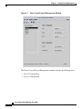
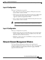
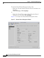
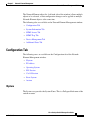
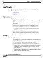
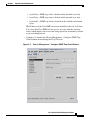
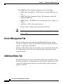
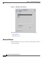
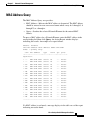
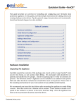
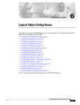
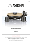
C H A P T E R
5
Network Element Management
This chapter describes how to manage chassis using the Cisco Catalyst Switch
Manager, and consists of the following primary sections:
•
Chassis Layer2/Layer3 Management Window
•
Network Element Management Window
•
MAC Address Query Window
Chassis Layer2/Layer3 Management Window
The Chassis Layer2/Layer3 Management window provides capabilities to enable
or disable Cisco discovery, unidirectional, LAN and IP routing protocols on the
network element.
To launch the Chassis Layer2/Layer3 Management window, either:
•
Right–click a Site object within the Network or Physical containment views,
then choose
CSM/7600 Manager > Chassis Mgmt–IP
Or
•
Right–click a Network Element object within the Network or Physical
containment views, then choose Chassis Mgmt–IP.
Figure 5-1 is an example of the Chassis Layer2/Layer3 Management window.
Cisco Catalyst Switch Manager User Guide
OL-6380-01
5-1
Chapter 5
Network Element Management
Chassis Layer2/Layer3 Management Window
Figure 5-1
Chassis Layer2/Layer3 Management Window
The Chassis Layer2/Layer3 Management window includes the following areas:
•
Layer 2 Configuration
•
Layer 3 Configuration
Cisco Catalyst Switch Manager User Guide
5-2
OL-6380-01
Chapter 5
Network Element Management
Network Element Management Window
Layer 2 Configuration
The Layer 2 Configuration area provides:
•
CDP—Displays the Cisco Discovery Protocol (CDP) global status on the
network element, enabled or disabled.
•
UDLP—Displays the UniDirectional Link Detection Protocol (UDLP) global
status on the network element: enabled, aggressive, or disabled. The
“aggressive” option is not applicable for CatOS.
•
802.1x—Displays the 802.1x Port Based Authentication global status on the
network element, enabled or disabled.
Note
Dot1x cannot be enabled if dynamic mode is enabled on one or more
ports.
Layer 3 Configuration
The Layer 3 Configuration area provides:
•
IP CEF—Displays the status of the IP CEF routing on the network element,
enabled or disabled. This feature cannot be disabled on Cisco 3950, 4000,
4500, 6000, 6500, and 7600 series devices.
•
IP Multicast—Displays the status of the IP Multicast routing on the network
element, enabled or disabled.
Network Element Management Window
The Network Element Management window provides monitoring and
management information for properties related to the . These properties include
the Telnet and Enable passwords, global performance logging, and SNMP
properties for the entire switch.
Cisco Catalyst Switch Manager User Guide
OL-6380-01
5-3
Chapter 5
Network Element Management
Network Element Management Window
To launch the Network Element Management window, either:
•
Right–click a Site object within the Network or Physical containment views,
then choose
CSM/7600 Manager > NE Config/Mgmt.
Or
•
Right–click a Network Element object within the Network or Physical
containment views, then choose NE Config/Mgmt.
Figure 5-2 is an example of the Network Element Management window.
Figure 5-2
Network Element Management Window
Cisco Catalyst Switch Manager User Guide
5-4
OL-6380-01
Chapter 5
Network Element Management
Network Element Management Window
The Network Element object list (left-hand side of the window) allows multiple
objects to be selected, so that configuration changes can be applied to multiple
Network Element objects at the same time.
The following tabs are available on the Network Element Management window:
•
Configuration Tab
•
System Information Tab
•
SNMP Access Tab
•
SNMP Trap Tab
•
Device Management Tab
•
Additional Notes Tab
Configuration Tab
The following areas are available on the Configuration tab of the Network
Element Management window:
•
ISystem
•
IP Address
•
Operating System
•
IOS Session
•
Cat OS Session
•
Reset System
•
Actions
ISystem
The System area provides the System Name. This is a Fully qualified name of the
switch or router.
Cisco Catalyst Switch Manager User Guide
OL-6380-01
5-5
Chapter 5
Network Element Management
Network Element Management Window
IP Address
The IP Address area provides:
•
Supervisor—IP address used to access the switch or router.
•
MSFC—IP address of the management agent on the MSFC daughter card
(only in Hybrid OS).
Operating System
The Operating System area provides:
•
Expected OS Type—This attribute is used by a client that initiates a
deployment context to indicate the type of operating system expected on a
managed device. This can only be changed when the device is
decommissioned. Values are:
– Catalyst OS Only
– Hybrid OS
– Native OS
•
Active OS Type—The operating system type detected on the managed device.
IOS Session
Note
The attributes within this area are inactive for Catalyst OS devices.
The IOS Session area provides:
•
Username—User name to establish an IOS management session with the
device over telnet.
•
Password—Password to establish an IOS management session with the
device over telnet.
•
EXEC Password—Password to enter privileged EXEC mode.
Cisco Catalyst Switch Manager User Guide
5-6
OL-6380-01
Chapter 5
Network Element Management
Network Element Management Window
Cat OS Session
The Cat OS Session area provides:
•
Same As IOS?—If enabled, the IOS telnet username and password are
automatically used to connect to the Supervisor module over CatOS in Hybrid
OS configurations.
If this attribute is set to ‘No’ the Username, Password, and EXEC Password
fields in the Cat OS Session area become active.
•
Username—User name to establish a CatOS management session with the
device over telnet.
•
Password—Password to establish a CatOS management session with the
device over telnet.
•
EXEC Password—Password to enter privileged EXEC mode in a CatOS
session.
If the above passwords are incorrect, some window values may report as ERROR.
The attributes within this area are inactive for IOS devices.
Reset System
The Reset System area provides:
•
Last Restart Reason—Text message displaying why the switch or router was
restarted.This has no value in a pure CatOS installation
•
Reset—Button used to reset the switch or router. This action power cycles the
switch or router.
You are prompted to confirm whether you really want to reset the switch or
router.Only users with administrative privileges can use the Reset button
Any changes to the running configuration are saved when you reset the switch
or router is reset using the Reset button.
Cisco Catalyst Switch Manager User Guide
OL-6380-01
Launch Internet
5-7
Chapter 5
Network Element Management
Network Element Management Window
Actions
The Actions area provides:
•
Commission— Commissions the object manually. You can commission the
object only if the object is in a decommissioned state. Clicking this button
forces a subchassis discovery to be executed, and propagates the
commissioned status to all subobjects.
•
Decommission—Decommissions the object manually and propagates the
decommissioned status to all subobjects. In the decommissioned state, the
properties of the object are not monitored. As a result, data displayed in the
configuration window may not be current.
System Information Tab
The System Information tab of the Network Element Management window
provides the following information:
•
System Up Time—Duration of time indicating how long the system has been
running. This attribute is read-only.
•
System Services—List of OSI layers supported by the switch or router. This
attribute is read-only.
•
System Location—Location of the switch or router.
•
System Contact—Name of the person who is the contact for this
switch/router.
•
System Description—Multiline text description of the switch/router. This
attribute is read-only.
•
Cisco Contact Information—Details on how to contact Cisco Systems. This
attribute is read-only and has no value in a pure CatOS installation.
Cisco Catalyst Switch Manager User Guide
5-8
OL-6380-01
Chapter 5
Network Element Management
Network Element Management Window
SNMP Access Tab
The following areas are available on the SNMP Access tab of the Network
Element Management window:
•
IOS/LINUX SNMP
•
Cat OS SNMP
IOS/LINUX SNMP
The IOS/LINUX SNMP area provides:
•
SNMP v2c Read Community—The v2c community string used to read data
from the agent.
•
SNMP v2c Write Community—The v2c community string used to write data
from the agent.
•
Last Authentication Failure Address—The IP address of the last host that
caused an SNMP authentication failure to occur. This has no value in a pure
CatOS installation.
The attributes within this area are inactive for Catalyst OS devices.
Cat OS SNMP
The Cat OS SNMP area provides:
•
Same As IOS?—If enabled, the IOS SNMP version and communities will be
used to access the SNMP Agent on the Supervisor module in Hybrid OS
configurations.
If this attribute is set to ‘No’ the SNMP Read Community and SNMP Write
Community fields in the Cat OS SNMP area become active.
•
SNMP v2c Read Community—The v2c community string used to read data
from the agent.
•
SNMP v2c Write Community—The v2c community string used to write data
to the agent.
The attributes within this area are inactive for Catalyst OS devices.
Cisco Catalyst Switch Manager User Guide
OL-6380-01
5-9
Chapter 5
Network Element Management
Network Element Management Window
SNMP Trap Tab
The following areas are available on the Configuration tab of the Network
Element Management window:
•
Trap Generation
•
SNMP Trap
Trap Generation
The Trap Generation area provides:
•
SNMP Trap Status—Indicates the level at which SNMP traps are enabled.
The level is one of these values:
– disabled
– layer2Only—SNMP traps are enabled on the datalink layer only.
– layer3Only—SNMP traps are enabled on the network layer only.
– layer2And3—SNMP traps are enabled on the datalink and network
layers.
•
Enable—Enables all SNMP trap generation from the switch or router.
•
Disable—Disables all SNMP trap generation from the switch or router.
SNMP Trap
The SNMP Trap area provides:
•
Trap Client IP Table—IP address table to which SNMP traps generated by the
switch or router are sent.
– Trap Client IP—IP address to which SNMP traps are sent.
– Client Community—Community string used within the SNMP trap.
– SNMP Version—Version of the SNMP protocol used by Cisco EMF to
communicate with the managed device. This field has the following
value: snmpv2c.
– Notification Layer - Indicates the level at which the SNMP trap client is
defined. The level is one of these values:
Cisco Catalyst Switch Manager User Guide
5-10
OL-6380-01
Chapter 5
Network Element Management
Network Element Management Window
•
layer2Only—SNMP trap client is defined on the datalink layer only.
•
layer3Only—SNMP trap client is defined on the network layer only.
•
layer2And3—SNMP trap client is defined on the datalink and network
layers.
The IP address of the Cisco EMF server host should be in this list at all times.
If it is not, then Cisco EMF will not receive any traps from the switch or
router, which might result in an event being reported in an untimely fashion
or an event being missed.
•
Configure—Launches the Chassis Management - Configure SNMP Trap
Client window for modifying the Trap Client list.
Figure 5-3
Chassis Management—Configure SNMP Trap Client Window
Cisco Catalyst Switch Manager User Guide
OL-6380-01
5-11
Chapter 5
Network Element Management
Network Element Management Window
The SNMP Trap Client Configure window provides the following:
– SNMP Trap Client Address—The IP address to which SNMP traps are
sent.
– SNMP Trap Client Community String—The community string used
within the SNMP trap.
– SNMP Version—The SNMP version running on the device, snmpv1c or
snmpv2.
– Add Client—Adds a client to the client list.
– Remove Client—Removes the client from the client list.
Note
An error is reported if a nonexistent client is removed or if an existing
client is added.
Device Management Tab
The Device Management tab of the Network Element Management window
consists of a single area, Write Config to Flash. The Write Config to Flash area
provides a single button, Write Mem
It changes to the running config are saved to the startup config. In the future, when
the startup config is accessed, it will contain the most recent running config
written to memory.
Additional Notes Tab
The Additional Notes tab of the Network Element Management window contains
the Notes area which is a text box that allows you to type in additional notes. For
example, this information can include text indicating why global performance
logging is turned on.
Cisco Catalyst Switch Manager User Guide
5-12
OL-6380-01
Chapter 5
Network Element Management
MAC Address Query Window
MAC Address Query Window
MAC Addresses are used within a network to identify specific ports on an
interface. Other devices in the network use MAC addresses to locate ports in order
to create and update routing tables and data structures. The MAC Address Query
window allows you to query a Network Element for a MAC address.
The query results of a Network Element based on a MAC address display in an
Action Report window, indicating data similar to a “show mac address table
address xxxx.xxxx.xxxx” command.
Note
MAC address queries may require extensive lengths of time to complete
depending on the inventory of the Network Element object being queried.
To launch the MAC Address Query window, either:
•
Right–click a Site object within the Network or Physical containment views,
then choose CSM/7600 Manager > NE MAC Address Query.
Or
•
Right–click a Network Element object within the Network or Physical
containment views, then choose NE MAC Address Query.
Figure 5-3 is an example of the MAC Address Query window.
Cisco Catalyst Switch Manager User Guide
OL-6380-01
5-13
Chapter 5
Network Element Management
MAC Address Query Window
Figure 5-4
MAC Address Query Window
The following areas are available on the MAC Address Query window:
•
Network Element
•
MAC Address Query
Network Element
The Network Element area consists of a listing of all network elements available
via the selected object.
Cisco Catalyst Switch Manager User Guide
5-14
OL-6380-01
Chapter 5
Network Element Management
MAC Address Query Window
MAC Address Query
The MAC Address Query area provides:
•
MAC Address—Indicates the MAC address to be queried. The MAC address
should be entered in xxxx.xxxx.xxxx format where x may be 1 through 9, A
through Z, or a through z.
•
Query—Searches the selected Network Element for the entered MAC
address.
To query a MAC address for a Network Element, enter the MAC address in the
corresponding field then click Query. An Action Report window displays
indicating the results. An example of a report follows.
Chassis: ems6513a
show mac-address-table address: 0006.524B.6A0A
Codes: *-primary entry
vlan
mac address
type
learn
qos
ports
-+-----+--------------+-------+------+----+------+
Supervisor:
* ---
006.524b.6a0a
static
No
---
Router
* ---
006.524b.6a0a
static
No
---
Router
* 613
006.524b.6a0a
static
No
---
Router
* 333
006.524b.6a0a
static
No
---
Router
* 652
006.524b.6a0a
static
No
---
Router
* 701
006.524b.6a0a
static
No
---
Router
* 700
006.524b.6a0a
static
No
---
Router
* 678
006.524b.6a0a
static
No
---
Router
* 677
006.524b.6a0a
static
No
---
Router
* 908
006.524b.6a0a
static
No
---
Router
* 904
006.524b.6a0a
static
No
---
Router
* 907
006.524b.6a0a
static
No
---
Router
* 906
006.524b.6a0a
static
No
---
Router
* 710
006.524b.6a0a
static
No
---
Router
* ---
006.524b.6a0a
static
No
---
Router
* 999
006.524b.6a0a
static
No
---
Router
* 201
006.524b.6a0a
static
No
---
Router
--------------------------------------------------
If a MAC address is not found, a message displays in the table area of the report
indicating no results found.
Cisco Catalyst Switch Manager User Guide
OL-6380-01
5-15
Chapter 5
Network Element Management
MAC Address Query Window
Cisco Catalyst Switch Manager User Guide
5-16
OL-6380-01