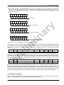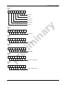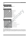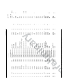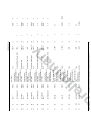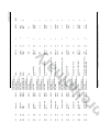
1
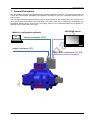
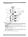
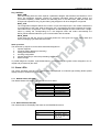
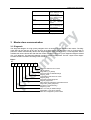
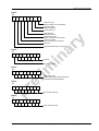
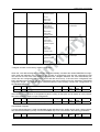
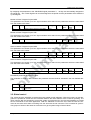
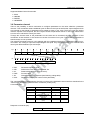
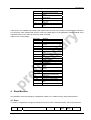
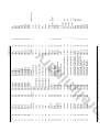
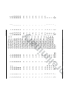
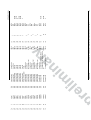
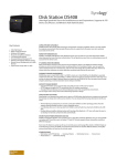
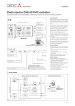
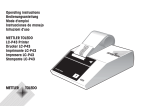
DIV PQ
DIGITAL INTERFACE VALVE
DIGITAL INTERFACE VALVE WITH PROFIBUS
INTERFACE
User Manual - Firmware DIV PQ
(B99225-DV010-BE400; Version 0.2, 10/07)
Copyright
Copyright
© 2007 Moog GmbH
Hanns-Klemm-Straße 28
71034 Böblingen
Deutschland
Completeness
This document is complete only when used in conjunction with
the product-related hardware and software documentation required for the relevant application, as for example operating instructions of the valve and other manuals.
Telephone:
Fax:
E-mail:
Internet:
Selection and qualification of personnel
As specified in the product-related hardware and software
documentation required for the relevant application, only users
properly qualified and authorized for these tasks may work with
and on our products.
+49 7031 622-0
+49 7031 622-191
[email protected]
http://www.moog.com/Industrial
All rights reserved.
No part of this document may be reproduced in any form (print,
photocopies, microfilm, or by any other means) or edited, duplicated, or distributed with electronic systems without our prior
written consent.
Offenders will be held liable for the payment of damages.
Subject to change without notice.
We reserve the right to make changes to this document at any
time and without specified reasons.
Note
This document has been prepared with great care in compliance with the relevant regulations, state-of-the-art technology
and our many years of knowledge and experience, and the contents have been generated to the best of the authors' knowledge. However, the possibility of error remains and improvements are possible.
Please feel free to submit any comments about possible errors
and incomplete information to us.
Table of Contents
1 General Description.................................................................................................................... 3
2 PROFIBUS state machine .......................................................................................................... 4
2.1 Status LEDs......................................................................................................................................5
2.1.1 Module Status LED (MS) ..................................................................................................5
2.1.2 Network Status LED (NS) .................................................................................................5
3 Master slave communication..................................................................................................... 6
3.1
3.2
3.3
3.4
3.5
3.6
Diagnosis ..........................................................................................................................................6
Changing station address...............................................................................................................12
Parameter telegram........................................................................................................................13
Configuration telegram ...................................................................................................................15
Global control .................................................................................................................................18
Parameter channel .........................................................................................................................19
4 Store/Restore ............................................................................................................................ 20
4.1 Store ...............................................................................................................................................20
4.2 Restore ...........................................................................................................................................21
5 PROFIBUS hardware and cabling ........................................................................................... 21
5.1
5.2
5.3
5.4
Complied hardware standards .......................................................................................................21
Cabling of PROFIBUS Slaves ........................................................................................................22
Advice according Baude rates........................................................................................................22
PROFIBUS connectors...................................................................................................................22
6 Object dictionary ...................................................................................................................... 23
7 Literature ................................................................................................................................... 40
Moog GmbH
User Manual - Firmware DIV PQ (B99225-DV010-BE400; Version 0.2, 10/07)
2
1 General Description
1 General Description
This specification describes the PROFIBUS DPV1 fieldbus interface for the DIV. The physical connectors as
well as the profile specific parameters and telegrams necessary to built up a connection between the PLC
and the valve.
The described functions and parameters are only a small extract from the existing ones. The complete functional specification is described in the PROFIBUS - DP Profile, Fluid Power Technology. Developed by the
PROFIBUS Working Group „Fluid Power Technology“ based on the profiles developed by the VDMA e.V.
Working Group „Fluid Power Technology“.
MoVaCo (configuration software)
PC
PROFIBUS master
service connector (X10)
supply connector (X1)
PROFIBUS connectors (X3, X4)
Moog GmbH
User Manual - Firmware DIV PQ (B99225-DV010-BE400; Version 0.2, 10/07)
3
2 PROFIBUS state machine
2 PROFIBUS state machine
Power Off
Power_On
Baud_Search
Power_On
WD_Time_Out
Baud_Control
WD_DP_Control_Time_Out
WD_On = 0
Set_Slave_Add
WD_On = 1
DP_CONTROL
WAIT_PRM
Slave_Diag
Get_Cfg
Set_Slave_Add
Set_Prm
Chk_Cfg, not ok
Set_Prm, not ok
WAIT_CFG
Slave_Diag
Get_Cfg
Set_Prm
Chk_Cfg, ok
DATA_EXCH
Slave_Diag
Get_Cfg
Set_Prm
Power_On
Baud_Search:
The valve is capable of detecting the PROFIBUS baudrate set by the master automatically. When
the electronic is in Baud_Search state it can not accept any message. The electronic is searching for
the transmission rate of the bus on different baudrates, trying to detect a correct SD1, SD2 or SD3
telegram. After identifying a baudrate the controller switches to Baud_Control state.
Baud_Control:
The detected baudrate is constantly monitored in the Baud_Control state. Each error free detected
telegram to its own station address resets the internal watchdog. The watchdog timer can be set by
the user via the parameter telegram.
TWD = (1 ms or 1 ms) * WD_FACT_1 * WD_FACT_2
(see byte 7 of the “Set_Prm” telegram)
If the watchdog expires the valve falls back to the Baud_Search state and starts searching the badrate again. A watchdog time between 2 ms and 650 s – independent of the baudrate – can be implemented by using the watchdog factors.
Only in Power_On state the slave accepts a Set_Slave_Address telegram.
Moog GmbH
User Manual - Firmware DIV PQ (B99225-DV010-BE400; Version 0.2, 10/07)
4
2 PROFIBUS state machine
DP_CONTROL:
WAIT_PRM:
After the startup phase the slave expects a parameter telegram which defines the behaviour of the
slave. The parameter telegram contains for example information about the ident number, the
sync/freeze capability, master address and watchdog time. In the state WAIT_PRM the slave also
accepts and responds to Get_Cfg and Slave_Diag telegrams. All other telegrams are ignored.
WAIT_CFG:
The configuration telegram defines the number of input and output bytes. The master transmits the
IO configuration to the valve. After receiving the Chc_Cfg telegram the valve compares the configuration with its own configuration. If the configuration is acknowledged the valve confirms the configuration by setting the corresponding bit in the diagnosis state and enters automatically the
DATA_EXCH state and starts the cyclic communication with the master.
DATA_EXCH :
If both Chk_Cfg and Set_Prm are confirmed positive the valve goes into DATA_EXCH state and
starts exchanging cyclic data with the master.
Start up routine
The ideal start up sequence for the before described telegrams is:
1.
2.
3.
4.
5.
6.
request diagnosis
changing station address (if necessary)
setting parameterization
checking configuration
request diagnosis (to check the preceeding commands)
data exchange
In parallel diagnosis requests, reparameterizations, reconfigurations and global control telegrams are accepted and processed by the valve.
2.1 Status LEDs
The valve’s operating mode and the network status are displayed on multicolor light emitting diodes (status
display LEDs) on the electronics housing.
2.1.1 Module Status LED (MS)
The Module Status LED displays operational and error states.
Module status LED (MS)
Off
Green
Blinking Green
Blinking red
red
Blinking red-green
Condition
No supply voltage
normal operation
Valve standby mode
Correctable error
unrecoverable error
Self-test
Table 1: Module Status (MS)
2.1.2 Network Status LED (NS)
The network status LED displays the status of the PROFIBUS network.
Network status LED (NS)
Off
Green
Moog GmbH
Condition
No supply voltage
state: “DATA_ EXCH“
valve is in data exchange state
User Manual - Firmware DIV PQ (B99225-DV010-BE400; Version 0.2, 10/07)
5
3 Master slave communication
Blinking Green
Orange
orange
Blinking Orange
red
Blinking red
Blinking red-green
state: “WAIT_CFG”
valve is waiting for configuration telegram
state: ”WAIT_PRM”
valve is waiting for parameter telegram
State: “Baud_control”
valve
has
detected
baudrate
state: „Baud_Search“
valve is searching for
correct baudrate
major error
Bus error
self-test
Table 2: Network Status (NS)
3 Master slave communication
3.1 Diagnosis
The diagnosis telegram is a high priority telegram which is send out on the request of the master. The diagnosis data can be read out at any time as soon as a stable connection baudrate is set up. During start up
phase the master automatically fetches the diagnosis buffer (see startup routine). If new diagnostic data is
available the valve indicates the After that the master requests in the next cycle a diagnosis telegram instead
of a cyclic telegram. The diagnosis telegram contains 15 byte of status data. The first 7 bytes of the diagnosis data contain information according to the standard:
Byte 1:
Bit
7
6
5
4
3
2
1
0
Diagnostic station does not exist
(set by master)
Diag.Station_not_Ready
Slave not ready for DataExchange
DiagCfg_Fault
Configuration Data does not match
Diag.Ext_Diag
Slave has external diagnosis
Diag.Not_Supported
Slave does not support the requested function
Diag.Invalid_Slave_Response
(set Slave to 0 permanently)
Diag-Prm_Fault
Slave not ready for DataExchange
Diag.Master_Lock (set by master)
Slave was configured by other master
Moog GmbH
User Manual - Firmware DIV PQ (B99225-DV010-BE400; Version 0.2, 10/07)
6
3 Master slave communication
Byte 2:
Bit
7
6
5
4
3
2
1
0
Diag.Prm_Req
Slave requires new configuration
Diag.Stat_Diag
statistic diagnosis
permanently on 1
Diag.WD_ON
Watchdog active
Diag.Freeze_Mode
Freeze command was received
Diag.Sync_Mode
Sync command was received
reserved
Diag.Deactivated (set by master)
Byte 3:
Bit
7
6
5
4
3
2
1
0
reserved
Diag.Ext_Overflow
Byte 4:
Bit
7
6
5
4
3
2
1
0
Diag.master_add
master address after parameterization
(0xFFwithout parameterization)
Byte 5:
Bit
7
6
5
4
3
2
1
0
ident number high byte
Byte 6:
Bit
7
6
5
4
3
2
1
0
ident number low byte
Moog GmbH
User Manual - Firmware DIV PQ (B99225-DV010-BE400; Version 0.2, 10/07)
7
3 Master slave communication
Byte 7:
Bit
7
6
5
4
3
2
1
0
Length of extended diagnosis data, including
header byte
extended diagnosis data format
Byte 8 .. 15:
Byte
15
14
13
12
11
10
9
8
Device Profile Error Code (MSB)
Device Profile Error Code (LSB)
Error Register
Vendor Specific Error Code
Error_Time.0 (MSB)
Error_Time.1
Error_Time.2
Error_Time.3 (LSB)
The meaning of the “Device Profile Error Code” as well as the “Vendor Specific Error Code” are described in
the following tables. The “Error Time” refers to the boot up time of the valve. It is measured in minutes. When
the error is corrected, the valve acknowledges the new state with a cleared diagnosis telegram.
Table of device profile error Codes:
Profile Error
Code
10xx
Generic Error
20xx
Current
21xx
2110
22xx
2211
2212
23xx
30xx
Voltage
31xx
3110
32xx
3210
3220
33xx
3400
3410
3411
Description
Current, device input side
Input Current too high
Current inside the device
Internal current #1
Internal current #2
Current, device output side
Mains Voltage
Input voltage out of range
Voltage inside the device
Internal voltage too high
Internal voltage too low
Output Voltage
Internal voltage
Power supply voltage
Power supply voltage
too high
Power supply voltage
too low
3412
3420
3421
3422
Moog GmbH
Control voltage
Control voltage too high
Control voltage too low
User Manual - Firmware DIV PQ (B99225-DV010-BE400; Version 0.2, 10/07)
8
3 Master slave communication
40xx
41xx
4110
Temperature
Ambient Temperature
Ambient temperature too
high
Ambient temperature too
low
4120
42xx
4210
Device Temperature
Temperature of electronic components
4211
Temperature of electronic
components too high
Temperature of electronic
components too low
4212
4220
Temperature of hydraulic components
4221
Temperature of hydraulic
components too high
Temperature of hydraulic
components too low
4222
50xx
5100
5110
5200
5210
5211
5212
5213
5214
5215
5216
5217
5218
5220
5230
5231
5232
5233
5234
5235
5236
5237
5238
5300
5400
5410
5500
5510
5520
5530
60xx
6010
61xx
6101
6102
6103
6104
62xx
6201
63xx
6310
6311
6312
6313
6314
6315
Moog GmbH
Device Hardware
Hardware power supply
Internal power supply error
Device control
Measurement circuits
Pressure
internal LVDT
X1 Analog In #0
X1 Analog In #1
X5 Analog In #2
X6 Analog In #3
X7 Analog In #4
X8 external LVDT
Microprocessor core
Sensors
Pressure
Encoder/SSI/Local CAN
X1 Analog In #0
X1 Analog In #1
X5 Analog In #2
X6 Analog In #3
X7 Analog In #4
X8 external LVDT
Local input device
Power electronics
driver
Data memory
RAM
EPROM
EEPROM
Device Software
Software reset (Watchdog)
Internal Software
Error Handler
Interrupt Time Exceeded
Task Time Exceeded
Out Of Memory
User Software
Event Handler
Data Set
Parameter loss
Node Identifier Data
User Data
Restore Data
Factory Data
Calibration Data
User Manual - Firmware DIV PQ (B99225-DV010-BE400; Version 0.2, 10/07)
9
3 Master slave communication
6316
6320
70xx
7300
7310
80xx
8100
8101
Diagnosis Data
Parameter error
Additional Modules
Sensor
Pressure sensor
Monitoring
Communication
local CAN Communication
CAN Overrun (Objects
lost)
local CAN Overrun (Objects lost)
CAN in Error Passive
Mode
local CAN in Error Passive Mode
Life Guard Error or
Heartbeat Error
CAN recovered from bus
off
local CAN recovered
from bus off
CAN transmit COB-ID
collision
local CAN Transmit COBID collision
Protocol Error
PDO not processed due
to length error
PDO length exceeded
local RPDO1 time out
local RPDO2 time out
local RPDO3 time out
local RPDO4 time out
local TPDO1 time out
local TPDO2 time out
local TPDO3 time out
local TPDO4 time out
local RPDO1 data
local RPDO2 data
local RPDO3 data
local RPDO4 data
local TPDO1 data
local TPDO2 data
local TPDO3 data
local TPDO4 data
PROFIBUS
8102
8103
8104
8105
8106
8107
8108
8109
810A
820B
820C
820D
8209
820A
820B
820C
820D
820E
820F
8210
8211
8212
8213
8214
8215
8216
8217
8218
825X
8200
8201
Closed loop control monitoring
Position control monitoring
Pressure control monitoring
Position Control
Velocity Control
Force Control
Flow Control
Current Control
Trajectory Generation
8202
8203
8204
8205
8206
8207
8208
Table 3: Profile Error Codes
Table of vendor specific error codes:
Additionally there is a vendor specific error code mapped into the diagnosis telegram of the valve which defines more detailed error conditions which are not covered by the profile codes.
Moog GmbH
User Manual - Firmware DIV PQ (B99225-DV010-BE400; Version 0.2, 10/07)
10
3 Master slave communication
Moog Error Code
0
1
2
3
4
5
6
7
8
9
10
11
12
13
14
15
16
17
18
19
20
21
22
23
24
25
26
27
28
29
30
31
32
33
34
35
36
37
38
39
40
41
42
43
44
45
46
47
48
49
50
51
52
53
54
55
56
57
58
59
60
61
62
63
Moog GmbH
Description
no_fault
error_microprocessor_core
error_digital_signal_processor
error_dsp_program_download
error_dsp_realtime_data_transmission
power_supply_voltage_too_low
power_supply_voltage_too_high
internal_supply_voltage_too_low
internal_supply_voltage_too_high
internal_reference_voltage_too_low
internal_reference_voltage_too_high
internal_current_too_low
internal_current_too_high
electronics_temperature_too_low_(<_-20degC)
electronics_temperature_too_high_(>_85degC)
electronics_temperature_exceeded_(>_105degC)
current_sensor_circuit_failure
pilot/single_stage_lvdt_cable_break
pilot/single_stage_lvdt_position_out_of_range
pilot/single_stage_lvdt_circuit_failure
main_stage_lvdt_cable_break
main_stage_lvdt_position_out_of_range
main_stage_lvdt_circuit_failure
internal_pressure_transducer_cable_break
internal_pressure_transducer_circuit_failure
internal_pressure_transducer_preasure_peak
analog_input_0;d_cable_break
analog_input_1;d_cable_break
analog_input_2;d_cable_break
analog_input_3;d_cable_break
analog_input_4;d_cable_break
analog_input_0;d_current_too_low_(4-20mA)
analog_input_1;d_current_too_low_(4-20mA)
analog_input_2;d_current_too_low_(4-20mA)
analog_input_3;d_current_too_low_(4-20mA)
analog_input_4;d_current_too_low_(4-20mA)
analog_input_0;d_circuit_failure
analog_input_1;d_circuit_failure
analog_input_2;d_circuit_failure
analog_input_3;d_circuit_failure
analog_input_4;d_circuit_failure
encoder_channel_a_cable_break
encoder_channel_b_cable_break
encoder_channel_z_cable_break
ssi_error
power_driver
internal_random_access_memory
internal_program_memory
internal_nonvolatile_memory
out_of_memory_error
software_coding
software_reset_(watchdog)
interrupt_time_exceeded
task_time_exceeded
parameter_initialisation_error
node_identifier_data_memory_corrupted
user_data_memory_corrupted
restore_data_memory_corrupted
factory_data_memory_corrupted
calibration_data_memory_corrupted
diagnosis_data_memory_corrupted
position_control_monitoring
velocity_control_monitoring
force_control_monitoring
User Manual - Firmware DIV PQ (B99225-DV010-BE400; Version 0.2, 10/07)
11
3 Master slave communication
64
65
66
67
68
69
70
71
72
73
74
75
76
77
78
79
80
81
82
83
84
85
86
87
88
89
90
91
92
93
94
95
96
97
98
99
100
101
102
103
104
105
106
107
108
109
110
111
112
113
114
115
116
117
118
flow_control_monitoring
pressure_control_monitoring
current_control_monitoring
spool_position_control_monitoring
trajectory_generator_processing_error
eventhandler_exception
local_CAN_general_fault
local_CAN_overrun
local_CAN_in_Error_passiv_mode
local_CAN_recovered_from_bus-off
local_CAN_rpdo_1;d_time_out
local_CAN_rpdo_2;d_time_out
local_CAN_rpdo_3;d_time_out
local_CAN_rpdo_4;d_time_out
local_CAN_rpdo_1;d_data
local_CAN_rpdo_2;d_data
local_CAN_rpdo_3;d_data
local_CAN_rpdo_4;d_data
local_CAN_tpdo_1;d_time_out
local_CAN_tpdo_2;d_time_out
local_CAN_tpdo_3;d_time_out
local_CAN_tpdo_4;d_time_out
local_CAN_tpdo_1;d_data
local_CAN_tpdo_2;d_data
local_CAN_tpdo_3;d_data
local_CAN_tpdo_4;d_data
CAN_general_fault
CAN_overrun
CAN_in_error_passiv_mode
CAN_recovered_from_bus-off
CAN_rpdo_1;d_time_out
CAN_rpdo_2;d_time_out
CAN_rpdo_3;d_time_out
CAN_rpdo_4;d_time_out
CAN_rpdo_1;d_data
CAN_rpdo_2;d_data
CAN_rpdo_3;d_data
CAN_rpdo_4;d_data
CAN_tpdo_1;d_time_out
CAN_tpdo_2;d_time_out
CAN_tpdo_3;d_time_out
CAN_tpdo_4;d_time_out
CAN_tpdo_1;d_data
CAN_tpdo_2;d_data
CAN_tpdo_3;d_data
CAN_tpdo_4;d_data
CAN_life_guard_error_or_heartbeat_error
CAN_sync_producer_time_out
CAN_sync_consumer_time_out
EtherCAT_communication_fault
EtherCAT_rpdo_time_out
EtherCAT_rpdo_data
EtherCAT_tpdo_time_out
EtherCAT_tpdo_data
PROFIBUS_general_fault
Table 4: Moog Error Codes
3.2 Changing station address
The factory setting for the PROFIBUS station address is by default 126. There are two possibilities to change
the station address:
Moog GmbH
User Manual - Firmware DIV PQ (B99225-DV010-BE400; Version 0.2, 10/07)
12
3 Master slave communication
1. By sending the Set_Slave_Add telegram to the slave. The 4 data bytes of the telegram contain the new
address, the identifier number and the flag whether the station address can be changed again. The identifier number of our digital interface valves is: 0x07F4. The “no address change” flag is cleared after a new
boot up of the valve.
Bit
7
6
5
4
3
2
1
0
new address
Bit
7
6
5
4
3
2
1
0
ident number low byte
Bit
7
6
5
4
3
2
1
0
ident number high byte
Bit
7
6
5
4
3
2
1
0
0x00 address change allowed
0x01 no address change allowed
2. By writing on the “PROFIBUS module identifier” parameter.
The difference is that by using the Set_Slave_Add telegram the ID is changed immediately. When changing
the value of the module identifier (e.g., over the parameter channel, or via the service interface) the new station address must then be saved through the “store/restore” routines and is used on the next boot up of the
valve.
Slot
Index
Name
Data Type
Access
64
0
PROFIBUS module ID
UINT08
rw
Persistence
Y
Value
Range
1 .. 126
Default
126
The node ID which can be read out through the service connector or over the PROFIBUS gives back the actual mode ID of the valve. If the module ID id changed over the PROFIBUS telegram the node ID is immediately changed. If the module ID is changed over parameter access the node ID still holds the actual module
ID until the next boot up of the slave.
Slot
Index
Name
Data Type
Access
64
33
PROFIBUS node ID
UINT08
rw
Persistence
N
Value
Range
1 .. 126
Default
126
Because all slaves have the factory setting station number 126 it is recommended to install the valves one
by one and configure the station address or to switch them on in a sequence because then the PLC can establish a peer tp peer connection to the slave to configure the node ID. If more than one new valve is put into
the bus with the ID 126 the PLC can not identify that there is more than one unconfigured slave. It is also
possible to preconfigure the valves over the service connector before in stalling them in the PROFIBUS.
3.3 Parameter telegram
With the parameter telegram the master identifies itself and defines in which mode the slave will be operated, e.g., which global control commands will be accepted by the slave.
Moog GmbH
User Manual - Firmware DIV PQ (B99225-DV010-BE400; Version 0.2, 10/07)
13
3 Master slave communication
Byte 1:
Bit
7
6
5
4
3
2
1
0
reserved
WD_On
Freeze_req
Sync_req
Unlock_req
Lock_req
Byte 2:
Bit
7
6
5
4
3
2
1
0
WD_Fact_1
Byte 3:
Bit
7
6
5
4
3
2
1
0
WD_Fact_2
Byte 4:
Bit
7
6
5
4
3
2
1
0
MinTSDR
Byte 5:
Bit
7
6
5
4
3
2
1
0
ident number high byte
Byte 6:
Bit
7
6
5
4
3
2
1
0
ident number low byte
Moog GmbH
User Manual - Firmware DIV PQ (B99225-DV010-BE400; Version 0.2, 10/07)
14
3 Master slave communication
Byte 7:
Bit
7
6
5
4
3
2
1
0
Group_Ident
Byte 8:
Bit
7
6
5
4
3
2
1
0
Dis_Start_Control
Dis_Stop_Control
WD_Base
reserved
reserved
Publisher_Enable
Fail_Safe
DPV1_enable
Byte 9:
Bit
7
6
5
4
3
2
1
0
Chk_Config_mode
reserved
Enable_Update_Alarm
Enable_Status_Alarm
Enable_Manufacturer_Specific_Alarm
Enable_Diagnostic_Alarm
Enable_Process_Alarm
Enable_Pull_Plug_Alarm
3.4 Configuration telegram
After the parameterization the master sends a configuration telegram to the slave. The slave checks the configuration of the master with its own and confirms or rejects the telegram. In one byte of the data unit of the
telegram up to 16 bytes or words can be described. The signature of configuration which use the parameter
channel contains the configuration byte 0xF3 (simultaneous in and out data, 4 words, full length consistency).
Moog GmbH
User Manual - Firmware DIV PQ (B99225-DV010-BE400; Version 0.2, 10/07)
15
3 Master slave communication
All bytes of the configuration telegram have the following coding:
Bit
7
6
5
4
3
2
1
0
length of data
0x00 = 1 byte/word
0x0F =16 byte/word
input / output
00 = special format
01 = input
10 = output
11 = input / output
0 = byte
1 = word
0 = consistent over byte / word
1 = consistent over whole length
Because there are many possibilities of coding the same input/output configuration it is necessary to use the
coding the valve has calculated on the PLC. Otherwise the configuration from the PLC will be rejected.
The valve provides multiple predefined communication telegram configurations. To choose which telegram to
use the parameter “TelegramSelection” has to be set to the right value.
Slot
Index
Name
Data Type
Access
0
46
PROFIBUS telegram selector
UINT08
ro
Persistence
Y
Value
Range
UINT08
Default
3
Table of standardized and predefined telegrams:
Telegram
Description
0
1
User defined telegram
drives + par chn
2
drives
3*
valves Q + par chn
4
valves Q
5
valves p/Q + par chn
Moog GmbH
Parameter Mapping
…
Out :
Par Chn
Control word
Position Setpoint
In:
Par chn
Status word
Position Value
Out :
Control word
Position Setpoint
In:
Status word
Position Value
Out :
Par Chn
Control word
Spool Setpoint
In:
Par chn
Status word
Spool Value
Out :
Control word
Spool Setpoint
In:
Status word
Spool Value
Out :
Par Chn
Control word
Configuration
Meaning
…
0xF3,0xE2,0xD2
…
4 words input/output
3 words output
3 words input
0xE2,0xD2
3 words output
3 words input
0xF3,0xE1,0xD1
4 words input/output
2 words output
2 words input
0xE1,0xD1
2 words output
2 words input
0xF3,0xE2,0xD2
4 words input/output
3 words output
3 words input
User Manual - Firmware DIV PQ (B99225-DV010-BE400; Version 0.2, 10/07)
16
3 Master slave communication
6
valves p/Q
100
valves p + par chn
101
valves p
Spool Setpoint
Pressure Setpoint
In:
Par chn
Status word
Spool Value
Pressure Value
Out :
Control Word
Spool Setpoint
Pressure Setpoint
In:
Status Word
Spool Value
Pressure Value
Out :
Par Chn
Control word
Spool Setpoint
Pressure Setpoint
In:
Par chn
Status word
Spool Value
Pressure value
Out :
Control word
Pressure Setpoint
In:
Status word
Pressure Value
0xE2,0xD2
3 words output
3 words input
0xF3,0xE1,0xD1
4 words input/output
2 words output
2 words input
0xE1,0xD1
2 words output
2 words input
Table 5: Telegram Description
*Telegram number 3 is the factory default configuration.
When the “user defined telegram” is used the valve automatically calculates the needed PROFIBUS configuration while the telegrams are put together. The number of configuration bytes and the configuration bytes
can read out from the valve. After changing the parameter “Telegram Selection” the valve automatically calculates the new configuration which will be active after the next boot up. To find out which configuration has
been calculated the number of relevant configuration bytes can be read out from the parameter “PROFIBUS
cofiguration length”. The GSD-file which is delivered with the valve already contains the configurations for
the standard telegrams.
Slot
Index
Name
Data Type
Access
64
2
PROFIBUS configuration length
UINT08
ro
Persistence
Y
Value
Range
UINT08
Default
-
After reading out the number of configuration bytes the coding of this bytes can be looked up in the parameters which define the input or output configuration:
Slot
Index
Name
Data Type
Access
64
3 .. 9
PROFIBUS input/output configuration
UINT08
rw
Persistence
N
Value
Range
UINT08
Default
-
User defined Telegram
If a user defined telegram is used the standard signals described in the profile can be used. If other parameters shall be transmitted cyclically over the PROFIBUS they have to be named in the following parameters
Slot
Index
Name
Data Type
Access
64
17 .. 32
PROFIBUS signal parameter 1 .. 16
INT32
rw
Moog GmbH
Persistence
N
Value
Range
INT32
User Manual - Firmware DIV PQ (B99225-DV010-BE400; Version 0.2, 10/07)
Default
0
17
3 Master slave communication
By assigning the parameters to the “PROFIBUS signal parameters” 1 ..16 they are automatically assigned to
the signal 240 .. 255. These Signals can now be assigned to the profile conform parameters which define the
cyclic telegram.
Master to Slave Telegram Project MSB:
This parameter can contain up to four signal numbers which stand for the parameters which are transmitted
from the master to the slave.
Slot
Index
Name
Data Type
Access
0
42
Master to Slave Telegram Project MSB
INT32
rw
Persistence
N
Value
Range
INT32
Default
0
Master to Slave Telegram Project LSB:
This parameter can contain up to four signal numbers which stand for the parameters which are transmitted
from the master to the slave.
Slot
Index
Name
Data Type
Access
0
43
Master to Slave Telegram Project LSB
INT32
rw
Persistence
N
Value
Range
INT32
Default
0
Slave to Master Telegram Project MSB:
This parameter can contain up to four signal numbers which stand for the parameters which are transmitted
from the slave to the master.
Slot
Index
Name
Data Type
Access
0
44
Slave to Master Telegram Project MSB
INT32
rw
Persistence
N
Value
Range
INT32
Default
0
Slave to Master Telegram Project LSB:
This parameter can contain up to four signal numbers which stand for the parameters which are transmitted
from the slave to the master.
Slot
Index
Name
Data Type
Access
0
45
Slave to Master Telegram Project LSB
INT32
rw
Persistence
N
Value
Range
INT32
Default
0
PROFIBUS parameter channel activation:
The parameter is used to define whether the parameter channel shall be activated in the user defined telegram.
Slot
Index
Name
Data Type
64
10
PROFIBUS parameter channel activation UINT08
(proprmchn)
Access
rw
Persistence
Y
Value
Range
0 .. 1
Default
0
3.5 Global control
The valves have the possibility to read and process global control telegrams. With the functions of this telegrams it is possible to “SYNC” the set command values to the valve while the valve continues operating. The
valve uses the last set command to control the system, this gives the PLC the time and possibility to update
the set commands of the whole application. With the “UNSYNC” function the PLC frees the new set command to the valve which starts controlling from this time with the set command. This is needed to synchronize groups of valves to the same set command or to get a system image of actual values.
Moog GmbH
User Manual - Firmware DIV PQ (B99225-DV010-BE400; Version 0.2, 10/07)
18
3 Master slave communication
Supported Global Control Commands:
•
•
•
•
SYNC
UNSYNC
FREEZE
UNFREEZE
3.6 Parameter channel
There is the possibility to add a mechanism to configure parameters on the valve called the “parameter
channel”. This mechanism adds 8 additional bytes of data into the input as well as the output telegram which
are reserved for the transfer of parameters from master to slave or vice versa. The first 4 bytes are used to
code the request or the response, the next 4 bytes contain the parameter data or in case of an transmission
error the error code which is set by the slave.
Through this channel most of the parameters on the valve can be accessed, the only restriction of this
mechanism is that the data to be send must consist of maximum four bytes. Thus makes it impossible to
transfer arrays or look up tables.
The following schematic shows a cyclic telegram with the 8 additional bytes for the parameter channel communication. The coding for input and output telegram are equal. Only the interpretation of the command and
value bytes differs between input and output.
Byte:
0
1
PKE
Bit:
15
14
13
12
11
AK
•
•
•
•
•
•
PKE:
IND:
res.
PWE:
AK:
PNU:
10
2
3
IND
res.
9
8
7
4
5
6
7
8
PWE
6
res.
5
4
3
2
1
...
cyclic telegram
0
PNU
Parameter signature value.
Defines the index within the specified slot.
Reserved bits or bytes (must be zero!).
Process value.
Instruction/response signature (see following coding table).
Parameter number (slot number of the parameter).
The complete coding of the parameter channel is conform to the parameter channel which is described in the
“Fluid Power Technology” profile and the “ProfiDrive” profile (V2.0)
Commands (AK):
Signature
0
1
2
3
4 .. 9
10
Function
No instruction
Parameter value read
Parameter value write
(word)
Parameter value write
(double word)
reserved
Parameter value write
(byte)
Positive
0
1, 2, 11
1
Negative
7
7
7
2
7
11
7
Table 6: Parameter Channel Commands
Response commands (AK):
Signature
Moog GmbH
Function
User Manual - Firmware DIV PQ (B99225-DV010-BE400; Version 0.2, 10/07)
19
4 Store/Restore
0
No Response
Parameter value transmitted
(word)
Parameter value transmitted
(double word)
Reserved
Instruction not processable (see
error code)
reserved
Parameter value transmitted
(byte)
1
2
3 .. 6
7
8 .. 10
11
Table 7: Parameter Channel Response
If the valve is not capable of processing the request from the PLC or the coding of the parameter channel is
not correct the valve respond with an error code in the data section of the parameter channel instead of the
requested value or zero value in case of an write command.
Table of error codes (PWE):
Error Code
0
1
2
3
4
5
6
7
8
9
10
11
12
13
14
15
16
17
18
19
20 .. 100
101 .. 200
210 .. 255
Semantic
undefined PNU
Parameter not changeable
Lower or upper value range limit
overflow
Subindex error
No array
Data type error
Setting not allowed (only resetable)
Description element not changeable
reserved
reserved
Access group error
No operation sovereignty
password error
Text not readable in cyclic data
transfer
Name not readable in cyclic data
transfer
No text array existent
reserved
Instruction
not
processable
caused by bad operation state
other errors
Data not readable in cyclic error
reserved for all PNO profiles
reserved for future profile extensions
vendor specific
Table 8: Parameter Channel Error Codes
4 Store/Restore
It is possible to save the changes of configuration inside a non volatile memory area of the electronic.
4.1 Store
To save the configuration changes a write access to the function “StoreParameters” has to be performed.
Slot
Index
Moog GmbH
Name
Data Type
Access
Persistence
Value
Range
User Manual - Firmware DIV PQ (B99225-DV010-BE400; Version 0.2, 10/07)
Default
20
5 PROFIBUS hardware and cabling
0
51
Store Parameters
INT32
rw
N
INT32
0
Value table:
Value
0x73617665 (‘save’)
...
Function
“StoreParameters” function is called
all other values are rejected
Table 9: Store
4.2 Restore
To reset the configuration of the valve to factory default settings a write access to the function “RestoreDefaultParameters” has to be performed.
Slot
Index
Name
Data Type
Access
0
52
Restore Default Parameters
INT32
rw
Persistence
N
Value
Range
INT32
Default
0
Value table:
Value
0x6C6F6164 (‘load’)
...
Function
“RestoreDefaultParameters”
called
all other values are rejected
function is
Table 10: Restore
When the “RestoreDefaultParameters” function is started the configuration of the valve is reset to the factory
default values. The new parameters are automatically stored in the internal nonvolatile memory of the valve.
Because also the communication configuration of the valve is restored the valve performs a restart of the
application program to reinitialize the communication interface. Therefore the “RestoreDefaultParameters”
request is not acknowledged by the valve, because the communication configuration is changed immediately. The valve automatically restarts the PROFIBUS state machine and waits for the new parameterization
and configuration from the master.
A “RestoreDefaultParameters” may only be performed in a save machine state because all configuration changes like communication parameters or controller adjustments are set back to factory default.
5 PROFIBUS hardware and cabling
5.1 Complied hardware standards
The PROFIBUS Interface Hardware is successfully tested according testspecification for PROFIBUS slaves
Version 2.0 of the PNO, Order No: 2.032.
Moog GmbH
User Manual - Firmware DIV PQ (B99225-DV010-BE400; Version 0.2, 10/07)
21
5 PROFIBUS hardware and cabling
5.2 Cabling of PROFIBUS Slaves
The use of 2-wire PROFIBUS cables is recommended to prevent parallel connection of the power supplies
for the terminating resistors. The IEC 61158 specifies two kind of bus cables. Type B is no more up to date
and should not be used any more.
Parameter
Characteristic wave impedanc e (Ω)
Mutual capacitance (pF/m)
Loop resistance (Ω /km)
Wire diameter (mm)
2
Wire cross-section (mm )
Cable (Type A)
135 ... 165 bei 3 ... 20 MHz
< 30
< 110
> 0,64
> 0,34
Table 11: PROFIBUS cable Characteristics
5.3 Advice according Baude rates
At bitrates higher than 1500 kbit/s no stubs should be used. If the stubs are necessary, no termination resistors may be placed in this circuits. Cable stubs up to 1500 kbit/s should be in sum smaller than 6,6 m.
Cable lengths for different bitrates:
Supported bitrates (kBit/s)
9,6
19,2
45,45
93,75
187,5
500
1500
3000
6000
12000
Maximum cable length (m)
1200
1200
1200
1200
1200
400
200
100
100
100
Table 12: Bitrate/Cable length
5.4 PROFIBUS connectors
The valve is equipped with two M12 (male, female) 5 pole PROFIBUS connectors, B-coded according to the
IEC 61076-2-101.
X3 (male)
Pin
1
2
3
4
5
Moog GmbH
X4 (female)
Signal (X3, X4)
Supply voltage
for termination
resistors
Profi A
Rx/Tx data Profi GND
supply voltage
ground
Profi B
Rx/Tx data +
Shield
cable shield
Profi V+
User Manual - Firmware DIV PQ (B99225-DV010-BE400; Version 0.2, 10/07)
22
6 Object dictionary
Table 13: Pin Assignment
6 Object dictionary
On request, we provide a GSD file. The GSD file is needed to import the communication specification
into the PROFIBUS projecting system. It contains the supported functionalities and the predefined
communication telegrams.
Moog GmbH
User Manual - Firmware DIV PQ (B99225-DV010-BE400; Version 0.2, 10/07)
23
Index
20
21
22
26
28
30
32
33
36
37
38
39
40
41
42
43
44
45
46
50
51
52
202
203
204
205
206
207
208
209
210
Slot
0
0
0
0
0
0
0
0
0
0
0
0
0
0
0
0
0
0
0
0
0
0
0
0
0
0
0
0
0
0
0
faisaftyp
faisafupp
ctlloc
devmoddef
ctlmoddef
rstpar
pwrdly
prspar
splpar
ctllocdef
devcap
stopar
ctlmod
locmod
prom2stpm
prom2stpl
pros2mtpm
pros2mtpl
protelsel
devmod
devvennam
provenide
devver
manhdwver
sernum
devmdldsc
devcodnum
devdsc
deverrcod
ctlwrd
stswrd
Short Name
DIV
DIV
DIV
DIV
DIV
DS301
DIV
DIV
DIV
DIV
DS408
DS301
DS408
DS408
DIV
DIV
DIV
DIV
DIV
DS408
DS408
DIV
DS408
DS301
DS408
DS408
DS408
DS408
DIV
DS408
DS408
Moog GmbH
Device
Device
Device
ValveFailSafeWindowMonitoring
ValveFailSafeWindow-
Device
StoreParameters
RestoreDefaultParameters
System
ValvePressureControl
ValvePositionControl
Device
Device
Device
Pro
Pro
Pro
Pro
Pro
Device
Device
Pro
Device
Device
Device
Device
Device
Device
Pro
Device
Device
Specification
Block Name
Typ
UpperLimit
INT8
INT16
UINT16
INT8
INT8
UINT32
UINT8
UINT32
UINT32
UINT16
UINT32
UINT32
INT8
INT8
UINT32
UINT32
UINT32
UINT32
UINT8
INT8
STRING
UINT16
STRING
STRING
STRING
STRING
UINT16
STRING
UINT16
UINT16
UINT16
Data Type
ro
ro
rw
rw
rw
rw
rw
ro
ro
rw
ro
rw
rw
rw
rw
rw
rw
rw
rw
rw
ro
ro
ro
ro
ro
ro
rw
rw
ro
rw
ro
Access
Level
-
N
Y
Y
N
Y
Y
N
N
Y
Y
Y
Y
Y
Y
N
Y
Y
N
-
Persistence
0...1
Lower-
UINT16
1...2
1...9
UINT32
0...10
UINT32
UINT32
UINT16
16384
1669333264
1660944656
263
LocalControlWordDefault
1
2
1
24
DeviceModeDefault
ControlModeDefault
Default
MOOG
GmbH,
Hanns-KlemmStrasse 28, D71034 Boeblingen,
Germany
2036
-1...9
-128...1
UINT32
UINT32
UINT32
UINT32
UINT8
3
16777216...
105700556
8
1056964608
UINT32
1
1...4
UINT16
UINT16
UINT16
UINT16
UINT16
Range
Value
User Manual - Firmware DIV PQ (B99225-DV010-BE400; Version 0.2, 10/07)
LocalControlWord
DeviceModeDefault
ControlModeDefault
RestoreAllDefaultParameters
PowerOnDelay
SetpointParameter
SetpointParameter
LocalControlWordDefault
Capability
SaveAllParameters
ControlMode
Local
Master2SlaveTelegramProjectMSB
Master2SlaveTelegramProjectLSB
Slave2MasterTelegramProjectMSB
Slave2MasterTelegramProjectLSB
TelegramSelection
DeviceMode
VendorName
Vendor_ID
DeviceVersion
ManufacturerHardwareVersion
SerialNo
ModelDescription
CodeNo
Description
ErrorCode
ControlWord
StatusWord
Parameter Name
6 Object dictionary
20
21
22
23
25
26
28
29
32
83
86
87
88
89
90
201
1
2
21
22
23
24
25
26
2
2
2
2
2
2
2
2
2
2
2
2
2
2
2
2
21
21
21
21
21
21
21
21
Moog GmbH
211
0
spldem
spluni
splprf
vlvtrdpar
spldemplt
splvalplt
splset
spluni
splprf
trditfval
trditfval
trditfval
trditfval
vlvtrdsgn
vlvtrdval
trdprsofs
trdprsare
DS408
DS408
DS408
DIV
DIV
DIV
DS408
DS408
DS408
DS408
DS408
DS408
DS408
DS408
DS408
DS408
DS408
DS408
DS408
DS408
DS408
DS408
DS408
DS408
DIV
ValveFailSafeWindowMonitoring
Valve_ActualValueCond
itioning
Valve_ActualValueCond
itioning
Valve_ActualValueCond
itioning
Valve_ActualValueCond
itioning
Valve_ActualValueCond
itioning
Valve_ActualValueCond
itioning
Valve_ActualValueCond
itioning
Valve_ActualValueCond
itioning
Valve_ActualValueCond
itioning
Valve_ActualValueCond
itioning
Valve_ActualValueCond
itioning
Valve_ActualValueCond
itioning
Valve_ActualValueCond
itioning
Valve_ActualValueCond
itioning
Valve_ActualValueCond
itioning
Valve_ActualValueCond
itioning
ValvePositionControl
ValvePositionControl
ValvePositionControl
ValvePositionControl
ValvePositionControl
ValvePositionControl_DemandValueGene
rator
ValvePositionControl
ValvePositionControl
UINT32
INT16
INT16
INT16
UINT8
INT8
INT16
UINT8
INT8
DemandValue
Unit
Prefix
INT16
INT16
INT16
INT16
INT8
INT16
INT16
INT16
INT16
INT16
INT16
INT16
INT8
UINT8
UINT8
INT16
TransducerPort
DemandValvePilot
ActualValvePilot
Setpoint
Unit
Prefix
ActualValue3
ActualValue3
ActualValue2
ActualValue1
Sign
ActualValue
PressureOffset
Area
MaximumTransducerSignal
MaximumPressure
MinimumTransducerSignal
MinimumPressure
Type
MaxInterfaceNo
InterfaceNo
LowerLimit
User Manual - Firmware DIV PQ (B99225-DV010-BE400; Version 0.2, 10/07)
trdprssigmax
trdprsmax
trdprssigmin
trdprsmin
vlvtrdtyp
vlvtrdmax
vlvtrditf
faisaflow
Monitoring
25
ro
ro
ro
rw
ro
ro
rw
ro
ro
ro
ro
ro
ro
rw
ro
rw
rw
rw
rw
rw
rw
rw
ro
rw
ro
6 Object dictionary
-
N
N
-
-
-
-
-
N
-
N
N
N
N
N
N
N
-
N
-
INT16
UINT8
INT8
UINT32
INT16
INT16
INT16
UINT8
INT8
INT16
INT16
INT16
INT16
-1...1
INT16
INT16
INT16
INT16
INT16
INT16
INT16
INT8
UINT8
1...4
0
0
0
0
1
16384
16384
4
1
Limit...3276
7
32768...Upp
-16384
erLimit
27
28
29
30
31
32
33
34
35
36
37
38
39
40
41
42
43
44
45
46
47
48
49
50
21
21
21
21
21
21
21
21
21
21
21
21
21
21
21
21
21
21
21
21
21
21
21
21
splrmpaclpos
splrmpaclnegprf
splrmpaclneg
timuni
splrmpaclprf
splrmpacl
timuni
splrmptyp
spldemofs
spluni
splprf
spldemfct
spllimlow
spluni
splprf
spllimupp
spluni
splprf
splsethld
spluni
splprf
splref
spluni
splprf
DS408
DS408
DS408
DS408
DS408
DS408
DS408
DS408
DS408
DS408
DS408
DS408
DS408
DS408
DS408
DS408
DS408
DS408
DS408
DS408
DS408
DS408
DS408
DS408
Moog GmbH
ValvePositionControl_DemandValueGene
rator
ValvePositionControl
ValvePositionControl
ValvePositionControl_DemandValueGene
rator
ValvePositionControl
ValvePositionControl
ValvePositionControl_DemandValueGene
rator_Limit
ValvePositionControl
ValvePositionControl
ValvePositionControl_DemandValueGene
rator_Limit
ValvePositionControl
ValvePositionControl
ValvePositionControl_DemandValueGene
rator_Scaling
ValvePositionControl_DemandValueGene
rator_Scaling
ValvePositionControl
ValvePositionControl
ValvePositionControl_DemandValueGene
rator_Ramp
ValvePositionControl_DemandValueGene
rator_Ramp
ValvePositionControl_DemandValueGene
rator_Ramp
ValvePositionControl_DemandValueGene
rator_Ramp
ValvePositionControl_DemandValueGene
rator_Ramp
ValvePositionControl_DemandValueGene
INT8
UINT16
UINT8
INT8
AccelerationTime_Prefix
AccelerationTimeNegative
Unit
AccelerationTimeNegative_Prefix
rw
rw
rw
ro
rw
rw
ro
rw
rw
ro
ro
rw
rw
ro
ro
rw
ro
ro
rw
ro
ro
ro
ro
ro
Y
Y
Y
-
Y
Y
-
Y
Y
-
Y
Y
-
Y
-
Y
-
-
UINT16
-4...0
UINT16
UINT8
-4...0
UINT16
UINT8
0...3
INT16
UINT8
INT8
UINT32
INT16
UINT8
INT8
LowerLimit...3276
7
UINT8
INT8
32768...Upp
erLimit
UINT8
INT8
INT16
UINT8
INT8
User Manual - Firmware DIV PQ (B99225-DV010-BE400; Version 0.2, 10/07)
UINT16
UINT16
UINT8
AccelerationTime
Unit
AccelerationTimePositive
INT8
INT16
UINT8
INT8
UINT32
INT16
UINT8
INT8
INT16
UINT8
INT8
INT16
UINT8
INT8
INT16
UINT8
INT8
Type
Offset
Unit
Prefix
Factor
LowerLimit
Unit
Prefix
UpperLimit
Unit
Prefix
HoldSetPoint
Unit
Prefix
ReferenceValue
Unit
Prefix
-3
3
-3
3
0
0
65537
-16384
0
0
16384
0
0
0
0
16384
0
0
26
6 Object dictionary
52
53
54
55
56
57
58
59
60
61
86
87
96
106
107
21
21
21
21
21
21
21
21
21
21
21
21
21
21
21
Moog GmbH
51
21
spldbdsida
spldbdtyp
splchrtyp
spldirfct
spldirtyp
DS408
DS408
DS408
DS408
DS408
DS408
DS408
DS408
DS408
DS408
DS408
DS408
DS408
DS408
DS408
DS408
rator_Ramp
ValvePositionControl_DemandValueGene
rator_Ramp
ValvePositionControl_DemandValueGene
rator_Ramp
ValvePositionControl_DemandValueGene
rator_Ramp
ValvePositionControl_DemandValueGene
rator_Ramp
ValvePositionControl_DemandValueGene
rator_Ramp
ValvePositionControl_DemandValueGene
rator_Ramp
ValvePositionControl_DemandValueGene
rator_Ramp
ValvePositionControl_DemandValueGene
rator_DirectionalDepende
ntGain
ValvePositionControl_DemandValueGene
rator_DirectionalDepende
ntGain
ValvePositionControl_DemandValueGene
rator_CharacteristicComp
ensation
ValvePositionControl_DemandValueGene
rator_DeadbandCompens
ation
ValvePositionControl_DemandValueGene
ASide
Type
Type
Factor
Type
DecelerationTimePositive_Prefix
DecelerationTimePositive
Unit
DecelerationTimeNegative_Prefix
DecelerationTimeNegative
Unit
DecelerationTime_Prefix
DecelerationTime
Unit
AccelerationTimePositive_Prefix
Unit
User Manual - Firmware DIV PQ (B99225-DV010-BE400; Version 0.2, 10/07)
splrmpdclposprf
splrmpdclpos
timuni
splrmpdclnegprf
splrmpdclneg
timuni
splrmpdclprf
splrmpdcl
timuni
splrmpaclposprf
timuni
INT16
INT8
INT8
UINT32
UINT8
INT8
UINT16
UINT8
INT8
UINT16
UINT8
INT8
UINT16
UINT8
INT8
UINT8
27
rw
rw
rw
rw
rw
rw
rw
ro
rw
rw
ro
rw
rw
ro
rw
ro
6 Object dictionary
Y
Y
Y
Y
Y
Y
Y
-
Y
Y
-
Y
Y
-
Y
-
0...16384
0...2
-1...0
UINT32
0...1
-4...0
UINT16
UINT8
-4...0
UINT16
UINT8
-4...0
UINT16
UINT8
-4...0
UINT8
65537
-3
3
-3
3
-3
3
-3
3
108
109
110
111
112
113
114
115
128
129
130
144
145
146
147
148
149
150
151
152
153
154
155
156
157
158
159
231
21
21
21
21
21
21
21
21
21
21
21
21
21
21
21
21
21
21
21
21
21
21
21
21
21
21
21
21
splchrtbl
splmontim
timuni
timprf
splmonlow
spluni
splprf
splmonupp
spluni
splprf
splmontyp
splzrocor
spluni
splprf
splval
spluni
splprf
splctldvn
spluni
splprf
spldbdtrs
spluni
splprf
spldbdsidb
spluni
splprf
spluni
splprf
DIV
DS408
DS408
DS408
DS408
DS408
DS408
DS408
DS408
DS408
DS408
DS408
DS408
DS408
DS408
DS408
DS408
DS408
DS408
DS408
DS408
DS408
DS408
DS408
DS408
DS408
DS408
DS408
Moog GmbH
rator_DeadbandCompens
ation
ValvePositionControl
ValvePositionControl
ValvePositionControl_DemandValueGene
rator_DeadbandCompens
ation
ValvePositionControl
ValvePositionControl
ValvePositionControl_DemandValueGene
rator_DeadbandCompens
ation
ValvePositionControl
ValvePositionControl
ValvePositionControl_DemandValueGene
rator_ZeroCorrection
ValvePositionControl
ValvePositionControl
ValvePositionControl
ValvePositionControl
ValvePositionControl
ValvePositionControl
ValvePositionControl
ValvePositionControl
ValvePositionControl_ControlMonitoring
ValvePositionControl_ControlMonitoring
ValvePositionControl
ValvePositionControl
ValvePositionControl_ControlMonitoring
ValvePositionControl
ValvePositionControl
ValvePositionControl_ControlMonitoring
PositionControl_DemandValueGene
raDOMAIN
LookUpTable
rw
rw
ro
ro
rw
ro
ro
rw
ro
ro
rw
rw
ro
ro
ro
ro
ro
ro
ro
ro
rw
ro
ro
rw
ro
ro
ro
ro
Y
Y
-
Y
-
Y
-
Y
Y
-
Y
-
Y
-
-
UINT16
UINT8
INT8
INT16
UINT8
INT8
INT16
UINT8
INT8
0...1
INT16
UINT8
INT8
INT16
UINT8
INT8
INT16
UINT8
INT8
0...16383
UINT8
INT8
0...16384
UINT8
INT8
UINT8
INT8
User Manual - Firmware DIV PQ (B99225-DV010-BE400; Version 0.2, 10/07)
UINT16
UINT8
INT8
INT16
UINT8
INT8
INT16
UINT8
INT8
INT8
INT16
UINT8
INT8
INT16
UINT8
INT8
INT16
UINT8
INT8
INT16
UINT8
INT8
INT16
UINT8
INT8
UINT8
INT8
DelayTime
Unit
Prefix
LowerThreshold
Unit
Prefix
UpperThreshold
Unit
Prefix
Type
Offset
Unit
Prefix
ActualValue
Unit
Prefix
ControlDeviation
Unit
Prefix
Threshold
Unit
Prefix
BSide
Unit
Prefix
Unit
Prefix
30
3
-3
-512
0
0
512
0
0
0
0
0
0
0
0
0
0
0
0
0
0
28
6 Object dictionary
233
234
21
22
23
24
25
26
27
28
29
30
31
32
33
34
35
36
37
38
21
21
22
22
22
22
22
22
22
22
22
22
22
22
22
22
22
22
22
22
Moog GmbH
232
21
prslimlow
prsuni
prsprf
prslimupp
prsuni
prsprf
prssethld
prsuni
prsprf
prsrefuni
prsprf
prsref
prsdem
prsuni
prsprf
splchrtbl
prsset
prsuni
prsprf
splchrtbl
splchrtbl
INT16
UINT8
INT8
INT16
UINT8
INT8
INT16
UINT8
INT8
INT16
UINT8
INT8
Unit
Prefix
HoldSetPoint
Unit
Prefix
UpperLimit
Unit
Prefix
LowerLimit
Unit
Prefix
INT16
UINT8
INT8
INT16
INT16
UINT8
INT8
INT16
INT16
ReferenceValue
Demand
Unit
Prefix
LookUpTable
Setpoint
Unit
Prefix
LookUpTable
LookUpTable
User Manual - Firmware DIV PQ (B99225-DV010-BE400; Version 0.2, 10/07)
DS408
DS408
DS408
DS408
DS408
DS408
DS408
DS408
DS408
DS408
DS408
DS408
DS408
DS408
DS408
DIV
DS408
DS408
DS408
DIV
DIV
tor_CharacteristicComp
ensation
PositionControl_DemandValueGene
rator_CharacteristicComp
ensation
PositionControl_DemandValueGene
rator_CharacteristicComp
ensation
PositionControl_DemandValueGene
rator_CharacteristicComp
ensation
ValvePressureControl
ValvePressureControl
ValvePressureControl
ValvePressureControl_DemandValueGene
rator
ValvePressureControl
ValvePressureControl
ValvePressureControl_DemandValueGene
rator
ValvePressureControl_DemandValueGene
rator_Reference
ValvePressureControl
ValvePressureControl_DemandValueGene
rator
ValvePressureControl
ValvePressureControl
ValvePressureControl_DemandValueGene
rator_Limit
ValvePressureControl
ValvePressureControl
ValvePressureControl_DemandValueGene
rator_Limit
ValvePressureControl
ValvePressureControl
29
rw
ro
ro
rw
ro
ro
rw
ro
ro
ro
ro
rw
ro
ro
ro
rw
rw
ro
ro
rw
rw
6 Object dictionary
Y
-
Y
-
Y
-
-
N
-
Y
N
-
Y
Y
INT16
UINT8
INT8
LowerLimit...3276
7
UINT8
INT8
32768...Upp
erLimit
UINT8
INT8
UINT8
INT8
0...32767
INT16
UINT8
INT8
INT16
INT16
UINT8
INT8
INT16
INT16
-16384
0
0
16384
0
0
0
0
78
0
400
0
0
0
0
39
40
41
42
43
44
45
46
47
48
49
50
51
52
53
54
55
56
57
58
59
22
22
22
22
22
22
22
22
22
22
22
22
22
22
22
22
22
22
22
22
22
prsrmpdclnegprf
prsrmpdclpos
prsrmpdclneg
timuni
prsrmpdclprf
prsrmpdcl
timuni
prsrmpaclposprf
prsrmpaclpos
timuni
prsrmpaclnegprf
prsrmpaclneg
timuni
prsrmpaclprf
prsrmpacl
timuni
prsrmptyp
prsdemofs
prsuni
prsprf
prsdemfct
DS408
DS408
DS408
DS408
DS408
DS408
DS408
DS408
DS408
DS408
DS408
DS408
DS408
DS408
DS408
DS408
DS408
DS408
DS408
DS408
DS408
Moog GmbH
ValvePressureControl_DemandValueGene
rator_Scaling
ValvePressureControl_DemandValueGene
rator_Scaling
ValvePressureControl
ValvePressureControl
ValvePressureControl_DemandValueGene
rator_Ramp
ValvePressureControl_DemandValueGene
rator_Ramp
ValvePressureControl_DemandValueGene
rator_Ramp
ValvePressureControl_DemandValueGene
rator_Ramp
ValvePressureControl_DemandValueGene
rator_Ramp
ValvePressureControl_DemandValueGene
rator_Ramp
ValvePressureControl_DemandValueGene
rator_Ramp
ValvePressureControl_DemandValueGene
rator_Ramp
ValvePressureControl_DemandValueGene
rator_Ramp
ValvePressureControl_DemandValueGene
rator_Ramp
ValvePressureControl_DemandValueGene
rator_Ramp
ValvePressureConUINT16
UINT8
INT8
UINT16
UINT8
DecelerationTime
Unit
DecelerationTime_Prefix
DecelerationTimeNegative
Unit
rw
rw
rw
ro
rw
rw
ro
rw
rw
ro
rw
rw
ro
rw
rw
ro
rw
rw
ro
ro
rw
Y
Y
Y
-
Y
Y
-
Y
Y
-
Y
Y
-
Y
Y
-
Y
Y
-
Y
-4...0
UINT16
UINT16
UINT8
-4...0
UINT16
UINT8
-4...0
UINT16
UINT8
-4...0
UINT16
UINT8
-4...0
UINT16
UINT8
0...3
INT16
UINT8
INT8
UINT32
User Manual - Firmware DIV PQ (B99225-DV010-BE400; Version 0.2, 10/07)
INT8
UINT16
INT8
AccelerationTimePositive_Prefix
DecelerationTimeNegative_Prefix
DecelerationTimePositive
UINT16
UINT8
INT8
UINT16
UINT8
INT8
UINT16
UINT8
INT8
INT16
UINT8
INT8
UINT32
AccelerationTimePositive
Unit
AccelerationTimeNegative_Prefix
AccelerationTimeNegative
Unit
AccelerationTime_Prefix
AccelerationTime
Unit
Type
Offset
Unit
Prefix
Factor
-3
3
-3
3
-3
3
-3
3
-3
3
0
0
65537
30
6 Object dictionary
61
144
145
146
147
148
149
150
151
152
153
154
155
156
157
158
159
0
1
2
3
9
10
11
12
13
14
15
16
17
33
33
34
1
16
17
22
22
22
22
22
22
22
22
22
22
22
22
22
22
22
22
22
64
64
64
64
64
64
64
64
64
64
64
64
64
64
64
64
66
66
66
Moog GmbH
60
22
DIV
DIV
DIV
DIV
DIV
DIV
DIV
DIV
DIV
DIV
DIV
DIV
DIV
DIV
DIV
DIV
DIV
DIV
DS408
DS408
DS408
DIV
DS408
DS408
DS408
DS408
DS408
DS408
DS408
DS408
DS408
DS408
DS408
DS408
DS408
DS408
DS408
Pro
Pro
Pro
Pro
Pro
Pro
Pro
IdentityObject
IdentityObject
IdentityObject
IdentityObject
Pro
Pro
Pro
Pro
ValvePressureControl
ValvePressureControl
ValvePressureControl
PROFIBUSBitrate
Confguration_Telegram_Length
ConfgurationTelegramBytes
ConfgurationTelegramBytes
ParameterChannelActive
VPC3+b_Status
DPV1Mode
VendorId
ProductCode
RevisionNumber
SerialNumber
SignalParameterSelection
SignalParameterSelection
PROFIBUSActualNodeIdentifier
PROFIBUSGlobalControlTelegram
PressureControllerType
PressureControllerType
PressureControllerActiveTrans-
DelayTime
Unit
Prefix
PROFIBUSModuleIdentifier
LowerThreshold
Unit
Prefix
UpperThreshold
Unit
Prefix
Type
DecelerationTimePositive_Prefix
ActualValue
Unit
Prefix
ControlDeviation
Unit
Prefix
Unit
User Manual - Firmware DIV PQ (B99225-DV010-BE400; Version 0.2, 10/07)
probdr
procfglen
procfgio
procfgio
proprmchn
vpcsts
prodpv1mod
ideobj
ideobj
ideobj
ideobj
prosigpar
prosigpar
pronodide
progct
cmpprstyp
cmpprstyp
cmpprsitf
prsmontim
timuni
timprf
promodide
prsmonlow
prsuni
prsprf
prsmonupp
prsuni
prsprf
prsmontyp
prsrmpdclposprf
prsval
prsuni
prsprf
prsctldvn
prsuni
prsprf
timuni
trol_DemandValueGene
rator_Ramp
ValvePressureControl_DemandValueGene
rator_Ramp
ValvePressureControl
ValvePressureControl
ValvePressureControl
ValvePressureControl
ValvePressureControl
ValvePressureControl
ValvePressureControl_ControlMonitoring
ValvePressureControl_ControlMonitoring
ValvePressureControl
ValvePressureControl
ValvePressureControl_ControlMonitoring
ValvePressureControl
ValvePressureControl
ValvePressureControl_ControlMonitoring
Pro
UINT32
UINT8
UINT8
UINT8
UINT8
UINT16
UINT8
UINT32
UINT32
UINT32
UINT32
UINT32
UINT32
UINT8
UINT8
UINT8
UINT8
INT8
UINT16
UINT8
INT8
UINT8
INT16
UINT8
INT8
INT16
UINT8
INT8
INT8
INT8
INT16
UINT8
INT8
INT16
UINT8
INT8
UINT8
31
ro
ro
ro
ro
rw
ro
ro
ro
ro
ro
ro
rw
rw
ro
ro
rw
rw
rw
rw
ro
ro
rw
rw
ro
ro
rw
ro
ro
rw
rw
ro
ro
ro
ro
ro
ro
ro
6 Object dictionary
Y
Y
Y
Y
Y
Y
Y
Y
Y
-
Y
-
Y
Y
-
-
UINT16
UINT8
INT8
1...126
0...1200000
0
UINT8
UINT8
UINT8
0...1
UINT16
0...1
UINT32
UINT32
UINT32
UINT32
UINT32
UINT32
1...126
UINT8
UINT8
UINT8
1...4
INT16
UINT8
INT8
INT16
UINT8
INT8
0...1
-4...0
INT16
UINT8
INT8
INT16
UINT8
INT8
UINT8
1
126
2036
30
3
-3
126
-512
0
0
512
0
0
0
0
0
0
-3
3
32
33
48
49
64
65
80
81
96
97
112
113
128
129
144
145
160
161
176
66
66
66
66
66
66
66
66
66
66
66
66
66
66
66
66
66
66
66
cmpprsign
cmpprsigf
cmpprsigf
cmpprsign
cmpprsptm
cmpprsptm
cmpprspgn
cmpprspgn
cmpprsitfb
cmpprsprs
cmpprsprs
cmpprspbr
cmpprspbr
cmpprschy
cmpprschy
cmpprsrmp
cmpprsrmp
cmpprsitfb
cmpprsitf
DIV
DIV
DIV
DIV
DIV
DIV
DIV
DIV
DIV
DIV
DIV
DIV
DIV
DIV
DIV
DIV
DIV
DIV
DIV
Moog GmbH
ValvePressureControl
ValvePressureControl
ValvePressureControl
ValvePressureControl
ValvePressureControl
ValvePressureControl
ValvePressureControl
ValvePressureControl
ValvePressureControl
ValvePressureControl
ValvePressureControl
ValvePressureControl
ValvePressureControl
ValvePressureControl
ValvePressureControl
ValvePressureControl
ValvePressureControl
ValvePressureControl
ValvePressureControl
FLOAT32
FLOAT32
FLOAT32
FLOAT32
FLOAT32
FLOAT32
FLOAT32
FLOAT32
INT8
INT16
INT16
INT16
INT16
FLOAT32
FLOAT32
UINT16
UINT16
INT8
INT8
rw
rw
rw
rw
rw
rw
rw
rw
rw
rw
rw
rw
rw
rw
rw
rw
rw
rw
rw
Y
Y
Y
Y
Y
Y
Y
Y
Y
Y
Y
Y
Y
Y
Y
Y
Y
Y
Y
0...4
INT16
INT16
INT16
INT16
FLOAT32
FLOAT32
UINT16
UINT16
PressureNullCo
nstantF32...+
inv
PressureNullCo
nstantF32...+
inv
PressureNullCo
nstantF32...+
inv
PressureNullCo
nstantF32...+
inv
PressureNullCo
nstantF32...+
inv
PressureNullCo
nstantF32...+
inv
FLOAT32
FLOAT32
0...4
1...4
User Manual - Firmware DIV PQ (B99225-DV010-BE400; Version 0.2, 10/07)
IntegratorGain
IntegratorFactor
IntegratorFactor
IntegratorGain
ProportionalGainTimeConstant
ProportionalGainTimeConstant
ProportionalGain
ProportionalGain
ducerInterface
PressureControllerActiveTransducerInterface
PressureControllerTransducerInterfaceAreaB
PressureControllerTransducerInterfaceAreaB
SystemPressure
SystemPressure
ReferencePressure
ReferencePressure
HydraulicCapacity
HydraulicCapacity
RampSlope
RampSlope
1
32
6 Object dictionary
193
208
225
240
241
242
243
246
247
248
249
250
49
64
65
80
66
66
66
66
66
66
66
66
66
66
66
66
67
67
67
67
Moog GmbH
177
192
66
66
cmpprslow
cmpprslow
cmpprsupp
cmpprsupp
cmpfrcrodb
cmpfrcroda
cmpfrcpst
cmpprsdtm
cmpprsint
cmpprspro
cmpprsdt1
prssetnum
cmpprsout
cmpprsdtm
cmpprsdgn
cmpprsdgn
cmpprsicr
cmpprsicr
ValvePressureControl
ValvePressureControl
ValvePressureControl
ValvePressureControl
ValvePressureControl
ValvePressureControl
ValvePressureControl
ValvePressureControl
ValvePressureControl
ValvePressureControl
ValvePressureControl
ValvePressureControl
ValvePressureControl
ValvePressureControl
ValvePressureControl
ValvePressureControl
ValvePressureControl
ValvePressureControl
LowerOutputLimit
LowerOutputLimit
UpperOutputLimit
UpperOutputLimit
CylinderRodDiameterB
CylinderRodDiameterA
CylinderPistonDiameter
DifferentiatorT1
IntegratorPart
ProportionalPart
DifferantialPart
ActiveParameterSetNumber
ControllerOutput
DifferentiatorT1
DifferentiatorGain
DifferentiatorGain
IntegratorControlRange
IntegratorControlRange
User Manual - Firmware DIV PQ (B99225-DV010-BE400; Version 0.2, 10/07)
DIV
DIV
DIV
DIV
DIV
DIV
DIV
DIV
DIV
DIV
DIV
DIV
DIV
DIV
DIV
DIV
DIV
DIV
INT16
INT16
INT16
INT16
FLOAT32
FLOAT32
FLOAT32
FLOAT32
FLOAT32
FLOAT32
FLOAT32
UINT8
INT16
FLOAT32
FLOAT32
FLOAT32
INT16
INT16
33
rw
rw
rw
rw
rw
rw
rw
rw
ro
ro
ro
rw
ro
rw
rw
rw
rw
rw
6 Object dictionary
Y
Y
Y
Y
Y
Y
Y
Y
Y
-
Y
Y
Y
Y
Y
0...32767
0...32767
PressureNullCo
nstantF32...+
inv
PressureNullCo
nstantF32...+
inv
PressureNullCo
nstantF32...+
inv
PressureNullCo
nstantF32...+
inv
FLOAT32
FLOAT32
FLOAT32
1...16
INT16
0.000000...
+inv
0.000000...
CylinderPistonDiameter
0.000000...
CylinderPistonDiameter
LowerOutputLimit...3276
7
LowerOutputLimit...3276
7
32768...UpperOutputLimit
PressureFullScaleConstantNegative
Pressure-
PressureFullScaleConstantPositive
PressureFullScaleConstantPositive
##########
1
163
163
97
98
99
100
101
102
103
104
1
2
3
4
5
6
7
8
9
10
11
12
21
22
23
24
25
26
27
28
30
31
32
33
34
35
36
37
38
39
46
48
67
67
67
67
67
67
67
67
71
71
71
71
71
71
71
71
71
71
71
71
71
71
71
71
71
71
71
71
71
71
71
71
71
71
71
71
71
71
71
71
dlgsmp
dlgena
dlgena
dlgena
dlgena
dlgpar
dlgpar
dlgpar
dlgpar
dlgofs
trgtyp
trgpar
trgcpl
trgslp
trglvl
trgpos
trgtim
errflg
ev0exp
ev1exp
ev2exp
ev3exp
ev4exp
ev5exp
ev6exp
ev7exp
evtena
evtena
vars08
prsfltbi
prsfltbi
prsfltbi
prsfltbi
prsfltai
prsfltai
prsfltai
prsfltai
dlgctl
dlgsts
dlgdiv
DIV
DIV
DIV
DIV
DIV
DIV
DIV
DIV
DIV
DIV
DIV
DIV
DIV
DIV
DIV
DIV
DIV
DIV
DIV
DIV
DIV
DIV
DIV
DIV
DIV
DIV
DIV
DIV
DIV
DIV
DIV
DIV
DIV
DIV
DIV
DIV
DIV
DIV
DIV
DIV
Moog GmbH
DataLogger
DataLogger
DataLogger
DataLogger
DataLogger
DataLogger
DataLogger
DataLogger
DataLogger
DataLogger
DataLogger
DataLogger
DataLogger
DataLogger
DataLogger
DataLogger
DataLogger
FaultReaction
Eventhandler
Eventhandler
Eventhandler
Eventhandler
Eventhandler
Eventhandler
Eventhandler
Eventhandler
Eventhandler
Eventhandler
Eventhandler
ValvePressureControl
ValvePressureControl
ValvePressureControl
ValvePressureControl
ValvePressureControl
ValvePressureControl
ValvePressureControl
ValvePressureControl
DataLogger
DataLogger
DataLogger
INT32
UINT8
UINT8
UINT8
UINT8
UINT32
UINT32
UINT32
UINT32
UINT32
UINT8
UINT32
UINT8
UINT8
INT32
INT32
UINT32
INT8
STRING
STRING
STRING
STRING
STRING
STRING
STRING
STRING
UINT8
UINT8
INT8
FLOAT32
FLOAT32
FLOAT32
FLOAT32
FLOAT32
FLOAT32
FLOAT32
FLOAT32
UINT8
UINT8
UINT16
ro
rw
rw
rw
rw
rw
rw
rw
rw
ro
rw
rw
rw
rw
rw
rw
ro
rw
rw
rw
rw
rw
rw
rw
rw
rw
rw
rw
rw
wo
ro
rw
N
N
N
N
N
N
N
N
N
N
N
N
N
N
N
Y
Y
Y
Y
Y
Y
Y
Y
Y
Y
N
N
N
UINT8
UINT8
INT8
User Manual - Firmware DIV PQ (B99225-DV010-BE400; Version 0.2, 10/07)
NumberOfSamples
EnableChannel
EnableChannel
EnableChannel
EnableChannel
ChannelParameter
ChannelParameter
ChannelParameter
ChannelParameter
SampleStartOffset
TriggerType
TriggerParameter
TriggerCoupling
TriggerSlope
TriggerLevelOrBitmask
TriggerPosition
TriggerTimeStamp
CustomerDefinedErrorFlag
Expression_0
Expression_1
Expression_2
Expression_3
Expression_4
Expression_5
Expression_6
Expression_7
Enable
Enable
INTEGER8
PressureValueFilterBCoeff
PressureValueFilterBCoeff
PressureValueFilterBCoeff
PressureValueFilterBCoeff
PressureValueFilterACoeff
PressureValueFilterACoeff
PressureValueFilterACoeff
PressureValueFilterACoeff
Control
Status
Divider
32768...UpperOutputLimit
FLOAT32
FLOAT32
FLOAT32
FLOAT32
FLOAT32
FLOAT32
FLOAT32
FLOAT32
0...1
0...3
1...65535
214748364
8...2048
UINT8
UINT8
UINT8
UINT8
UINT32
UINT32
UINT32
UINT32
UINT32
0...2
UINT32
0...2
1...3
INT32
INT32
UINT32
0...127
1
1661993232
1
1
1661993232
1661010192
1670381840
1669398800
1
FullScaleConstantNegative
34
6 Object dictionary
10
11
12
24
25
1
2
3
4
5
6
7
8
9
10
11
12
13
14
15
16
17
18
19
72
72
72
72
72
73
73
73
73
73
73
73
73
73
73
73
73
73
73
73
73
73
73
73
Moog GmbH
55
56
63
64
71
72
79
80
87
88
95
1
2
71
71
71
71
71
71
71
71
71
71
71
72
72
locpdrcob
locpdrtrn
locpdrtrn
locpdrtrn
locpdrtrn
locpdrtim
locpdrtim
locpdrtim
locpdrtim
locpdrcob
locpdrcob
locpdrcob
oprtim
locmodide
locbdr
locsrn
locrempar
locremadr
locremnod
locremtrn
oprtim
pcbtmp
pwrsup
cpusup
vars08
vars16
vars16
vars32
vars32
varu08
varu08
varu16
varu16
varu32
varu32
devmdlurl
devprmcod
LocalCAN
LocalCAN
LocalCAN
LocalCAN
LocalCAN
LocalCAN
LocalCAN
LocalCAN
LocalCAN
LocalCAN
LocalCAN
LocalCAN
Eventhandler
Eventhandler
Eventhandler
Eventhandler
Eventhandler
Eventhandler
Eventhandler
Eventhandler
Eventhandler
Eventhandler
Eventhandler
Device
Device
Hardware_DiagnosticData
Hardware_DiagnosticData
Hardware_DiagnosticData
Hardware_DiagnosticData
Hardware_DiagnosticData
Local_Can
Local_Can
Local_Can
LocalCAN
LocalCAN
LocalCAN
LocalCAN
4thReceivePdo_CobIdUsedByPdo
1stReceivePdo_TransmissionType
2ndReceivePdo_TransmissionType
3rdReceivePdo_TransmissionType
4thReceivePdo_TransmissionType
1stReceivePdo_EventTimer
2ndReceivePdo_EventTimer
3rdReceivePdo_EventTimer
4thReceivePdo_EventTimer
3rdReceivePdo_CobIdUsedByPdo
2ndReceivePdo_CobIdUsedByPdo
1stReceivePdo_CobIdUsedByPdo
OperatingTime
ModuleIdentifier
Bitrate
StartRemoteNode
RemoteParameter
RemoteParameterAdress
RemoteNodeId
RemoteTransmission
OperatingTime
PcbTemperature
PowerSupplyVoltage
CpuSupplyVoltage
INTEGER8
INTEGER16
INTEGER16
INTEGER32
INTEGER32
UNSIGNED8
UNSIGNED8
UNSIGNED16
UNSIGNED16
UNSIGNED32
UNSIGNED32
ModelURL
ParameterSetCode
User Manual - Firmware DIV PQ (B99225-DV010-BE400; Version 0.2, 10/07)
DIV
DIV
DIV
DIV
DIV
DIV
DIV
DIV
DIV
DIV
DIV
DIV
DIV
DIV
DIV
DIV
DIV
DIV
DIV
DIV
DIV
DIV
DIV
DIV
DIV
DIV
DIV
DIV
DIV
DIV
DIV
DIV
DIV
DIV
DIV
DS408
DS408
UINT32
UINT8
UINT8
UINT8
UINT8
UINT16
UINT16
UINT16
UINT16
UINT32
UINT32
UINT32
UINT32
UINT8
UINT32
UINT8
UINT32
UINT32
UINT8
INT8
UINT32
INT16
UINT16
UINT16
INT8
INT16
INT16
INT32
INT32
UINT8
UINT8
UINT16
UINT16
UINT32
UINT32
STRING
UINT8
35
rw
rw
rw
rw
rw
rw
rw
rw
rw
rw
rw
rw
ro
rw
rw
rw
rw
rw
rw
rw
ro
ro
ro
ro
rw
rw
rw
rw
rw
rw
rw
rw
rw
rw
rw
ro
rw
6 Object dictionary
Y
Y
Y
Y
Y
Y
Y
Y
Y
Y
Y
Y
Y
Y
N
N
N
N
N
-
-
-
-
N
N
N
N
N
N
N
N
N
N
N
Y
UINT32
1...127
0...1000000
UINT8
UINT32
UINT32
1...127
-1...2
1...2147485
695
1...2147485
695
1...2147485
695
1...2147485
695
UINT8
UINT8
UINT8
UINT8
UINT16
UINT16
UINT16
UINT16
UINT32
INT16
UINT16
UINT16
0...254
INT8
INT16
INT16
INT32
INT32
UINT8
UINT8
UINT16
UINT16
UINT32
UINT32
1407
255
255
255
255
1151
895
639
1
127
500000
www.moog.com
20
27
28
35
36
41
42
49
50
51
52
53
54
55
56
57
58
59
60
61
62
63
73
73
73
73
73
73
73
73
73
73
73
73
73
73
73
73
73
73
73
73
73
73
locpdttrnman
locpdttrnman
locpdtcob
locpdttrn
locpdttrn
locpdttrn
locpdttrn
locpdtcob
locpdtcob
locpdtcob
locpdrmapnum
locpdrmapnum
locpdrmapnum
locpdrmapnum
locpdrmap
locpdrmap
locpdrmap
locpdrmap
locpdrmap
locpdrmap
locpdrmap
locpdrmap
DIV
DIV
DIV
DIV
DIV
DIV
DIV
DIV
DIV
DIV
DIV
DIV
DIV
DIV
DIV
DIV
DIV
DIV
DIV
DIV
DIV
DIV
Moog GmbH
Local_Can
Local_Can
LocalCAN
LocalCAN
LocalCAN
LocalCAN
LocalCAN
LocalCAN
LocalCAN
LocalCAN
LocalCAN
LocalCAN
LocalCAN
LocalCAN
LocalCAN
LocalCAN
LocalCAN
LocalCAN
LocalCAN
LocalCAN
LocalCAN
LocalCAN
UINT8
UINT8
UINT32
UINT8
UINT8
UINT8
UINT8
UINT32
UINT32
UINT32
UINT8
UINT8
UINT8
UINT8
UINT32
UINT32
UINT32
UINT32
UINT32
UINT32
UINT32
UINT32
rw
rw
rw
rw
rw
rw
rw
rw
rw
rw
rw
rw
rw
rw
rw
rw
rw
rw
rw
rw
rw
rw
Y
Y
Y
Y
Y
Y
Y
Y
Y
Y
Y
Y
Y
Y
Y
Y
Y
Y
Y
Y
Y
Y
UINT8
UINT8
0...8
1...2147485
695
1...2147485
695
1...2147485
695
1...2147485
695
UINT8
UINT8
UINT8
UINT8
0...8
0...8
0...8
UINT32
UINT32
UINT32
UINT32
UINT32
UINT32
UINT32
UINT32
User Manual - Firmware DIV PQ (B99225-DV010-BE400; Version 0.2, 10/07)
4thTransmitPdo_CobIdUsedByPdo
1stTransmitPdo_TransmissionType
2ndTransmitPdo_TransmissionType
3rdTransmitPdo_TransmissionType
4thTransmitPdo_TransmissionType
1stLocalCANTransmitPdoManufact
urerTransmissionType
2ndLocalCANTransmitPdoManufact
3rdTransmitPdo_CobIdUsedByPdo
2ndTransmitPdo_CobIdUsedByPdo
1stTransmitPdo_CobIdUsedByPdo
ReceivePdoMappingParameter__PdoMappingForTheNthApplica
tionObjectToBeMapped
ReceivePdoMappingParameter__PdoMappingForTheNthApplica
tionObjectToBeMapped
ReceivePdoMappingParameter__PdoMappingForTheNthApplica
tionObjectToBeMapped
ReceivePdoMappingParameter__PdoMappingForTheNthApplica
tionObjectToBeMapped
ReceivePdoMappingParameter__PdoMappingForTheNthApplica
tionObjectToBeMapped
ReceivePdoMappingParameter__PdoMappingForTheNthApplica
tionObjectToBeMapped
ReceivePdoMappingParameter__PdoMappingForTheNthApplica
tionObjectToBeMapped
ReceivePdoMappingParameter__PdoMappingForTheNthApplica
tionObjectToBeMapped
1stReceivePdoMapping_NumberOf
MappedApplicationObjectsInPdo
2ndReceivePdoMapping_NumberOf
MappedApplicationObjectsInPdo
3rdReceivePdoMapping_NumberOf
MappedApplicationObjectsInPdo
4thReceivePdoMapping_NumberOf
MappedApplicationObjectsInPdo
1279
255
255
255
255
1023
767
511
36
6 Object dictionary
65
66
67
68
69
70
71
72
73
74
81
82
89
90
97
98
105
106
107
108
109
1
2
73
73
73
73
73
73
73
73
73
73
73
73
73
73
73
73
73
73
73
73
73
74
74
Moog GmbH
64
73
DIV
DIV
DIV
DIV
DIV
DIV
DIV
DIV
DIV
DIV
DIV
DIV
DIV
DIV
DIV
DIV
DIV
DIV
DIV
DIV
DIV
DIV
DIV
DIV
LocalCAN
AnalogueInput0
AnalogueInput0
LocalCAN
LocalCAN
LocalCAN
LocalCAN
LocalCAN
LocalCAN
LocalCAN
LocalCAN
LocalCAN
LocalCAN
LocalCAN
Local_Can
LocalCAN
LocalCAN
LocalCAN
LocalCAN
LocalCAN
LocalCAN
LocalCAN
LocalCAN
Local_Can
User Manual - Firmware DIV PQ (B99225-DV010-BE400; Version 0.2, 10/07)
locpdtmapnum
an0val
an0typ
locpdtmapnum
locpdtmapnum
locpdtmapnum
locpdtmap
locpdtmap
locpdtmap
locpdtmap
locpdtmap
locpdtmap
locpdtmap
locpdtmap
locpdttrnman
locpdtinh
locpdtinh
locpdtinh
locpdtinh
locpdttim
locpdttim
locpdttim
locpdttim
locpdttrnman
urerTransmissionType
3rdLocalCANTransmitPdoManufact
urerTransmissionType
4thLocalCANTransmitPdoManufact
urerTransmissionType
1stTransmitPdo_InhibitTime
2ndTransmitPdo_InhibitTime
3rdTransmitPdo_InhibitTime
4thTransmitPdo_InhibitTime
1stTransmitPdo_EventTimer
2ndTransmitPdo_EventTimer
3rdTransmitPdo_EventTimer
4thTransmitPdo_EventTimer
TransmitPdoMappingParameter_PdoMappingForTheNthApplicati
onObjectToBeMapped
TransmitPdoMappingParameter_PdoMappingForTheNthApplicati
onObjectToBeMapped
TransmitPdoMappingParameter_PdoMappingForTheNthApplicati
onObjectToBeMapped
TransmitPdoMappingParameter_PdoMappingForTheNthApplicati
onObjectToBeMapped
TransmitPdoMappingParameter_PdoMappingForTheNthApplicati
onObjectToBeMapped
TransmitPdoMappingParameter_PdoMappingForTheNthApplicati
onObjectToBeMapped
TransmitPdoMappingParameter_PdoMappingForTheNthApplicati
onObjectToBeMapped
TransmitPdoMappingParameter_PdoMappingForTheNthApplicati
onObjectToBeMapped
1stTransmitPdoMapping_NumberOf
MappedApplicationObjectsInPdo
2ndTransmitPdoMapping_NumberO
fMappedApplicationObjectsInPdo
3rdTransmitPdoMapping_NumberOf
MappedApplicationObjectsInPdo
4thTransmitPdoMapping_NumberOf
MappedApplicationObjectsInPdo
ActualValue
InputType
rw
rw
UINT32
UINT32
UINT8
INT16
INT8
UINT8
UINT8
37
rw
ro
rw
rw
rw
rw
rw
UINT32
UINT8
rw
rw
rw
rw
rw
rw
rw
rw
rw
rw
rw
rw
rw
rw
rw
UINT32
UINT32
UINT32
UINT32
UINT32
UINT8
UINT16
UINT16
UINT16
UINT16
UINT16
UINT16
UINT16
UINT16
UINT8
6 Object dictionary
Y
Y
Y
Y
Y
Y
Y
Y
Y
Y
Y
Y
Y
Y
Y
Y
Y
Y
Y
Y
Y
Y
Y
0...8
INT16
INT8
0...8
0...8
0...8
UINT32
UINT32
UINT32
UINT32
UINT32
UINT32
UINT32
UINT32
UINT8
UINT16
UINT16
UINT16
UINT16
UINT16
UINT16
UINT16
UINT16
UINT8
3
4
5
6
7
8
9
10
14
1
2
3
4
5
6
7
8
9
10
11
12
13
74
74
74
74
74
74
74
74
74
75
75
75
75
75
75
75
75
75
75
75
75
75
extlvdref
extlvdref
an1val
an1typ
da0ref
da0ref
da0ref
da1ref
da1ref
da1ref
prstrd
an2val
an2typ
an2mon
an3val
an3typ
an3mon
an4val
an4typ
an4mon
extlvdval
extlvdref
DIV
DIV
DIV
DIV
DIV
DIV
DIV
DIV
DIV
DIV
DIV
DIV
DIV
DIV
DIV
DIV
DIV
DIV
DIV
DIV
DIV
DIV
Moog GmbH
ExternalLVDT
ExternalLVDT
AnalogueInput1
AnalogueInput1
AnalogueOutput0
AnalogueOutput0
AnalogueOutput0
AnalogueOutput1
AnalogueOutput1
AnalogueOutput1
PressureTransducer
AnalogueInput2
AnalogueInput2
AnalogueInput2
AnalogueInput3
AnalogueInput3
AnalogueInput3
AnalogueInput4
AnalogueInput4
AnalogueInput4
ExternalLVDT
ExternalLVDT
INT16
INT16
INT16
INT8
INT16
INT16
INT16
INT16
INT16
INT16
INT16
INT16
INT8
UINT8
INT16
INT8
UINT8
INT16
INT8
UINT8
INT16
INT16
rw
rw
ro
rw
rw
rw
rw
rw
rw
rw
ro
ro
rw
rw
ro
rw
rw
ro
rw
rw
ro
rw
N
N
Y
Y
Y
Y
Y
Y
Y
Y
Y
Y
Y
Y
Y
N
INT16
INT16
INT16
INT8
INT16
INT16
INT16
INT16
INT16
INT16
INT16
INT16
INT8
0...1
INT16
INT8
0...1
INT16
INT8
0...1
INT16
INT16
User Manual - Firmware DIV PQ (B99225-DV010-BE400; Version 0.2, 10/07)
ActualValue
InputType
Scaling
Scaling
Scaling
Scaling
Scaling
Scaling
Value
ActualValue
InputType
MonitoringCurrent
ActualValue
InputType
MonitoringCurrent
ActualValue
InputType
MonitoringCurrent
ActualValue
CustomerScalingFactorNumerator
CustomerScalingFactorDenominator
CustomerScalingOffset
16384
0
16384
16384
16384
0
16384
16384
0
38
6 Object dictionary
Moog GmbH
User Manual - Firmware DIV PQ (B99225-DV010-BE400; Version 0.2, 10/07)
39
For detailed description of the valve parameters and functions refer to the “PROFIBUS - DP Profile, Fluid Power Technology, v1.5”.
6 Object dictionary
7 Literature
7 Literature
PROFIBUS - DP Profile, Fluid Power Technology, v1.5
PROFIBUS Nutzerorganisation e.V.
Haid-und-Neu-Str. 7
76131 Karlsruhe
Germany
Phone: +49 / 721 / 96 58 590
Fax: +49 / 721 / 96 58 589
[email protected]
www.profibus.com
Testspecification for PROFIBUS slaves Version 2.0
PROFIBUS Nutzerorganisation e.V.
Haid-und-Neu-Str. 7
76131 Karlsruhe
Germany
Phone: +49 / 721 / 96 58 590
Fax: +49 / 721 / 96 58 589
[email protected]
www.profibus.com
Profile Fluid Power Technology
Proportional Valves and Hydrostatic Transmissions
Version 1.5
VDMA Zentrale
Lyoner Straße 18
60528 Frankfurt
Germany
Telefon +49 / 69 / 66 03-0
www.vdma.org
Moog GmbH
User Manual - Firmware DIV PQ (B99225-DV010-BE400; Version 0.2, 10/07)
40
MOOG.COM/INDUSTRIAL
For the location nearest you, contact
moog.com/industrial/globallocator
Argentina
+54
11 4326 5916
[email protected]
Australia
+61
3 9561 6044
[email protected]
Austria
+43
664 144 6580
[email protected]
Brazil
+55
11 5523 8011
[email protected]
China
+86
21 2893 1600
[email protected]
Finland
+358
9 2517 2730
[email protected]
France
+33
1 4560 7000
[email protected]
Germany
+49
7031 622 0
[email protected]
+852
2 635 3200
[email protected]
+91
80 4120 8799
[email protected]
+353
21 451 9000
[email protected]
Hong Kong
India
Ireland
Italy
+39
332 42111
[email protected]
Japan
+81
463 55 3615
[email protected]
Korea
+82
31 764 6711
[email protected]
40 46 401
[email protected]
Luxembourg
+352
Netherlands
+31
252 462 000
[email protected]
Norway
+47
224 32927
[email protected]
Russia
+7
(8) 31713 1811
[email protected]
Singapore
+65
6773 6238
[email protected]
South Africa
+27
12 653 6768
[email protected]
Spain
+34
902 133 240
[email protected]
Sweden
+46
31 680 060
[email protected]
Switzerland
+41
71 394 5010
[email protected]
United Kingdom
+44
168 429 6600
[email protected]
+1
716 652 2000
[email protected]
USA
© 2007 Moog GmbH
User Manual - Firmware DIV PQ
(B99225-DV010-BE400; Version 0.2, 10/07)
All rights reserved.
Subject to change without notice.