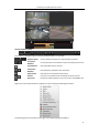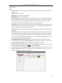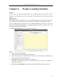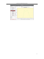
1
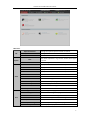
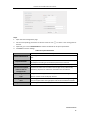
iVMS-5200 Control Client User Manual UD.6L0202D1422A01 User Manual of iVMS-5200 Control Client Hikvision® Network Digital Video Recorder User Manual This manual, as well as the software described in it, is furnished under license and may be used or copied only in accordance with the terms of such license. The content of this manual is furnished for informational use only, is subject to change without notice, and should not be construed as a commitment by Hangzhou Hikvision Digital Technology Co., Ltd. (Hikvision). Hikvision assumes no responsibility or liability for any errors or inaccuracies that may appear in the book. Except as permitted by such license, no part of this publication may be reproduced, stored in a retrieval system, or transmitted, in any form or by any means, electronic, mechanical, recording, or otherwise, without the prior written permission of Hikvision. HIKVISION MAKES NO WARRANTIES, EXPRESS OR IMPLIED, INCLUDING WITHOUT LIMITATION THE IMPLIED WARRANTIES OF MERCHANTABILITY AND FITNESS FOR A PARTICULAR PURPOSE, REGARDING THE HIKVISION SOFTWARE. HIKVISION DOES NOT WARRANT, GUARANTEE, OR MAKE ANY REPRESENTATIONS REGARDING THE USE OR THE RESULTS OF THE USE OF THE HIKVISION SOFTWARE IN TERMS OF ITS CORRECTNESS, ACCURACY, RELIABILITY, CURRENTNESS, OR OTHERWISE. THE ENTIRE RISK AS TO THE RESULTS AND PERFORMANCE OF THE HIKVISION SOFTWARE IS ASSUMED BY YOU. THE EXCLUSION OF IMPLIED WARRANTIES IS NOT PERMITTED BY SOME STATES. THE ABOVE EXCLUSION MAY NOT APPLY TO YOU. IN NO EVENT WILL HIKVISION, ITS DIRECTORS, OFFICERS, EMPLOYEES, OR AGENTS BE LIABLE TO YOU FOR ANY CONSEQUENTIAL, INCIDENTAL, OR INDIRECT DAMAGES (INCLUDING DAMAGES FOR LOSS OF BUSINESS PROFITS, BUSINESS INTERRUPTION, LOSS OF BUSINESS INFORMATION, AND THE LIKE) ARISING OUT OF THE USE OR INABILITY TO USE THE HIKVISION SOFTWARE EVEN IF HIKVISION HAS BEEN ADVISED OF THE POSSIBILITY OF SUCH DAMAGES. BECAUSE SOME STATES DO NOT ALLOW THE EXCLUSION OR LIMITATION OF LIABILITY FOR CONSEQUENTIAL OR INCIDENTAL DAMAGES, THE ABOVE LIMITATIONS MAY NOT APPLY TO YOU. 1 User Manual of iVMS-5200 Control Client Contents Chapter 1 1.1 1.2 1.3 Chapter 2 2.1 2.2 Overview ....................................................................................................................... 4 Description .................................................................................................................... 4 Running Environment.................................................................................................... 4 Function Modules ......................................................................................................... 4 Live View ....................................................................................................................... 7 Login .............................................................................................................................. 7 Basic Operations in Live View........................................................................................ 7 2.2.1 Starting and Stopping the Live View ................................................................. 9 2.2.2 Auto-switch in Live View ................................................................................. 11 2.2.3 PTZ Control in Live View .................................................................................. 12 2.2.4 Manual Recording and Capture....................................................................... 14 2.2.5 Instant Playback .............................................................................................. 17 2.2.6 Other Functions in Live View........................................................................... 19 Chapter 3 Remote Playback ......................................................................................................... 20 3.1 Normal Playback ......................................................................................................... 20 3.2 Event Playback............................................................................................................. 23 3.3 Synchronous Playback ................................................................................................. 24 3.4 VCA Playback ............................................................................................................... 25 Chapter 4 E-map Management.................................................................................................... 27 4.1 Adding an E-map ......................................................................................................... 27 4.2 Hot Spot Function ....................................................................................................... 29 4.2.1 Adding Hot Spots ............................................................................................. 29 4.2.2 Modifying Hot Spots........................................................................................ 31 4.2.3 Previewing Hot Spots ...................................................................................... 32 4.3 Hot Region Function .................................................................................................... 34 4.3.1 Adding Hot Regions ......................................................................................... 34 4.3.2 Modifying Hot Regions .................................................................................... 34 4.3.3 Previewing Hot Regions................................................................................... 35 4.4 The Preset Function .................................................................................................... 36 Chapter 5 Alarm Center ............................................................................................................... 37 5.1 Alarm Information of Event ......................................................................................... 37 5.2 Alarm Information of Platform .................................................................................... 39 Chapter 6 People Counting Statistics ........................................................................................... 40 Chapter 7 Log Management ........................................................................................................ 42 Chapter 8 Local Configuration ..................................................................................................... 45 8.1 General Settings .......................................................................................................... 45 8.2 File Saving Path Settings .............................................................................................. 46 8.3 Keyboard and Joystick Shortcuts Settings ................................................................... 47 8.4 Alarm Sound Settings .................................................................................................. 47 Chapter 9 Status Detection .......................................................................................................... 49 9.1 Physical View ............................................................................................................... 49 9.2 Logical View................................................................................................................. 50 2 User Manual of iVMS-5200 Control Client Chapter 10 10.1 10.2 10.3 10.4 Web Client ............................................................................................................... 52 Login ............................................................................................................................ 52 Live View ..................................................................................................................... 53 Playback ...................................................................................................................... 57 Local Configuration ..................................................................................................... 59 3 User Manual of iVMS-5200 Control Client Chapter 1 Overview 1.1 Description As one of the key components of the iVMS-5200 Professional Surveillance Platform, iVMS-5200 Control Client provides multiple operating functionalities, including real-time live view, PTZ control, video playback and download, alarm receiving, log query, etc.. This user manual describes the function, configuration and operation steps of iVMS-5200 Control Client. To ensure the proper usage and stability of the client, please refer to the contents below and read the manual carefully before installation and operation. Note: Two control clients are available: C/S Control Client (from Chapter 2 to Chapter 9) and B/S Web Client (Chapter 10). 1.2 Running Environment Operating System: Microsoft Windows 7 / Windows 8 (32 / 64-bit) CPU: Intel Pentium IV 2.4 GHz or above Memory: 1G or above Display: 1024*768 resolution or above Web Browser: IE 8.0 or above version, Chrome 8.0 or above version, Firefox 3.5 or above version, Safari 5.02 or above version. Notes: For high stability and good performance, these above system requirements must be met. The software does not support 64-bit operating system; the above mentioned 64-bit operating system refers to the system which supports 32-bit applications as well. 1.3 Function Modules Control Panel of iVMS-5200 Control Client: 4 User Manual of iVMS-5200 Control Client Menu Bar: Open Local Picture File Open Video File Exit System Lock Switch User View Manage the video files recorded on local PC. Exit the iVMS-5200 Control Client. Lock screen operations. Log into the Control Client again to unlock. Switch the login user. 1024*768 Display the window at size of 1024*768 pixels. 1280*1024 Display the window at size of 1280*1024 pixels. 1440*900 Display the window at size of 1440*900 pixels. 1680*1050 Display the window at size of 1680*1050 pixels. Full Screen Display the window in full screen. Control Panel Main View Remote Playback E-map Alarm Center Auxiliary Screen Preview Log Search Local Configuration Status Detection Tool Manage the captured pictures stored on local PC. Enter Control Panel interface. Open Main View page. Open Remote Playback page. Open E-map page. Open the Alarm Center page. Open Auxiliary Screen Preview window. Open the Log Search page. Open the Local Configuration page. Open the Status Detection page. Broadcast Select the camera(s) to start broadcasting. I/O Control Enable / disable the alarm outputs. People Counting Player Open the People Counting Statistics page. Open the player to play the local video files. 5 User Manual of iVMS-5200 Control Client User Manual (F1) Help About Language Click to open the User Manual; you can also open the User Manual by pressing F1 on your keyboard. View the basic information of the Control Client. The default language of the Control Client is English. The iVMS-5200 Control Client is composed of the following function modules: The Main View module provides live view of network cameras and video encoders, and supports some basic operations, such as picture capturing, recording, PTZ control, etc. The Remote Playback module provides the search, playback, export of record files. The E-map module provides the displaying and management of E-maps, alarm inputs, hot regions and hot spots. The Alarm Center module provides the displaying and management of alarm information received by the Control Client. The Log Search module provides the query of system log files and the log files can be filtered by different types. The Local Configuration module provides the configuration of general parameters, file saving paths, alarm sounds and other settings for the Control Client. The Status Detection module provides the function of displaying the status of the server, connected devices and the cameras of the devices. The function modules are easily accessed by clicking the navigation buttons on the control panel or by selecting the function module from the View or Tool menu. You can check the information, including current user, network usage, CPU usage, memory usage and time, in the upper-right corner of the main page. 6 User Manual of iVMS-5200 Control Client Chapter 2 Live View 2.1 Login When opening iVMS-5200 Control Client, you can login with the user name and password of iVMS-5200 platform. Steps: 1. Input the user name and password of the iVMS-5200 platform. Notes: By default, the user name of the platform is admin and the password is 12345. You are highly recommended to change the default password right after the first login to avoid safety problem. Please refer to the User Manual of iVMS-5200 Web Manager for the operation of changing password. 2. Optionally, check the checkbox Remember password to keep the password. 3. Check the checkbox Enable Auto-login to log into the software automatically. 4. Click Show Server Address and set the address and port No of the server. Optionally, you can click Hide Server Address to collapse the field. Server Address: Enter the address of the server that you want to connect to. Port No.: Enter the port No. of the server. By default, it’s 80. 5. Click Login to enter the Control Client. 2.2 Basic Operations in Live View Purpose: For the surveillance task, you can view the live video of the added network cameras and video encoders on the Main View page. And some other basic operations are supported, including picture capturing, manual recording, PTZ control, etc. Click the icon on the control panel, or click View->Main View to open the Main View page. 7 User Manual of iVMS-5200 Control Client Main View Page 1 View List: Show the customized view and you can also create new view. 2 Camera List: Show the added devices. 3 PTZ Control Panel: Show the panel for PTZ control. 4 Display Window of Live View: The window for playing the live video of the camera(s). 5 Live View Toolbar: The buttons shown are used for controlling the live view. Camera Status: The camera is online and works properly. The camera is in live view. The camera is in recording status. The camera is offline. Live View Toolbar: On the Main View page, the following buttons are available: Set View Set the screen layout mode and save the new settings for the current view; save the current view as another new view. Stop Live View Stop the live view of all cameras. Previous Go for live view of the previous page. Next Go for live view of the next page. Resume/Pause Auto-switch Show /Hide the Menu Click to resume/pause the auto-switch in live view. Show/Hide the configuration menu of auto-switch. Click again to hide. Mute/Audio On Turn off/on the audio in live view. Full Screen Display the live view in full-screen mode. Press ESC key to exit. Right-click on the display window in live view to open the Live View Management Menu: 8 User Manual of iVMS-5200 Control Client The following items are available on the right-click Live View Management Menu: Stop Live View Stop the live view in the display window. Capture Capture the picture in the live view process. Print Captured Picture Capture the current picture and then print the picture. Start/Stop Recording Start/Stop the manual recording. The record file is stored in the PC. Open PTZ Control Open Digital Zoom Switch to Instant Playback Start/Stop Two-way Audio Enable/Disable Audio Camera Status Enable PTZ control function on the display window. Click again to disable the function. Enable the digital zoom function. Click again to disable the function. Switch to instant playback mode. You can select the playback time. Click to start/stop the two-way audio of the camera in live view. Click to enable/disable the audio in live view. Display the status of the camera in live view, including the recording status, signal status, connection number, etc. Arming Control Open the arming control window of the camera in live view. Full Screen Display the live view in full-screen mode. Click the icon again to exit. 2.2.1 Starting and Stopping the Live View Starting Live View for One Camera Steps: 1. Open the Main View page. 2. Optionally, click the icon in live view toolbar, then click the screen layout button select the screen layout mode for live view. 3. Click-and-drag the camera to the display window, and or double-click the camera name after selecting the display window to start the live view. Note: You can click-and-drag the video of the camera in live view to another display window if needed. 9 User Manual of iVMS-5200 Control Client Starting Live View for Area Steps: 1. Open the Main View page. 2. Click-and-drag the area to the display window, or double-click the area name to start the live view. You can also click-and-drag or double-click the ControlCenter node to start the live view of all the added devices. Note: The display window number is self-adaptive to the camera number of the area. Starting Live View in Custom View Mode Purpose: The view mode can be customized for the video live view. Note: The custom view you created will be saved to the iVMS-5200 platform and other users who have the corresponding permission can also get access to the view and the related live video. Steps: 1. Open the Main View page. 2. In the view panel, click the icon 3. Click Create Public View in the custom view list. 4. Input the view name and click Add. The new view is of 4-Screen mode by default. 5. Optionally, Click the icon in live view toolbar, then click the screen layout button select the screen layout mode for the new view. 6. 7. Click to save the screen layout mode for the new view. Click-and-drag the camera to the display window, to expand the custom view list. and or double-click the camera name in custom view mode to start the live view. 8. Click the icon another view. to save the new view. Optionally, you can click to save the current view as Right-click the custom view name on the list, and a menu pops up as follows: The following buttons are available on the right-click menu: Edit View Name Edit the name of the custom view. Delete View Delete the custom view. Save View Save the new settings of the custom view. Save View As. Save the current view as another custom view. Stopping the Live View Steps: 1. Select the display window. 2. Click the icon that appears in the upper-right corner when the mouse pointer is over the 10 User Manual of iVMS-5200 Control Client display window, or click Stop Live View on the right-click menu to stop the live view of the display window. You can also click the button in live view toolbar to stop all the live view. 2.2.2 Auto-switch in Live View Camera Auto-switch Purpose: The video stream of the cameras from the same area will switch automatically in a selected display window in camera auto-switch. Steps: 1. Open the Main View page. 2. Select a display window for camera auto-switch. 3. Click the icon 4. Select an area and click the icon 5. You can click the icon in the toolbar and select the switching interval. / on the area node. to pause/resume the camera auto-switch. View Auto-switch Purpose: The custom views will switch automatically in view auto-switch. The custom views need to be added before proceeding. Steps: 1. Open the Main View page. 2. Click the icon 3. Click the icon on the public view node. Note: If the number of the cameras is greater than that of the windows, the auto-switch will be in the toolbar and select the switching interval. performed in multiple windows. You can click 4. You can click the icon / or to view the auto-switch. to pause/resume the multi-view auto-switch. All Cameras Auto-switch Purpose: The video stream of all the added cameras will switch automatically in a selected display window in all cameras auto-switch. Steps: 1. Open the Main View page. 2. Select a display window for all cameras auto-switch. 3. Click the icon 4. Click the icon on the ControlCenter node. Note: If the number of the cameras is greater than that of the windows, the auto-switch will be in the toolbar and select the switching interval. performed in multiple windows. You can click 5. You can click the icon / or to view the auto-switch. to pause/resume the auto-switch of all the cameras. 11 User Manual of iVMS-5200 Control Client 2.2.3 PTZ Control in Live View The software provides PTZ control for cameras with pan/tilt/zoom functionality. You can set the preset, patrol and pattern for the cameras on the PTZ Control panel. And you can also open window PTZ control for the operations of PTZ cameras by clicking Open PTZ Control on the right-click menu. Click the icon to expand the PTZ Control panel. The following buttons are available on the PTZ Control panel: Direction Button and Auto-scan Zoom Focus Iris PTZ Speed Auxiliary Focus 3D Positioning Light Wiper Lens Initialization Configuring the Preset A preset is a predefined image position which contains information of pan, tilt, zoom, focus and other parameters. Perform the following steps to add a preset: 1. Click the Preset tab to enter the PTZ preset configuration panel. 2. Click the direction buttons on the PTZ control panel to move the camera to the desired view. 3. 4. Select a PTZ preset number from the preset list and click Input the name of the preset in the pop-up dialog box. 5. Click OK to save the settings. . To call a configured preset, double-click the preset, or select the preset and click the icon To modify a configured preset, select the preset from the list and click the icon To delete a configured preset, select the preset from the list and click the icon . . . 12 User Manual of iVMS-5200 Control Client Configuring the Pattern Patterns can be set to record the movement of the PTZ. Perform the following steps to add a pattern: 1. Click the Pattern button to enter the PTZ pattern configuration panel. 2. 3. Click to start recording of this pattern path. Use the direction buttons and other buttons to control the PTZ movement. 4. 5. Click to stop and save the pattern recording. Click the icon to call the pattern. To stop calling the pattern, click . Note: Only one pattern can be configured, and the newly-defined pattern will overwrite the previous one. Configuring the Patrol A patrol is a scanning track specified by a group of user-defined presets, with the scanning speed between two presets and the dwell time at the preset separately programmable. Before you start: Two or more presets for one PTZ camera need to be added. Perform the following steps to add and call a patrol: 1. Click the Patrol button to enter the PTZ patrol configuration panel. 2. Select a path number from the drop-down list. 13 User Manual of iVMS-5200 Control Client 3. 4. Click to add a preset, and set the dwell time and patrol speed. Repeat the above operation to add other presets to the patrol. 5. 6. Optionally, you can click or to edit or delete a preset in the patrol path. Click the icon to call the patrol. To stop calling the patrol, click . Notes: Up to 16 patrols can be configured. The preset dwell time can be set to 1~30 seconds, and the patrol speed can be set to level 1~40. 2.2.4 Manual Recording and Capture Toolbar in Each Live View Display Window: In each live view display window, the following toolbar buttons are available: Capture Capture the picture of the camera during live view. Start/Stop Recording Start/Stop manual recording. The record file is stored in the PC. Switch to Instant Switch to the instant playback mode. You can select the playback Playback time. Manual Recording in Live View Purpose: Manual Recording function allows you to record the live video on the Main View page manually and the record files are stored in the local PC. Steps: 1. Move the mouse pointer to the display window in live view to show the toolbar. 2. Click in the toolbar of the display window or on the right-click Live View Management Menu to start the manual recording. The icon 3. turns to . Click the icon to stop the manual recording. A prompt box with the saving path of the video files you just recorded will pop up if all the operations succeed. Notes: During the manual recording, an indicator appears in the upper-right corner of the display 14 User Manual of iVMS-5200 Control Client window. The saving path of video files can be set on the Local Configuration interface. For details, see Section 8.2 File Saving Path Settings. Viewing Local Record Files Steps: 1. Click File->Open Video File to open the Record Files page. 2. Select the camera to be searched from the Area list. 3. 4. Click the icon to specify the start time and end time for the search. Click Search. The video files recorded between the start time and end time will be displayed. Select the video file, and click Upload. You can upload the video file to the configured FTP server. You can also click Upload Queue to check the uploading status. Select the video file, and click Burn. You can burn the record file to a disc connected to your PC. You can also click Burning Progress to view the burning status. Select the video file, and click Save as. You can save a new copy of the video file in local PC. Select the video file, and click Delete. You can delete the video file. Note: To upload the video files to FTP server, the FTP settings need to be configured before proceeding. For details, see Section 8.2 File Saving Path Settings. Double-click the video file and the video file can be played back locally. 15 User Manual of iVMS-5200 Control Client The following buttons are available on the local playback page: CIF/4CIF Display the video at CIF/4CIF resolution. Full Screen Display the local playback page in full-screen mode. Close Close the local playback page of the record file. Pause/Play Pause / resume the playback of the record file. Stop Stop the playback of the record file. Speed Set the playback speed. Single Frame Play back the record file frame by frame. Digital Zoom Enable the digital zoom function. Click again to disable. Enable/Disable Audio Click to enable/disable the audio in the local playback. Capture Capture the picture of the playback video. Capturing Picture in Live View Steps: 1. Move the mouse pointer to the display window in live view to show the toolbar. 2. Click the icon in the toolbar of the display window or on the right-click Live View Management Menu. A small window of the captured picture will be displayed to notify whether the capturing operation is done or not. Note: The saving path of the captured pictures can be set on the Local Configuration interface. For details, see Section 8.2 File Saving Path Settings. Viewing Captured Pictures The pictures captured in live view are stored in the PC running the Control Client. You can view the captured pictures if needed. Steps: 1. Click File->Open Local Picture to open the Captured Picture page. 2. Select the camera to be searched from the Area list. 3. Click the icon to specify the start time and end time for the search. 16 User Manual of iVMS-5200 Control Client 4. Click Search. The pictures captured between the start time and end time will be displayed. 5. Double-click the captured picture to enlarge it for a better view. Select the captured picture, and click Upload. You can upload the picture to the configured FTP server. You can also click Upload Queue to check the uploading status. Select the captured picture, and click Burn. You can burn the picture to a disc connected to your PC. You can also click Burning Progress to view the burning status. Select the captured picture, and click Print. You can print the selected picture by the printer connected via the network. Select the captured picture, and click Save as. You can save a new copy of the picture in local PC. Select the captured picture, and click Delete. You can delete the selected picture. Note: To upload the pictures to FTP server, the FTP settings need to be configured before proceeding. For details, see Section 8.2 File Saving Path Settings. 2.2.5 Instant Playback Purpose: The record files can be played back instantly on the Main View page. Instant playback only shows the record in last 30s/1min./3min./5min./8min./10min. If no record is found, it means there is no record during the last 30s/1min./3min./5min./8min./10min. Thus, you can get an immediate review if needed. Before you start: The video files need to be recorded on the storage devices, such as the SD/SDHC cards and HDDs on the DVRs, NVRs, Network Cameras, etc., or on the storage servers. You should configure the record schedule for the device via Web Manager. For details, please refer to User Manual of iVMS-5200 Web Manager. Steps: 1. Start the live view and move the mouse pointer to the display window to show the toolbar. 2. Click the icon on the toolbar or on the right-click Live View Management Menu, and a list of time periods pops up. 30s, 1 min, 3 min, 5 min, 8 min, and 10 min are selectable. 17 User Manual of iVMS-5200 Control Client 3. Select a time period to start the instant playback. Example: If the current time of the live view is 09:30:00, and you select 3 min, then the instant playback will start from 09:27:00. 4. Click the icon Notes: again to stop the instant playback and go back for the live view. During the instant playback, an indicator window. The live view process will continue after the instant playback completed. appears in the upper-right corner of the display Right-click on the display window during instant playback to activate the following menu: The following buttons are available on the right-click Instant Playback Management Menu: Pause/Play Pause/Start the instant playback in the display window. Stop Stop the instant playback and return to the live view mode. Speed Up/Down Increase/Decrease the play speed of the instant playback. Single Frame Play back the record file frame by frame. Open Digital Zoom Enable the digital zoom function. Click again to disable the function. Capture Capture the picture in the instant playback process. Print Captured Picture Capture the current picture and then print the picture. 18 User Manual of iVMS-5200 Control Client Start/Stop Recording Start/Stop clipping the record files. Enable/Disable Audio Click to turn on/off the audio in instant playback. Switch to Live View Switch to live view mode. Full Screen Display the instant playback in full screen mode. Click again to exit. 2.2.6 Other Functions in Live View There are some other functions supported in the live view, including digital zoom, two-way audio, and camera status. Auxiliary Screen Preview The live video can be displayed on different auxiliary screens for the convenient preview of multiple monitoring scenes. Click View->Auxiliary Screen Preview to open an auxiliary screen. Up to 3 auxiliary screens are supported. Digital Zoom Right-click on the live view window and select Open Digital Zoom. Use the left key of mouse to drag a rectangle area in the lower-right/upper-left direction, and then the rectangle area will zoom in/out. Two-way Audio Right-click on the live view window and select Start Two-way Audio. Two-way audio function enables the voice talk of the camera. You can get not only the live video but also the real-time audio from the camera. This two-way audio can be used for only one camera at one time. Camera Status Right-click on the live view window and select Camera Status. The camera status, such as recording status, signal status, connection number, etc., can be detected and displayed for check. The status information refreshes every 3 minutes. Arming Control Right-click on the live view window and select Arming Control. The status of the enabled event detection (e.g., motion detection, video loss) displays, such as arming status, alarm name and alarm type. You can click Disarm / Disarm All to disable the event detection and set the disarming duration. You can also click Arm / Arm All to enable the event detection. 19 User Manual of iVMS-5200 Control Client Chapter 3 Remote Playback Purpose: The record files stored on the local device or the storage server can be searched by view, camera or triggering event, and then can be played back remotely. Before you start: You should set the record settings for the camera via the Web Manager. For details, please refer to the User Manual of iVMS-5200 Web Manager. Click the icon on the control panel, or click View->Remote Playback to open the Remote Playback page. Remote Playback Page 1 View List, Camera List and Event List 2 Calendar 3 Search Options 4 Search Result List 5 Display Window of Playback 6 Playback Toolbar 7 Timeline 3.1 Normal Playback Purpose: The record files can be searched by view or camera for the Normal Playback. Searching Record Files for Normal Playback Steps: 20 User Manual of iVMS-5200 Control Client 1. Open the Remote Playback page. 2. Click 3. Select the view or camera(s) to be searched from the list. 4. Select the day to be searched on the calendar. to expand the View List or Camera List on the left side. You can also click to show more search options, click the icon and end time for the search, and select the file type to be searched. 5. to specify the start time Click Search. The matched record files of the selected view or camera will be displayed on the Search Result List. You can filter the results through the Filter text field. Note: Up to 16 cameras can be searched simultaneously. Playing Back Record Files After searching the record files for the normal playback, you can play back the record files in the following two ways: Playback by File List Select the record file from the search result list, and then click the icon on the record file, or double-click the record file to play the video on the corresponding display window of playback. You can also select a display window and click the icon corresponding record file. in the toolbar to play back the Playback by Timeline The timeline indicates the time duration for the record files, and the record files of different types are color coded. Click on the timeline to play back the video of the specific time. You can click or to zoom in or zoom out the timeline bar. You can click or to go to the previous or the next time period. You can use the mouse wheel to zoom in or zoom out on the timeline. 21 User Manual of iVMS-5200 Control Client Normal Playback Toolbar: On the Normal Playback page, the following toolbar buttons are available: Playback Speed Async/Sync Playback Stop Playback Pause/Start Playback Set the playback speed for the selected display window. Click to play back the record files synchronously/asynchronously. Stop the playback of all cameras. Pause/Start the playback of the record files. Single Frame Play back the record files frame by frame. Volume Click to turn on/off the audio and adjust the audio volume. Full Screen Display the video playback in full-screen mode. Press ESC to exit. Right-click on the display window in playback to open the Playback Management Menu: The following items are available on the right-click Playback Management Menu: 22 User Manual of iVMS-5200 Control Client Reverse Playback Play back the record file reversely. Pause/Start Pause/Start the playback. Stop Stop the playback. Speed Up Play back the record file at a faster speed. Speed Down Play back the record file at a slower speed. Single Frame Play back the record file frame by frame. Open Digital Zoom Enable the digital zoom function. Click again to disable the function. Accurate Positioning Set the accurate time point to play back the record file. Capture Capture the picture in the playback process. Print Captured Picture Capture a picture and print it. Start/Stop Recording Start/Stop the manual recording. The record file is stored in the PC. Download the record files of the camera and the record files are Download stored in the PC. You can select to download by file or by date. Enable/Disable Audio Click to enable/disable the audio in playback. Full Screen Display the playback in full-screen mode. Click the icon again to exit. 3.2 Event Playback Purpose: The recordings triggered by event, such as motion detection, video loss or alarm input, can be searched for Event Playback and this function requires the support of the connected device. Searching Record Files for Event Playback Steps: 1. Open the Remote Playback page. 2. Click 3. Select the event type from the drop-down list, and select the cameras or alarm input sensors. 4. Select the day to be searched on the calendar. to expand the Event List on the left side. You can also click to show more search options, and then click the icon start time and end time for the search. 5. to specify the Click Search. The recordings from the selected cameras or sensors triggered by event will be displayed on the Search Result List. You can filter the results through the Filter text field. Playing Back Record Files After searching the recordings triggered by the event, you can play back the record files in the following two ways: Playback by File List Select the record file from the search result list, and then click the icon in the toolbar, or double-click the record file to play the video on the display window of playback. Playback by Timeline The timeline indicates the time duration for the record file. Click on the timeline to play back the video of the specific time. You can click or to zoom in or zoom out the timeline bar. 23 User Manual of iVMS-5200 Control Client You can click or to go to the previous or the next time period. You can use the mouse wheel to zoom in or zoom out on the timeline. Event Playback Toolbar: On the Remote Playback page, the following toolbar buttons are available: Playback Speed Stop Playback Pause/Start Playback Single Frame Previous Event Set the playback speed for the selected display window. Stop the playback of all cameras. Pause/Start the playback of record files. Play back the record files frame by frame. Go to the playback of the previous event. Next Event Go to the playback of the next event. Volume Click to turn on/off the audio and adjust the audio volume. Full Screen Display the video playback in full-screen mode. Press ESC to exit. 3.3 Synchronous Playback Purpose: In synchronous playback, the record files can be played back in synchronization. Note: Record files from up to 16 cameras can be played back simultaneously. Steps: 1. Search the record files for the normal playback. 2. Click 3. Select the record file from the list and click , or click on the timeline to start the synchronous playback for all searched cameras. 4. To disable the synchronous playback, click the icon in the toolbar to enable the synchronous playback. The icon turns to . . 24 User Manual of iVMS-5200 Control Client 3.4 VCA Playback Purpose: You can set VCA rule to the searched record files and find the video that VCA event occurs, including VCA Search, Intrusion and Line Crossing. This function helps to search out the video that you may be more concerned, mark it with red color and the playback speed of the concerned video and unconcerned video can be customized. VCA Search: Get all the related motion detection events that occurred in the pre-defined region. Intrusion: Detect whether there are people, vehicles and other moving objects intruding into the pre-defined region. Line Crossing: Bi-directionally detect people, vehicles and other moving objects that cross a virtual line. Steps: 1. Search the record files for the normal playback and play back the record file(s). 2. Select a playback window and click 3. Select the VCA Type, draw the detection region and set the sensitivity. to expand the VCA Playback panel. Notes: For VCA Search, click , and then click and move on the playback window to set the grid rectangle as the detection region. Or you can click camera as the detection region. 4. to set all the area shot by the For Intrusion, click detection region. For Line Crossing, click and then click on the playback window to set the beginning point in the area and move the mouse and click again to set the end of the line. and then click on the playback window to set the vertex for the To delete the drawn region, click to remove it. Optionally, click to expand the More Search Options panel. You can configure the advanced 25 User Manual of iVMS-5200 Control Client settings for the VCA Search. Skip Unconcerned Video: Check the checkbox and the video that no VCA event occurs will be skipped during playback. Speed of Unconcerned Video: Set the playback speed for the unconcerned video as desired. Speed of Concerned Video: Set the playback speed for the concerned video as desired. Pre-play: Set the time to play back before the VCA event. For example, when a VCA event occurs at 10:00, if you set the pre-play time as 5 seconds, the video plays back from 9:59:55. Post-play: Set the time to play back after the VCA event. For example, when a VCA event ends at 11:00, if you set the post-play time as 5 seconds, the video plays back till 11:00:05. 5. Click Search and the VCA events occurred in the defined area will be red marked on the timeline. 26 User Manual of iVMS-5200 Control Client Chapter 4 E-map Management Purpose: The E-map function gives a visual overview of the locations and distributions of the installed cameras, alarm input devices and alarm output devices. You can get the live view of the cameras on the map, and you will get a notification message from the map when alarm is triggered. Click the icon on the control panel, or click View->E-map to open the E-map page. E-map Page 1 E-map List 2 Map Display Area 3 E-map Toolbar 4.1 Adding an E-map Purpose: An E-map needs to be added as the parent map for the hot spots and hot regions. Note: The added e-map you created will be saved to the iVMS-5200 platform and other users who have the corresponding permission can also get access to the e-map. Steps: 1. Open the E-map page. 2. Click Edit Map to enable the map editing mode. 3. Select the E-map icon and click 4. Select an area for the map from the drop-list, and input a descriptive name of the added map as to open the Add Map dialog box. desired. 5. Click the icon and select a map file from the local path. You can check the map preview. 27 User Manual of iVMS-5200 Control Client 6. Click OK to save the settings. Note: The picture format of the map can only be *.png, *.jpg, *.bmp or *.svg. The map added is displayed in the Map Display Area. Use the mouse wheel to zoom in or zoom out on the map. You can click-and-drag the yellow window in the lower-right corner or use the direction buttons and zoom bar to adjust the map area for view. To select multiple elements on the map, you can click (it changes to ) and then click-and-drag on the map area to select the elements. You can also edit the name of the map as desired on the Property panel. Click the button Edit Map or Map Preview in the E-map toolbar to enter the map editing mode or map preview mode. E-map Toolbar in Map Editing Mode: E-map Toolbar in Map Preview Mode: The following table introduces the buttons on the e-map page: Add Map Add a new map. Modify Map Edit the map information, including the map name and file path. Delete Map Delete the current map. Add Camera Hot Add a camera as the hot spot on the map. 28 User Manual of iVMS-5200 Control Client Spot Add Alarm Input Hot Spot Add Alarm Output Hot Spot Add an alarm input sensor as the hot spot on the map. Add an alarm output device as the hot spot on the map. Add Hot Region Add an existing map as the hot region on the map. Add Label Add a label with description to the map, hot spot or hot region. Delete Delete the selected hot spot or hot region. Clear Alarm Info Clear the alarm information displayed on the map. Refresh Refresh all the e-map information. Preset Display the added presets of the all the maps. Save as Preset Save the current scene as a preset which Previous Next Capture & Edit The client can remember the switching records of the maps. Click to go to the previous record. The client can remember the switching records of the maps. Click to go to the next record. Capture the current scene including the elements (e.g., camera, alarm input), edit on the captured picture, and save it to the local PC. 4.2 Hot Spot Function Purpose: The cameras, alarm inputs and alarm outputs can be added on the map and are called the hot spots. The hot spots show the locations of the cameras, alarm inputs and alarm outputs, and you can also get the alarm information of the surveillance scenarios through the hot spots. 4.2.1 Adding Hot Spots Adding Cameras as Hot Spots Steps: 1. Click the Edit Map button in the E-map toolbar to enter the map editing mode. 2. 3. Select a map and click the icon in the toolbar to open the Add Hot Spot dialog box. Check the checkbox to select the camera(s) to be added. You can also search the camera by entering the key words in the Linked Camera filed. 4. Optionally, you can edit the hot spot name, select the hot spot icon, choose the name color and add description to the hot spot. You can also click Icon Management to upload the local picture file to set it as the customized icon. Note: The picture format of the icon can only be *.png, *.jpg, or *.bmp and the picture size should be 32*32 pixels. 5. Click OK to save the settings. The camera icons are added on the map as hot spots. You can click-and-drag the camera icons to move the hot spots to the desired locations. Click to select the 29 User Manual of iVMS-5200 Control Client hot spot and you can see and edit the settings on the Property panel. Adding Alarm Inputs as Hot Spots Steps: 1. Click the Edit Map button in the E-map toolbar to enter the map editing mode. 2. 3. Select a map and click the icon in the toolbar to open the Add Hot Spot dialog box. Check the checkbox to select the alarm input(s) to be added. You can also search the alarm input by entering the key words in the Linked Alarm Input filed. 4. Optionally, you can edit the hot spot name, select the hot spot icon, choose the name color and add description to the hot spot. You can also click Icon Management to upload the local picture file to set it as the customized icon. Note: The picture format of the icon can only be *.png, *.jpg, or *.bmp and the picture size should be 32*32 pixels. 5. Click OK to save the settings. The alarm input icons are added on the map as hot spots. You can click-and-drag the alarm input icons to move the hot spots to the desired locations. Click to select the hot spot and you can see and edit the settings on the Property panel. Adding Alarm Outputs as Hot Spots Steps: 1. Click the Edit Map button in the E-map toolbar to enter the map editing mode. 2. Select a map and click the icon in the toolbar to open the Add Hot Spot dialog box. 30 User Manual of iVMS-5200 Control Client 3. Check the checkbox to select the alarm output(s) to be added. You can also search the alarm output by entering the key words in the Linked Alarm Output filed. 4. Optionally, you can edit the hot spot name, select the hot spot icon, choose the name color and add description to the hot spot. You can also click Icon Management to upload the local picture file to set it as the customized icon. Note: The picture format of the icon can only be *.png, *.jpg, or *.bmp and the picture size should be 32*32 pixels. 5. Click OK to save the settings. The alarm output icons are added on the map as hot spots. You can click-and-drag the alarm input icons to move the hot spots to the desired locations. Click to select the hot spot and you can see and edit the settings on the Property panel. 4.2.2 Modifying Hot Spots Purpose: You can modify the information of the added hot spots on the map, including the name, the color, the icon, etc. Steps: 1. Click the Edit Map button in the E-map toolbar to enter the map editing mode. 2. Click the hot spot icon on the map and the settings of the hot spot display on the Property panel. 3. You can edit the hot spot name in the text field and select the color, the icon, the linked camera, alarm input or alarm output and the description of the hot spot. 4. Click Save to save the new settings. To delete the hot spot, right-click the hot spot and click Delete, or select the hot spot and click in the toolbar. 31 User Manual of iVMS-5200 Control Client 4.2.3 Previewing Hot Spots Steps: 1. Click the Map Preview button in the E-map toolbar to enter the map preview mode. 2. Move your mouse to the hot spot and a window pops up on which the related functions of the hot spot display. For camera and alarm input hot spot: You can select to check the live view of the camera, view its description, configure the arming control, view and save the log information of the history alarm. For alarm input hot spot: You can view its description, configure the arming control, view and save the log information of the history alarm. For alarm output hot spot: You can enable or disable the linked alarm output. Or you can right-click a hot spot and the following functions available on the right-click menu: For camera hot spot: You can select to check the live view of the camera, configure the arming control, view and save the log information of the history alarm, clear all the alarm information of the camera. For alarm input hot spot: You can select to configure the arming control, view and save the log information of the history alarm, clear all the alarm information of the camera. 3. For alarm output hot spot: You can enable or disable the linked alarm output. If there is any alarm triggered, the hot spot icon changes to mouse to it to check the alarm information. and twinkles. You can move your Arming Control Purpose: Arming control provides the fucntion to arm and disarm hot spots, clear alarm information, and enable and disable the alarm outputs. Steps: 1. On the pop-up window or right-click menu of the hot spot, click or select Arming Control to activate the Arming Control window. 2. The status of the enabled event detection (e.g., motion detection, video loss) displays, such as arming status, alarm name and alarm type. You can click Disarm / Disarm All to disable the event detection and set the disarming duration. You can also click Arm / Arm All to enable the event 32 User Manual of iVMS-5200 Control Client detection. Example: If you set the disarming duration as 1 hour, then the event detection will be enabled again after 1 hour. History Alarm Purpose: You can check the logs related to the alarm and save them to the local PC as desired. Steps: 1. On the pop-up window or right-click menu of the hot spot, click or select History Alarm to activate the History Alarm window. 2. Select the alarm type to be serached, set the start time and end time, click Search to start searching the log files of the alarm. 3. The search results display on the list panel and you can check the detailed information. 4. Optionally, select the log file(s) and click Backup Log to save the logs to the local PC. 33 User Manual of iVMS-5200 Control Client 4.3 Hot Region Function Purpose: The hot region function links a map to another map. When you add a map to another map as a hot region, an icon of the link to the added map is shown on the main map. The added map is called child map while the map to which you add the hot region is the parent map. Note: A map can only be added as the hot region for one time. 4.3.1 Adding Hot Regions Before you start: At least 2 maps have been added. Refer to Chapter 5.1 Adding an E-map for detailed configuration about adding maps. Steps: 1. Click the Edit Map button in the E-map toolbar to enter the map editing mode. 2. Select an added map as the parent map. 3. 4. Click the icon in the toolbar to open the Add Hot Region dialog box. Check the checkbox to select the child map(s) to be linked. 5. Optionally, you can edit the hot region name, and select the hot region color and icon, and add description to the hot region. You can also click Icon Management to upload the local picture file to set it as the customized icon. Note: The picture format of the icon can only be *.png, *.jpg, or *.bmp and the picture size should be 32*32 pixels. 6. Click OK to save the settings. The child map icons are added on the parent map as the hot regions. You can click-and-drag the child map icons to move the hot regions to the desired locations. 4.3.2 Modifying Hot Regions Purpose: You can modify the information of the hot regions on the parent map, including the name, the color, 34 User Manual of iVMS-5200 Control Client the icon, etc. Steps: 1. Click the Edit Map button in the E-map toolbar to enter the map editing mode. 2. Click the hot region icon on the parent map and the settings of the hot region display on the Property panel. 3. You can edit the hot region name in the text field and select the color, the icon and the linked child map and the description of the hot region. 4. Click Save to save the new settings. To delete the hot region, right-click the hot spot and click Delete, or select the hot spot and click in the toolbar 4.3.3 Previewing Hot Regions Steps: 1. Click the Map Preview button in the E-map toolbar to enter the map preview mode. 2. Move your mouse to the hot region and a window pops up on which the related functions display. You can view its description and go to the linked child map. Or you can right-click a hot region and you can select to go to the linked child map and clear all the alarm information of the hot region. 3. The hot spots can also be added on the hot regions. 4. You can click the icon in the toolbar to go back to the parent map. 35 User Manual of iVMS-5200 Control Client 4.4 The Preset Function Purpose: The preset of the e-map provides the function to set the commonly used location of the map as a preset to make the preview of the locations more easily and conveniently. Steps: 1. Click the Map Preview button in the E-map toolbar to enter the map preview mode. 2. Select a map and adjust to the desired location which you want to set as the preset. You can adopt the following ways to adjust: click-and-drag the map or the yellow window in the lower-right corner, or click the direction buttons to adjust the position; use the mouse wheel or zoom bar to zoom in or zoom out. 3. 4. Click in the toolbar to save the current location as the preset and you can set a customized name for it. Note: Up to 10 presets can be added. To view the added preset, click in the toolbar and select a preset for preview. When you move the mouse over the preset, you can click the displayed to delete the preset. 36 User Manual of iVMS-5200 Control Client Chapter 5 Alarm Center Purpose: The alarm information received by the iVMS-5200 Control Client displays. You can check the detailed information of the alarm, manage the alarm information, etc. Click the icon on the control panel, or click View->Alarm Center to open the Alarm Center page. Alarm Center Page 1 Alarm List 2 Alarm Toolbar 3 Switch Alarm and Information Tab 4 Alarm Handling Bar Refer to the following table for the description of the icons on the alarm handling bar: Clear Alarm Info Enable Audio Clear all the alarm information. Enable audible warning of the Control Client when alarm is triggered. Enable Alarm Triggered The image of the selected camera(s) pops up when alarm is Pop-up Image triggered. Manual Alarm Set manual alarm. You can edit alarm description, set the alarm level and send it to the specified user 5.1 Alarm Information of Event Purpose: The event information of the connected device displays, such as motion detection, video loss, video 37 User Manual of iVMS-5200 Control Client tampering, etc. Steps: 1. 2. 3. 4. Open the Alarm Center page and the alarm that received by the Control Client displays on the alarm list. Index: The No. of the alarm. Alarm Time: The start time of the alarm. Alarm Name: The name of the alarm. Alarm Content: The content of the alarm. For manual alarm, the content includes the name of the user who sent the alarm and the alarm type; for VCA alarm, the content includes the device information, the alarm triggered device and the rule name; for other alarm, the content includes the device information and the alarm triggered device. Alarm Status: The status of the alarm, including Start, Unconfirmed; Start, Confirmed; Stop, Unconfirmed; Stop, Confirmed. Start means the alarm has not stopped yet and Confirmed means the alarm has been confirmed by the user. Alarm Level: The level including low, medium and high which indicates the urgent degree of the alarm. Handle Alarm: You can check the device information and the alarm type. You can also view the live view of the alarm triggered camera, start two-way audio with the alarm triggered camera when configuring the two-way audio as the linkage action, and view the picture of VCA alarm which has configured with alarm picture. For detailed configuration, please refer to User Manual of iVMS-5200 Web Manager. Acknowledgement Information: Display the acknowledgment information of the alarm. Click to select the alarm and click Acknowledge in the toolbar to confirm the alarm, or click Describe and Acknowledge to edit the description and confirm the alarm. To delete the alarm, click to select the alarm and click Delete in the toolbar, or right-click the alarm and click Clear. Or you can click to delete all the alarms. For arming control, click Arming Control to activate the Arming Control window. You can click Disarm / Disarm All to disable the event detection and set the disarming duration. You can also click Arm / Arm All to enable the event detection. 38 User Manual of iVMS-5200 Control Client 5.2 Alarm Information of Platform Purpose: You can check the error and warning information during the operation of the iVMS-5200 platform, such as connecting device failure, searching record files error, etc. Steps: 1. Open the Alarm Center page and click the Information tab. 2. You can check the details of the information. To delete the information, right-click the information and click Clear, or click to delete all the information. 39 User Manual of iVMS-5200 Control Client Chapter 6 People Counting Statistics Purpose: You can check the people counting statistics of the added people counting server and the statistics can be displayed in line chart or histogram. The detailed data can be exported for local storage. Before you start: Please added a people counting server to the iVMS-5200 platform and properly configure the corresponding area. The added server should have been configured with people counting rule. Note: For adding people counting server to the iVMS-5200 platform, please refer to the User Manual of iVMS-5200 Web Manager. For configuring people counting rule, please refer to the User Manual of People Counting Server. Click Tool->People Counting to open the People Counting page. Steps: 1. Open the People Counting page. 2. Click to select a camera of the people counting server. 3. Select the report type as needed and set the time. Three report types are available: daily report, monthly report and annual report. 4. Click Search and the statistics displays on the right panel. By default, the statistics are shown in line chart form. You can switch it to histogram by clicking the radio button. 5. (Optional) Click Export Report to save the detailed data of people counting to local PC. 40 User Manual of iVMS-5200 Control Client 41 User Manual of iVMS-5200 Control Client Chapter 7 Log Management Purpose: The log files of the iVMS-5200 platform and the devices that connected to the platform can be searched for checking. The CMS (Central Management Server) Logs refer to the log files of the platform, the Remote Logs refer to the log files of the connected devices and are stored on the local device. Click the icon on the control panel to open the Log Search page, or click Tool->Log Search to open the Log Search page. Searching CMS Log Files Steps: 1. Open the Log Search page. 2. Select the radio button of CMS Logs. 3. Select the Log Type and the corresponding search condition. There are 3 log types available, including Alarm Log, Operation Log and System Log. 4. 5. Alarm Log: You can select the alarm type for query, such as motion detection, video loss, etc. Operation Log: You can select the Operation type and the User Name. System Log: You can select the System Type and the User Name. Click the icon to specify the start time and end time. Click Search. The matched log files will display on the list. You can check the operation time, description and other information of the logs. Note: Please narrow the search condition if there are too many log files. 42 User Manual of iVMS-5200 Control Client Searching Remote Log Files Steps: 1. Open the Log Search page. 2. Select the radio button of Remote Logs. 3. Select the device for searching the log files. 4. Select the Major Type and the corresponding Minor Type. 5. 6. Click the icon to specify the start time and end time. Click Search. The matched log files will display on the list. You can check the operation time, log type and other information of the logs. Note: Please narrow the search condition if there are too many log files. Backing up Log Files Purpose: 43 User Manual of iVMS-5200 Control Client The log files, including the CMS logs and remote logs, can be exported to local PC. Steps: 1. Search the needed log files. 2. Click Backup Log to open the Backup Log dialog box. 3. 4. Click the icon and select a local saving path. Click Backup to export the found log files. 44 User Manual of iVMS-5200 Control Client Chapter 8 Local Configuration Purpose: The general parameters, file saving paths, keyboard and joystick shortcuts and alarm sounds can be configured. Click the icon on the control panel, or click Tool->Local Configuration to open the Local Configuration page. Note: You can click Default Value to restore the defaults of all the local configurations. 8.1 General Settings Purpose: The frequently-used parameters, including the view scale, network performance, etc., can be set. Steps: 1. Open the Local Configuration page. 2. Click the General tab to enter the General Settings interface. 3. Configure the general parameters. For details, see Table 7.1 General Parameters. 4. Click Save to save the settings. 45 User Manual of iVMS-5200 Control Client Table 7.1 General Parameters Parameters View Scale Network Performance Play Performance Picture Format Enable Screen Toolbar Display Enable Auto-login Prioritize the Playback of Record Files on Descriptions The view scale of the video in live view or playback. It can be set as Full Screen, 4:3, 16:9 or Original Resolution. According to the current network conditions to set it as Normal, Better or Best. The play performance of the live video. You can set is as Shortest Delay or Self-adaptive according to the hardware performance of the PC. Set the file format for the captured pictures during live view or playback. Show the toolbar on each display window in live view or playback when the mouse over the window. Remember the user name and password of the iVMS-5200 platform and log into the Control Client automatically. Play back the video files recorded on the storage server preferentially. Otherwise, play back the video files recorded on the local device. Storage Server Auto-change Stream Type Record Two-way Audio Change the stream type automatically in live view according to window division and the size of the display window. Record the audio during two-way audio. 8.2 File Saving Path Settings Purpose: The manual recording files, the captured pictures during live view and playback and the audio file recorded during two-way audio are stored on the local PC. The saving paths of these files can be set. Steps: 1. Open the Local Configuration page. 2. Click the File tab to enter the File Saving Path Settings interface. 3. 4. Click the icon and select a local path for the corresponding files. For FTP settings, enter the IP address, port No., the login user name and password of the FTP server, set a saving path for the uploaded pictures and video files. 5. Click Save to save the settings. 46 User Manual of iVMS-5200 Control Client 8.3 Keyboard and Joystick Shortcuts Settings Purpose: DS-1003KI and DS-1004KI keyboard, PC keyboard and USB joystick can be used to control the PTZ cameras. You can set the shortcuts for PC keyboard and USB joystick to get quick and convenient access to the commonly used actions. Steps: 1. For keyboard: Select the COM port from the drop-down list if DS-1003KI or DS-1004KI keyboard is connected to the PC installed with the Control Client. 2. For PC keyboard and USB joystick: 1) Select a certain function from the list. 2) Double-click the item field under the PC Keyboard or USB Joystick column. 3) Select the compound keys operation or number from the drop-down list to set it as the shortcuts for the function of the PC keyboard or USB joystick. 3. Click Save to save the settings. 8.4 Alarm Sound Settings Purpose: When the alarm, such as motion detection alarm, video exception alarm, etc., is triggered, the client 47 User Manual of iVMS-5200 Control Client can be set to give an audible warning and the sound of the audible warning can be configured. Steps: 1. Open the Local Configuration page. 2. Click the Alarm Sound tab to enter the Alarm Sound Settings interface. 3. Select the radio button of Video Engine or Local Audio Files. Notes: For Video Engine, the function should be support by the operating system of your PC. If you select Video Engine, the PC will play the voice text configured on the Web Manager when the alarm is triggered. For Local Audio File settings, please follow steps 4 and steps 5. 4. Click the icon and select the audio files from the local path for different alarms. 5. Optionally, you can click the icon 6. Click Save to save the settings. for a testing of the audio file. Note: The format of the audio file can only be *.wav. 48 User Manual of iVMS-5200 Control Client Chapter 9 Status Detection Purpose: The status of the server, connected devices and the cameras of the devices displays, such as the working status of the servers, the online status of the encoding devices, the status of recording schedule of the cameras, etc. Two kinds of view are available to show the status: the physical view shows the status of the servers and the devices, and the logical view shows the status of the cameras belonging to the areas. Click the icon on the control panel, or click Tool->Status Detection to open the Status Detection page. 9.1 Physical View Steps: 1. Open the Status Detection page. 2. Click the Physical View tab. You can check the working status of the servers, the online status of the devices and the servers, and the recording schedule of the cameras. 3. 4. 5. Optionally, you can click Refresh to get the latest status. On the device tree panel, click to select the device or server, and the information of this type of devices or servers displays. Note: The listed information varies depending on the devices or servers. Example: If you select Encoding Device on the device tree panel, all the connected encoding devices are listed. You can check the nickname, IP address or domain name, serial No., network status and HDD status of the devices. You can also click to get the latest status of the device. Optionally, you can check the checkbox of Exception Only to display the devices or servers in exceptional status only. You can also enter the key words in the Filter field to search the 49 User Manual of iVMS-5200 Control Client device or server. 9.2 Logical View Steps: 1. Open the Status Detection page. 2. Click the Logical View tab. You can check the online status of the cameras, the signal status of the cameras, the recording schedule of the cameras and the recording status of the cameras that are configured with recording schedule. 3. 4. 5. Optionally, you can click Refresh to get the latest status. On the area tree panel, click to select an area, and the information of cameras belonging to the area displays. You can also click to get the latest status of the device. Address/Domain Name: The IP address or domain name of the device that the camera belongs to. Device Serial No.: The serial No. of the device that the camera belongs to. Connection: Connection number refers to the number of the streams gotten from the device for live view, playback or record via network. If you set the connection number as 4, it means 4 streams are gotten from the device for remote live view, playback or record. If Stream Media Server displays in the field, it means the streams gotten from the device via the stream media server. Optionally, you can check the checkbox of Exception Only to display the cameras in exceptional status only. You can also enter the key words in the Filter field to search the camera. 50 User Manual of iVMS-5200 Control Client 51 User Manual of iVMS-5200 Control Client Chapter 10 Web Client Purpose: The iVMS-5200 platform can also provide the Web Client for being accessed through web browser. It provides the functionalities of live view, playback, and local configuration. Environment Requirements Operating System: Microsoft Windows 7 / Windows 8 (32 / 64-bit) CPU: Intel Pentium IV 2.4 GHz or above Memory: 1G or above Display: 1024*768 resolution or above Web Browser: IE 8.0 or above version, Chrome 8.0 or above version, Firefox 3.5 or above version, Safari 5.02 or above version. 10.1 Login Steps: 1. In the address bar of the web browser, input the address of the CMS (Central Management Server) and press the Enter key. A login window displays. Note: The address is in the format of http://IP address of CMS/client. Example: If the IP address of CMS is 172.6.21.96, and you should enter http://172.6.21.96/client in the address bar. 2. Input the user name and password of CMS. Notes: By default, the user name for login is admin and the password is 12345. You are highly recommended to change the default password right after the first login to avoid safety problem. 3. Optionally, check the checkbox of Remember password to save the password. 4. Click Login. For the first time to login, you should install the plug-in before you can access the functions. Click 52 User Manual of iVMS-5200 Control Client Please click here to download and install the plug-in. Close the browser when installing the plug-in. on the live view page, run and install the plug-in according to the prompt. After the installation of plug-in, re-open the web browser and log into the platform. Note: Please close your web browser during the installation of the plug-in. 10.2 Live View Purpose: On the Live View page, you can view the live video of the added cameras and do some basic operations, including picture capturing, recording, PTZ control, etc. Before you start: An area with cameras assigned to is required to be defined for live view. Click the Live View tab to open the Live View page. Starting Live View Steps: 1. Open the Live View page. 2. Optionally, move your mouse to mode. 3. Click-and-drag the camera to the display window, icon in the live view toolbar, and select a screen layout or double-click the camera name after selecting the display window to start the live view. 53 User Manual of iVMS-5200 Control Client Live View Toolbar: On the Live View page, the following toolbar buttons are available: Set the screen layout mode. 7 types of screen layout modes are Set Layout selectable: 1-Screen, 4-Screen, 6-Screen, 8-Screen, 9-Screen, 13-Screen and 16-Screen. Stop/Start Live View Stop/Start the live view of all cameras. Capture Capture the picture in the live view process. Start/Stop Recording Start/Stop the manual recording. The record file is stored in the PC. Previous Go for live view of the previous page. Next Go for live view of the next page. Audio on/Mute Turn on/off the audio in live view. Digital Zoom Enable/Disable the digital zoom function. Full Screen Display the live view in full-screen mode. Press ESC to exit. Move the mouse over the display window during live view, the following icons show. Capture Capture the picture in the live view process. Instant Playback Open the instant playback window, enter the time duration and click Search to find and play back the record file. Two-way Audio Start two-way audio with the camera. Next Stop the live view of the camera. PTZ Control Functionality Purpose: Cameras with the pan/tilt/zoom functionality can be controlled through the web browser. You can also set the preset, patrol and pattern for the cameras. Click the Icon icon to expand the PTZ Control panel on the Live View page. Description Icon Description Icon Description 54 User Manual of iVMS-5200 Control Client Direction button and the Zoom+, Focus+, Zoom-, Focus-, auto-scan button Iris+ Iris- The speed of the PTZ movement Auxiliary Focus 3D Positioning Light on /off Wiper Preset Settings Pattern Settings Lens Initialization Patrol Settings Configuring the Preset Perform the following steps to add a preset: 1. Click the Preset button to enter the PTZ preset configuration panel. 2. Click the direction buttons to move the camera to the desired view. 3. Click to select a PTZ preset No. from the preset list and click the icon 4. In the pop-up dialog box, edit the name for the preset and click OK to save the settings. . Note: Up to 256 presets can be added. To call a configured preset, select the preset from the list and click the icon To delete a configured preset, select the preset from the list and click the icon . . Configuring the Pattern 1. Click the Pattern button to enter the PTZ pattern configuration panel. 55 User Manual of iVMS-5200 Control Client 2. 3. Click to start recording of this pattern path. Use the direction buttons to control the PTZ movement. 4. Click to stop and save the pattern recording. 5. Click the icon to call the pattern. To stop calling the pattern, click . Note: Only one pattern can be configured, and the newly-defined pattern will overwrite the previous pattern. Configuring the Patrol Before you start: Two or more presets for one camera need to be added. Perform the following steps to add and call a patrol: 1. Click the Patrol button to enter the PTZ patrol configuration panel. 2. Select a track number from the drop-down list. 3. Click 4. Repeat the above operation to add other presets to the patrol. 5. Optionally, you can click to add a preset, and set the dwell time and patrol speed for the preset. 6. Click the icon Notes: or to edit or delete the preset in the patrol path. to call the patrol. To stop calling the patrol, click . Up to 16 patrols can be configured. The preset dwell time can be set to 1~30 sec, and the patrol speed can be set to level 1~40. 56 User Manual of iVMS-5200 Control Client 10.3 Playback Purpose: The record files stored on the storage devices such as the HDDs, Net HDDs and SD/SDHC cards on the local device or the storage server can be searched and played back remotely through the web browser. Click the Playback tab to open the Playback page. Playback Toolbar: On the Playback page, the following toolbar buttons are available: Set Layout Set the screen layout mode. 4 types of screen layout modes are selectable: 1-Screen, 4-Screen, 9-Screen and 16-Screen. Stop Playback Stop the playback of all cameras. Capture Capture the picture in the playback process. Start/Stop Clipping Start/Stop clipping the record files. Download Open the download window. Select the record file(s) and click Download to save the file(s) to the local PC. Audio on/Mute Turn on/off the audio in playback. Full Screen Display the playback in full-screen mode. Press ESC to exit. Searching Record Files Steps: 1. Open the Playback page. 2. Select the camera(s) to be searched from the list. 3. Click to select a day for the search. 4. Optionally, click to activate the More Search Options panel. Click the icon start time and end time, and select the query type. 5. Click Search. The record files of the selected cameras will be displayed on the Search Result list. to specify the You can filter the results through the Search text field. Note: Up to 16 cameras can be searched simultaneously. 57 User Manual of iVMS-5200 Control Client Playing Back Record Files After searching the record files, you can play back the record files in the following two ways: Playback by File List Select the record file from the search result list, and then click the icon to play the video on the display window of playback. Playback by Timeline The timeline indicates the time duration for the record file. Click on the timeline to play back the video of the specific time. You can click or to scale up or scale down the timeline bar. You can use the mouse wheel to zoom in or zoom out on the timeline. 58 User Manual of iVMS-5200 Control Client Move the mouse pointer to the display window in playback to show the toolbar. Toolbar in Each Playback Display Window: In each playback display window, the following toolbar buttons are available: Reverse Playback Play back the record file reversely. Click and click to stop the playback to start reverse playback. Pause/Start Playback Pause/Start the playback of the record files. Stop Playback Stop the playback of the camera. Slow Forward Play back the record file at a slower speed. Fast Forward Play back the record file at a faster speed. Single Frame Play back the record files frame by frame. 10.4 Local Configuration Purpose: The general parameters, such as network performance, play performance, capture mode and saving paths of files, can be configured through the web browser. Click the Local Configuration tab to open the Local Configuration page. 59 User Manual of iVMS-5200 Control Client Steps: 1. Open the Local Configuration page. 2. Set the corresponding parameters as desired. Click the icon the files. 3. Optionally, you can click Default Value to restore the defaults of all system parameters. 4. Click Save to save the settings. to select a local saving path for Table 10.1 System Parameters Parameters Network Performance Play Performance Picture Format Prioritize the Playback of Record Files on Descriptions According to the current network conditions to set it as Normal, Better or Best. The play performance of the live video. You can set is as Shortest Delay or Self-adaptive according to the hardware performance of the PC. Set the file format for the captured pictures during live view or playback. Play back the video files recorded on the storage server preferentially. Otherwise, play back the video files recorded on the local device. Storage Server Auto-change Stream Type Saving Path of Video Files Saving Path of Pictures Change the stream type automatically in live view according to window division and the size of the display window. The saving path of video files recorded by manual recording during live view, the clipped video during playback and the downloaded record files. The saving path of the captured pictures in live view or playback. 0300001040520 60 User Manual of iVMS-5200 Control Client 61