1
ARC-22: 250 Mhz Fiber Optic Timing Board, Gen III
This manual describes the fiber optic timing board, model ARC-22. The board serves
three main functions – communicating between the controller and the host computer,
generating timing waveforms and providing overall controller supervision. It has a
duplex fiber optic link to a PCI interface board, the ARC-64, that operates at a bit rate of
250 MHz, providing a sustained maximum image data transfer rate of 12.5 Mpixels per
second. It controls the timing of the analog portions of the controller by writing 24-bit
digital words as often as every 40 nanoseconds over a backplane to other controller
boards. It performs such supervisory functions as exposure timing, power sequencing,
controlling a shutter, and synchronizing operations with signals external to the controller
using a Digital Signal Processor, the Motorola DSP56303, operating at an internal clock
speed of 100 MHz.
SOFTWARE FILE NAMES:
Much of the operation of the timing board can be understood by reviewing the software
that executes on the board’s DSP. There are several input and output files for supporting
the operation of the timing board, as follows:
timboot.asm
This file generates the EEPROM code that is loaded into the DSP
when the system boots. It contains DSP configuration and
initialization procedures, a command interpreter and execution
code for the following commands: test data link, read memory,
write memory, load application and stop idle clocking.
tim.asm
This has the code for reading out the array, clocking the array in
the idle state, readout related parameters, and a table of all
application commands.
timCCDmisc.asm
Targeted towards CCD applications, this file has a medly
of routines not directly involved with array readout, such as
exposure control, power on/off and paramete configuration
control.
timIRmisc.asm
Targeted towards IR array applications, this file has a medly
of routines not directly involved with array readout, such as
exposure control, power on/off and parameter configuration
control.
Generic.waveforms
Here are the definitions of the waveform tables that are read by
the timing board DSP and written to the controller hardware to
control the clock driver and DC bias voltages, and all operations
ARC-22 User's Manual
1
Updated June 29, 2013
of the readout. It is very specific to the particular array under
control
timrom.asm
A simple file called by the "timrom" script that just includes the
files "timhdr.asm" and "tim.asm" for generating EEPROM code.
tim
A simple script for generating a file that is downloaded to the
timing board named *.lod that takes all the files listed above as
input source code.
timrom
A simple script for generating a file named tim.s that is
suitable for programming the timing board EEPROM in an
external programmer and the file named 'tim.rom' that can be
written to the EEPROM by the DSP over the fiber optic link with
the program TimRomBurn.
tim.lod
The output file from the "tim" script, this file can be downloaded
over the optical fiber link into the timing board DSP memory for
execution.
tim.rom
Similar in format to the "tim.lod" file this is produced as an output
of the "timrom" script and is suitable for writing to the timing
board EEPROM with the "TimRomBurn program.
tim.s
Produced as an output of the "timrom" script this file is in
Motorola S-record format suitable for being written to the timing
board EEPROM with external programmers.
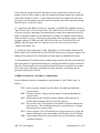
COMMAND PROTOCOL:
The command and reply protocol used to communicate over serial links between the
timing board and the PCI board and between the timing board and the utility board
within the controller is governed by the following convention, where $ designates hex
and all words of the command string are 24-bits in length:
$ss02nn
'command'
arg1
arg2
arg3
arg4
arg5
ss
nn
command
arg#
source number of the entity issuing the command
total number of words in the command, 7 >= nn >= 2
three character ASCII command, always upper case
optional 24-bit arguments
The source or destination number for this timing board is always 2. Command processing
ARC-22 User's Manual
2
Updated June 29, 2013
is all done in code located in the "timboot.asm" file, which is loaded into the DSP
memory when the DSP boots after power-up. A handshaking system exists to inform the
sender of commands that they are received and that processing can occur. Most
commands reply with a 'DON' when they finish executing, though there are some
exceptions to this. Several commands are executed by "timboot" program, as follows.
TDL number "Test Data Link". The DSP will read "number" and transmit it back to the
source in order to test functionality of the processor and communications path.
RDM address - "Read DSP Memory". Read from internal DSP or ROM memory. The
most significant nibble of the address designates the memory space, as follows:
Bit #20 = 1 selects P: memory.
Bit #21 = 1 selects X: memory.
Bit #22 = 1 selects Y: memory.
Bit #23 = 1 selects ROM memory.
WRM address value - "Write Memory". Write "value" to internal DSP or EEPROM
memory, following the same encoding of the memory space as RDM.
LDA # - "Load Application". This transfers the application program from the ROM to the
DSP memory, as well as the X: and Y: memory contents. # is the number of the
application to be loaded and is between 1 and 4.
STATUS LEDs:
Nex to the fiber optic data link parts are located two LEDs, one green and one red. The
green one being on indicates that the DSP has successfully booted from the EEPROM on
the board and is alive and healthy. Conversely, if +5V power is applied to the board and
the green LED is not shining it indicates a malfunctioning board. The LED is controlled
by a programmable I/O bit in the DSP, so can be turned off in software if its desired.
The red LED monitors the function of the incoming fiber optic data. The LED being ON
indicates that proper signals are not being received from the PCI board. A red LED on
the PCI board has the same function.
In summary, a properly functioning and connected timing board will have the green LED
on and the red LED off.
CONFIGURATION CONTROL:
There are "Controller Configuration" bits set up in the timing board application
command that can be read by the host computer to determine the capabilities of the
ARC-22 User's Manual
3
Updated June 29, 2013
controller hardware and software. These bits are encoded into a 24-bit word read by the
computer with the 'RCC' = 'Read Controller Configuration' command. The configuration
control bits are defined with equate directives in the "timhdr.asm" file, and below is
shown an example of the usage with the video processor.
In the "timhdr.asm" file there are several lines that define the configuration bits:
BIT #'s
2,1,0
FUNCTION
Video Processor
000 ARC41, CCD Rev. 3
001
CCD Gen I
010 ARC42 = dual readout CCD
011 ARC44 = 4-readout IR coadder
100 ARC45 = dual readout CCD
101 ARC46 = 8-channel IR
110 ARC48 = 8 channel CCD
111
ARC47 = 4-channel CCD
ARC22
ARC32
ARC45
ARC47
EQU
EQU
EQU
EQU
$000010
$008000
$000004
$000007
; Gen III timing board
; CCD & IR clock driver board
; 2-channel CCD video board
; 4-channel CCD video board
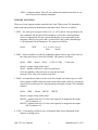
In the file "tim.asm" for the generic CCD controller these bits are used to define "CC":
CC
EQU ARC22+ARC32+ARC47+SHUTTER_CC
CONFIG
DC
CC
; Controller configuration
and in the file "tim.asm" the 'RCC' command is entered in the command list,
DC
'RCC',READ_CONTROLLER_CONFIGURATION
while in the file "timCCDmisc.asm" the 'RCC' command is finally defined:
; Let the host computer read the controller configuration
READ_CONTROLLER_CONFIGURATION
MOVEY:<CONFIG,X0
; Just transmit the configuration
JMP <FINISH
SOFTWARE STATUS BITS:
Also in the file "timhdr.asm" are defined bits for the STATUS word located at X:
ARC-22 User's Manual
4
Updated June 29, 2013
memory location 0 of the timing board DSP. These are mainly used to control execution
of the timing board code with bit conditional jump instructions (JCLR and JSET). Some
of the bits are set by the host computer by reading the X:STATUS word, changing the
desired bit, and writing the word back to the controller. Other bits are controlled by the
DSP to indicate execution status. Such things as shutter mode, MPP operation, CCD
readout architecture are controlled with these bits.
POWER ON and OFF:
The file "timCCDmisc.asm" includes commands for powering the power control board
on and off, which causes the analog supply voltages (+/-6.5V, +/-16.5V and +36V) to
switch these voltages onto or off of the backplane. These commands ('PON' and 'POF')
are also resident in the utility board, so the host computer can issue them to either board
and have them execute properly. This capability is included to protect the image sensors
from damaging voltage combinations or sudden voltage spikes, as the power control
board turns on the power in sequence with writing voltage values to the DACs and
closing output protection switches on the analog boards. Also, the power control board
turns on the voltages with a timescale of about 10 milliseconds. Note that the +5V digital
power is not switched but instead is turned on at all times to all the boards in the
controller.
There is a routine named CLEAR_SWITCHES that writes zeroes to all the analog
switches on the video processors and clock driver boards. This is needed to minimize
power dissipation in these parts that occurs when their +5V digital control lines are
powered but their analog supplies are not. This same routine is executed in the
"timboot.asm" code when the DSP first boots up. The CLEAR_SWITCHES is also
called on power off.
The power-on procedure consists of the following:
1. Write zeroes to all the analog switches and DACs.
2. Write zeroes to the LVEN (Low voltage enable, for the +/-6.5V and +16.5V
supplies), and then to HVEN for the +36V supply to turn them on.
3. Check the power control board signal POWEROK to ensure that the power
was indeed turned on correctly. If not, report an error.
4. Close the output analog swtiches that connect the clock driver and DC bias
supply output circuits to the sensor.
5. Write all DAC values from the "DACS" table to the DACs. The "DACS" table
is located in the "Generic.waveforms" file, and delay.
SHUTTER CONTROL:
Shutters can be controlled from the timing or utility boards. Shutter control with the
utility board is accomplised with an open collector circuit (74F07 and a pull up resistor
ARC-22 User's Manual
5
Updated June 29, 2013
supplied near the shutter driver circuit by the user) driving the SHUTTER line on the
front of the utility board available on the small printed circuit board that plus into its
DIN-96 connector and is wired to a small circular 6-pin HIROSE connector mounted
next to the fiber optic connectors on the controller housing. Alternatively, shutters can be
controlled with the timing board, wherein the shutter control signal, also named
SHUTTER, is routed from U12 pin #15 to the backplane pin A30. From here it is routed
through the power control board to the small power supply to a shutter driver circuit that
translates this TTL level signal to a +24-volt burst followed by a +5 volt holding signal
to open solenoid-driven shutters. This shutter driver signal is routed from the small
power supply box back to the power control board were it is wired to the small circular
HIROSE connector mounted next to the fiber optics connectors on the controller
housing. Finally, the TTL-level signal SHUTTER from the timing board is also available
directly on the power control board (only for Rev. 7 power control boards), which is also
routed to the same HIROSE circular connector. The HIROSE connector is wired as
following:
pin #1 - White wire to utility board front connector, ground
pin #2 - Grey wire to utility board front connector, open collector shutter
pin #4 - White wire to power control board J6, +34 volt shutter driver pulse
pin #5 - Grey wire to power control board J6, ground for shutter driver pulse
pin #3 - Blue wire to power control board J8 pin #2, ground
pin #6 - Purple wire to power control board J8 pin #1, TTL SHUTTER
The shutter control software is located in the file "timCCDmisc.asm". The shutter is
opened by writing a zero to bit #4 of the LATCH (which is connected to U12) and a one
to close the shutter, taking care not to disturb the other bits. The shutter can be controlled
directly by the host computer with the 'OSH' and 'CSH' commands, or from DSP
software by the subroutines 'OSHUT' and 'CSHUT'. The shutter is opened at the
beginning of an exposure and closed at the end of it if the SHUT bit #11 of the
X:STATUS word is set. Code in the "tim.asm" file delays readout by Y:SHDEL
milliseconds after the shutter is first instructed to close to allow it to close completely
before charge is moved on the CCD to prevent image smearing.
EXPOSURE CONTROL:
The sequence of commands and software execution from the beginning of an exposure to
its completion will be described here. The sequence will be described assuming that the
timing board is controlling the exposure. Alternatively the utility board could be used,
and its operation is described in the utility board user's manual.
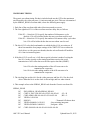
1. The host computer sets the desired exposure time by issuing the 'SET' = Set exposure
time command to the timing board with an argument of milliseconds.
0x203
'SET'
Number of milliseconds
ARC-22 User's Manual
6
Updated June 29, 2013
2. The timing board executes the SET_EXPOSURE_TIME located in
"timCCDmisc.asm" routine by simply storing the value in the EXPOSURE_TIME
constant.
3. The host computer sets the shutter status to either open the shutter or not during the
exposure by reading the X:STATUS value, setting or clearing bit #11, and writing the
value back to the same location.
4. The host computer issues the 'SEX' = start exposure command to the timing board.
0x202
'SEX'
Start exposure
5. Upon receiving the 'SEX' command the START_EXPOSURE routine located in
"timCCDmisc.asm" issues a 'IIA' = initialize image address command to the PCI board.
The PCI board will set the PCI image address equal to the base PCI address and the
number of pixels transferred to zero.
6. Continuing in the START_EXPOSURE routine located in "timCCDmisc.asm", the
CCD is cleared with the CLR_CCD routine, keeping care to periodically check for
incoming commands so the abort readout or abort exposure command can be executed
promptly.
7. The variable X:<IDL_ADR is written with the address #<TST_RCV so that when the
timing board processes normal comamnds after the exposure begins that the timing board
will not be executing the IDLE routine in the "tim.asm" file that exercises the parallel
and serial clocks.
8. The shutter is opened if bit #11 = SHUT bit is set.
9. The EXPOSE routine in the file "timCCDmisc.asm" is entered, which loads the
EXPOSURE_TIME into the DSP timer register, enables the timer, and monitors the
timer status for the end of the timer countdown. During the countdown incoming
commands are checked for in case an abort expsoure command is issued, and the serial
clocks are exercised, but not the parallel clocks.
10. When the countdown is complete the START_EXPOSURE routine is re-entered,
causing the shutter to be closed if the SHUT bit of X:STATUS has been set, and causing
execution to jump to the RDCCD routine in the file "tim.asm".
11. At the start of the RDCCD routine in "tim.asm" a bit is set to indicate that readout has
begun and the PCI_READ_IMAGE routine in "timCCDmisc.asm" is executed. This
routine sends the 'RDA' command with arguments containing the total number of pixels
ARC-22 User's Manual
7
Updated June 29, 2013
to be read in the image to the PCI board that sets up a counter that awaits these total
number of pixels until it signals to the host computer that image readout has completed.
Notice that with this revision 1.7 of the software that the host computer does not write
any image size information to the PCI board, but instead writes this to the timing board
that then writes it to the PCI board.
12. Continuing in the RDCCD routine in "tim.asm", a SYNTHETIC_IMAGE routine in
"timCCDmisc.asm" will be executed if the TST_IMG bit #10 of X:STATUS is set, which
will cause an image consisting of incremented pixel counts to be transmitted to the PCI
board. If a noirmal readout is desired then there is a delay of Y:SHDEL milliseconds to
allow the shutter to close, a clearing out of the charge in the serial shift register, and then
a simple readout of Y:NPR rows and Y:NCOLS in each row. The PARALLEL and
SERIAL_READ routines that are called to exercise the clocks are located in the
"Generic.waveforms" file.
13. At the end of the readout the X:<IDL_ADR address is filled with the address of the
IDLE routine if the #IDLMODE bit of X:STATUS has been set by the host computer, the
reading out in progress bit is cleared and execution jumps to command processing.
14. Meanwhile the PCI board has been reading image data from the fiber optics data link
and writing them to sequential PCI addresses, counting the number of pixels transferred.
When the desired number has been transferred the host flags are changed from reading
out to done status, and normal command execution continues. An interrupt may be
generated at this point if desired.
OTHER EXPOSURE CONTROL COMMANDS:
Several additional exposure commands are implemented in "timCCDmisc.asm", as
follows:
'PEX' = Pause exposure. Simply close the shutter if needed and disable the
exposure timer.
'REX' = Resume exposure. Simply open the shutter if needed and enable the
exposure timer.
'RET' = Read exposure time. Read the current contents of the exposure, in
milliseconds remaining until the end of the exposure.
'SET' = Set exposure time. The argument is the number of milliseconds desired
in the exposure. This command need only be issued if there is a change
from the previous exposure time.
'AEX' = Abort exposure. This will terminate the current exposure by closing the
shutter, disabling the timer and sending a 'DON' reply to the PCI board.
'ABR' = Abort readout. Similar to abort readout, this will terminate the readout
currently in progress
ARC-22 User's Manual
8
Updated June 29, 2013
'CRD' = Continue readout. This will just continue the readout from where it was
left off by the abort readout command.
SUPPORT ROUTINES:
There are several support routines included in the "timCCDmisc.asm" file intended to
make setup and operation of the hardware somewhat easier. There are as follows:
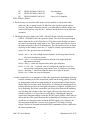
1. 'SGN' = Set video processor gain. Gains of x1, x2, x4.75 and x9.5 are specified by the
first command, and the speed of the integrator is set by the second argument,
where 0 is appropriate for slow system (introducing 4.9 pf capacitance in the
integrator, causing a low gain) and 1 is entered for a fast system (introducing a
1.0 pf capacitance in the integrator). The syntax is as follows:
0x204
'SGN'
{1, 2, 5 or 10} {0 or 1}
Gain
Speed
2. 'SBN' = Set bias number is useful for updating the digital value in any of the DACs in
the video processors or clock driver boards. The syntax is as follows:
0x206
'SBN'
#board
#DAC
{'VID' or 'CLK'}
12-bit value
#board = jumper setting of the board
#DAC = number of the DAC on the selected board
select for updating video processor or clock driver boards
enter the 12-bit value to be written to the DAC
3. 'SMX' = Set multiplexer number on the clock driver board will connect any two clock
driver signals to SMB connectors on the front of the board, useful for viewing the
signals on an oscilloscope for verifying timing and signal overlaps. The command
syntax is:
0x204
'SMX'
#board
#MUX1
#MUX2
#board = jumper setting of the board
#MUX1 = number from 0 to 23 of the clock signal to be mapped to the output
MUX connector #1.
#MUX2 = number from 0 to 23 of the clock signal to be mapped to the output
MUX connector #2.
4. 'CSW' = Clear analog switches to zero, to minimize their power dissipation in the
absence of analog power.
ARC-22 User's Manual
9
Updated June 29, 2013
WAVEFORM TIMING:
The generic waveform timing file that is included reads out the CCD at the maximum
rate allowed by the video processor, 1.0 microseconds per pixel. This rate is determined
by the SERIAL_READ waveform table, where the following notes apply:
1. Each line of the waveform table takes 40 microseconds to execute.
2. The first eight bits #23-16 of the waveform word are delay bits, as follows:
If bit #23 = 1 then bits 22-16 specify the number of 640 nanosec cycles
that bits 15-0 will be held at before the next waveform word is read.
If bit #23 = 0 then bits 22-16 specify the number of 40 nanosec delay cycles that
bits 15-0 will be held at before the next waveform word is read.
3. The bits #15-12 select the board number to which the bits #11-0 are written to. If
these bits match the four jumper settings of the "SWITCH" bits on either the
clock driver or video processor boards, then the selected board will latch bits
#11-0 into its internal registers.
4. If the bits #15-12 are all set (= 0xF) then a special selection is made of writing the
bits #11-0 to the circuitry on the timing board that exercises the serial
transmission of A/D video data over the fiber optics data link (SXMIT):
bits #5-0 select the starting number of the A/D converter to be
transmitted in a sequence.
bits #10-6 select the ending number of the A/D converter to be
transmitted in a sequence.
5. The clocking bits are bits #6-0 for the video processor and bits #11-0 for the clock
driver. When the bit is set the clock is driven high, and low when cleared.
6. This example refers to the SERIAL_READ code from the Generic.waveform file.
SERIAL_READ
DC
END_SERIAL_READ-SERIAL_READ-1
DC
CLK2+S_DLY+SW+RG+00+S2+S3+00+S5+00 ; L2 = H
DC
CLK2+00000+SW+00+00+S2+S3+00+S5+00
; RG = L
DC
VIDEO+%1110100
DC
$00F0C0
; Transmit A/D data to host
DC
VIDEO+$000000+%1110111
; Stop resetting integrator
DC
VIDEO+$050000+%0000111
; Integrate - delta
DC
CLK2+$010000+00+00+S1+00+00+S4+00+S6
ARC-22 User's Manual
10
Updated June 29, 2013
DC
VIDEO+$010000+%0011011
DC
VIDEO+$070000+%0001011
DC
VIDEO+$000000+%0011011
END_SERIAL_READ
; Stop Integrate
; Integrate
; Stop, A/D is sampling
a. The first entry in a waveform table needs to be the number of words in the table,
minus one. Rev. 4 timing boards (50 Mhz fiber optic speed) required a minus
two here. The simple construction below is recommended. Each line defines one
word of DSP memory, using the DC = Define Constant directive to the Motorola
assembler.
b. The board selection is made with CLK2 = $002000 for the clock driver board and
VIDEO = $000000 for the video processor board. The clock driver board signal
names define one bit of the clock driver's 12-bit data word to be high, so when a
zero shows up instead the clock signal is low. These names generally are close to
the names assigned by the CCD manufacturer. The video processor bits are listed
explicitly in this example, where the "%" signifies a binary representation of the
string. The video processor bits are defined as
Bit #6 = xfer => on a low-to-high transition transfer 16-bit image data from the
A/D converter output to a latch.
Bit #5 = A/D => on a low-to-high transition start the A/D sample/hold and
subsequent conversion.
Bit #4 = integ => when low integrate on the dual slope integrator.
Bit #3, 2 = Pol+, Pol- => with the value 01 configure the amplifier circuit in a
non-inverting configuration, and with the value 10 configure it inverting.
Bit #1 = Dcclamp => when low clamp the input video signal to ground
Bit #0 = rst => when low reset the integrator
c. In this example there is an integration of the video signal before the dumping of charge
from the summing well to the output node with a non-inverting polarity, followed
by an integration with an inverting polarity for an equal amount of time after the
charge dump. Notice that a trick is played here of clocking the summing well low
to dump the charge before the first signal integration is complete. Normally this is
not a good thing, but in this system there was a long delay between the summing
well clocking and a change in the video signal, allowing some time to be saved
with this sequence. It is a good idea to verify this by examining the integrate
signal on the integrator analog switch (the INTEG signal) with the video signal to
ensure that the video signal transition due to summing well clocking occurs well
outside the two integration times when the INTEG signal is low. Similarly, the
first integration should not occur too close to the last CCD charge clocking,
which is why the A/D transmisstion and SXMIT commands are place right before
the first integration time.
ARC-22 User's Manual
11
Updated June 29, 2013
d. The two integration times should be of equal duration. In this example they are both
320 nanosec long. The first integration time consists of a delay of 5, a seconds
delay of 1, for a total delay of 6 x 40 nsec = 240 nsec plus two 40 nsec instruction
times, one for the instruction to begin the integration and one for the summing
well clocking instruction. The second integration time is just the delay time of 7 x
40 nsec plus the instruction time of 40 nsec.
Voltage Settings:
The voltages of the DACs on the video and clock driver boards are set in the routine
named SET_BIASES in the file "timCCDmisc.asm" by reading from the DACS
table in Genric.waveforms. The voltages are specified in a table in units of
decimal volts, as
; Define the clocking voltages
SW_HI
EQU +3.0 ; Summing well, +6, -3 for anti-backspill
SW_LO
EQU -8.0
and then in the DACS voltage table as
DACS
DC
DC
DC
END_DACS-DACS-1
(CLK2<<8)+(0<<14)+@CVI((SW_HI+10.0)/20.0*4095)
(CLK2<<8)+(1<<14)+@CVI((SW_LO+10.0)/20.0*4095)
These two lines construct the word that is to be transmitted over the serial SSI link to the
clock driver board to be written to the selected DAC, following the protocol that is
described in the clock driver user's manual. The CLK2<<8 simply left shifts the CLK2
definition of 0x002000 so the 2 is in the bit position #23-20 required for serial words,
and the (0<<14) shifts the DAC number 0 into the bit locations #19-12. The next
argument is to the assembler directive @CVI for constructing a 12-bit integer for the
value to be written to the DAC corresponding to a high voltage of SW_HI = +3.0 volts ,
and a 20 volt bipolar output range. The second line above simply writes the low clock
voltage to the next DAC location, so the clock driver can switch between the two
voltages according to the value of the bit in the clocking waveform.
OTHER FEATURES:
Short descriptions of several advanced features of the timing board are listed below, yet
without including complete documentation. For more information please consult
Bob Leach at ARC.
The artwork of the board has a provision for the installation of a second fiber optic
transmitter circuit to allow image data to be sent over two data links concurrently. This
ARC-22 User's Manual
12
Updated June 29, 2013
second channel can be populated on request. Two PCI boards in the host computer are
required, with one servicing commands, replies and image data, and the second one
servicing only image data. A modified PAL U16 needs to be installed, which monitors a
DSP bit that specifies whether dual transmitter operation is enabled.
The DB-15 connector P1 located on the front of the board next to one of the fiber optic
connectors provides a variety of signalling and interconnections options. There are two
general purpose digital inputs to the timing board (EXT-IN0 and 1) that connect to ports
on the DSP. There are similar outputs as well (EXT-OUT0 and 1). One of the inputs is
routed to an interrupt input to the DSP, to allow it to be externally interrupted. There is a
duplex asynchronous serial link that can be operated from a port on the DSP to
communication to other systems directly from the controller. Finally, there is support for
synchronizing two or more controller, described below.
Two or more controllers can be operated synchronously. This involves designating one of
them to be a master, and one or more to be slaves. The 25 MHz clock oscillator on the
master needs to be wired to each of the slaves through the DB-15 connector on the front
of each board. Similarly, the master will control the signal EXT-OUT0 that will be
received by each slave to signal when image readout is to begin.
The traffic on the fiber optic data link can be monitored on two headers, J3 and J4,
marked "XMT" and "RCV". Pin #10 is ground, pin #9 is a low true data strobe, and pins
#1-8 show each data byte received or transmitted over the fiber optic link. In cases where
the board doesn't seem to be communicating at all with the PCI board, a useful
troubleshooting strategy is to monitor the strobe pins for activity in response to
commands issued from the host computer. The simple 'TDL' command or 'hardware test'
issued from the computer should result in a packet of strobe signals on the RCV header,
followed by a similar packet a few microseconds on the XMT header if the timing board
successfully processes the command and generates a reply.
ARC-22 User's Manual
13
Updated June 29, 2013