1
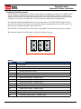
RoboClaw Series
Brushed DC Motor Controllers
RoboClaw
RoboClaw
RoboClaw
RoboClaw
2x5A
2x15A
2x30A
2x60A
User Manual
Firmware 4.1.4 and Newer
Hardware V4 and Newer
User Manual Revision 4
(c) 2014 IonMC. All Rights Reserved
RoboClaw Series
Brushed DC Motor Controllers
RoboClaw Revision History.......................................................................5
Precautions............................................................................................8
Motor Selection......................................................................................8
Stall Current..........................................................................................8
Running Current.....................................................................................8
Wire Lengths..........................................................................................8
Run Away..............................................................................................9
Power Sources.......................................................................................9
Optical Encoders.....................................................................................9
RoboClaw
RoboClaw
RoboClaw
RoboClaw
RoboClaw
2x5A Hardware Overview........................................................ 10
2x5A Dimensions................................................................... 11
2x15A and 2x30A Hardware Overview....................................... 12
2x15A and 2x30A Dimensions.................................................. 13
2x60A and HV 2x60A Dimensions............................................. 15
Header Overview.................................................................................. 16
Logic Battery (LB IN)............................................................................ 16
BEC Source (LB-MB)............................................................................. 16
Encoder Power (+ -) ............................................................................ 16
Encoder Inputs (EN1 / EN2)................................................................... 16
Control Inputs (S1 / S2 / S3)................................................................. 16
Main Battery Screw Terminals................................................................. 17
Disconnect........................................................................................... 17
Motor Screw Terminals.......................................................................... 17
Status and Error LEDs........................................................................... 18
Error States......................................................................................... 18
Warning States..................................................................................... 18
RoboClaw Modes................................................................................... 19
Configuring RoboClaw Modes.................................................................. 20
Mode Options....................................................................................... 21
Battery Cut Off Settings......................................................................... 21
USB RoboClaw Power............................................................................ 23
USB RoboClaw Connection..................................................................... 23
USB Comport and baudrate.................................................................... 23
RC Mode.............................................................................................. 25
Using RC Mode with feedback for velocity/position control.......................... 25
RC Mode With Mixing............................................................................ 25
Pulse Ranges....................................................................................... 26
RC Wiring Example............................................................................... 27
Analog Mode........................................................................................ 30
Using Analog Mode with feedback for velocity/position control.................... 30
Analog Mode With Mixing....................................................................... 30
Analog Wiring Example.......................................................................... 31
Standard Serial Mode............................................................................ 33
Serial Mode Baud Rates......................................................................... 33
Standard Serial Command Syntax........................................................... 33
Standard Serial Wiring Example.............................................................. 34
Standard Serial Mode With Slave Select................................................... 35
RoboClaw Series User Manual
2
RoboClaw Series
Brushed DC Motor Controllers
Standard Serial - Arduino Example.......................................................... 36
Packet Serial Mode................................................................................ 38
Address............................................................................................... 38
Packet Serial Baud Rate......................................................................... 38
Checksum Calculation........................................................................... 39
Packet Timeout.................................................................................... 39
Packet Acknowledgement....................................................................... 39
Commands 0 - 7 Compatibility Commands............................................... 40
0 - Drive Forward M1............................................................................ 40
1 - Drive Backwards M1......................................................................... 40
2 - Set Minimum Main Voltage ............................................................... 40
3 - Set Maximum Main Voltage............................................................... 40
4 - Drive Forward M2............................................................................ 40
5 - Drive Backwards M2......................................................................... 41
6 - Drive M1 (7 Bit) .............................................................................. 41
7 - Drive M2 (7 Bit) .............................................................................. 41
Commands 8 - 13 Mix Mode Compatibility Commands............................... 42
8 - Drive Forward................................................................................. 42
9 - Drive Backwards.............................................................................. 42
10 - Turn right...................................................................................... 42
11 - Turn left........................................................................................ 42
12 - Drive Forward or Backward (7 Bit).................................................... 42
13 - Turn Left or Right (7 Bit)................................................................. 42
Packet Serial Wiring.............................................................................. 43
Packet Serial - Arduino Example............................................................. 44
Version, Status, and Settings Commands................................................. 46
21 - Read Firmware Version................................................................... 46
24 - Read Main Battery Voltage Level...................................................... 46
25 - Read Logic Battery Voltage Level...................................................... 47
26 - Set Minimum Logic Voltage Level..................................................... 47
27 - Set Maximum Logic Voltage Level..................................................... 47
49 - Read Motor Currents...................................................................... 47
55 - Read Motor 1 P, I, D and QPPS Settings............................................ 47
56 - Read Motor 2 P, I, D and QPPS Settings............................................ 47
57 - Set Main Battery Voltages............................................................... 48
58 - Set Logic Battery Voltages............................................................... 48
59 - Read Main Battery Voltage Settings.................................................. 48
60 - Read Logic Battery Voltage Settings.................................................. 48
63 - Read Motor 1 Position P, I, D Constants............................................. 48
64 - Read Motor 2 Position P, I, D Constants............................................. 48
82 - Read Temperature.......................................................................... 48
83 - Read Temperature 2....................................................................... 48
90 - Read Error Status.......................................................................... 49
91
92
93
94
-
Read Encoder Mode........................................................................ 49
Set Motor 1 Encoder Mode.............................................................. 49
Set Motor 2 Encoder Mode.............................................................. 49
Write Settings to EEPROM............................................................... 49
RoboClaw Series User Manual
3
RoboClaw Series
Brushed DC Motor Controllers
Quadrature Encoder Wiring.................................................................... 51
Absolute Encoder Wiring........................................................................ 52
Encoder/Motor Calibration for Velocity/Position Control.............................. 52
Velocity Manual Calibration Procedure...................................................... 53
Position Manual Calibration Procedure...................................................... 53
Auto tuning.......................................................................................... 54
Encoder Commands.............................................................................. 55
16 - Read Encoder Register M1............................................................... 55
17 - Read Quadrature Encoder Register M2.............................................. 56
18 - Read Speed M1.............................................................................. 56
19 - Read Speed M2.............................................................................. 57
20 - Reset Quadrature Encoder Counters................................................. 57
22 - Set Encoder 1Register Value............................................................ 57
23 - Set Encoder 2 Register Value........................................................... 57
Advanced Motor Control......................................................................... 58
28 - Set PID Constants M1..................................................................... 59
29 - Set PID Constants M2..................................................................... 59
30 - Read Current Speed M1.................................................................. 60
31 - Read Current Speed M2.................................................................. 60
32 - Drive M1 With Signed Duty Cycle..................................................... 60
33 - Drive M2 With Signed Duty Cycle..................................................... 60
34 - Drive M1 / M2 With Signed Duty Cycle.............................................. 61
35 - Drive M1 With Signed Speed............................................................ 61
36 - Drive M2 With Signed Speed............................................................ 61
37 - Drive M1 / M2 With Signed Speed.................................................... 62
38 - Drive M1 With Signed Speed And Acceleration................................... 62
39 - Drive M2 With Signed Speed And Acceleration................................... 62
40 - Drive M1 / M2 With Signed Speed And Acceleration............................ 63
41 - Buffered M1 Drive With Signed Speed And Distance............................ 63
42 - Buffered M2 Drive With Signed Speed And Distance............................ 63
44 - Buffered M1 Drive With Signed Speed, Accel And Distance................... 64
45 - Buffered M2 Drive With Signed Speed, Accel And Distance................... 64
46 - Drive M1 / M2 With Signed Speed, Accel And Distance........................ 65
47 - Read Buffer Length........................................................................ 65
50 - Drive M1 / M2 With Speed And Individual Acceleration........................ 65
51 - Drive M1 / M2 Speed, Individual Accel And Distance........................... 66
52 - Drive M1 With Signed Duty And Acceleration..................................... 66
53 - Drive M2 With Signed Duty And Acceleration..................................... 66
54 - Drive M1 / M2 With Signed Duty And Acceleration.............................. 66
61 - Set Motor 1 Position PID Constants................................................... 67
62 - Set Motor 2 Position PID Constants................................................... 67
65 - Drive M1 with signed Speed, Accel, Deccel and Position....................... 67
66 - Drive M2 with signed Speed, Accel, Deccel and Position....................... 67
67 - Drive M1 & M2 with signed Speed, Accel, Deccel and Position............... 67
68 - Set M1 Default Duty Acceleration..................................................... 68
69 - Set M2 Default Duty Acceleration..................................................... 68
Reading Quadrature Encoder - Arduino Example....................................... 69
Speed Controlled by Quadrature Encoders - Arduino Example..................... 70
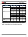
RoboClaw Electrical Specifications........................................................... 72
RoboClaw Series User Manual
4
RoboClaw Series
Brushed DC Motor Controllers
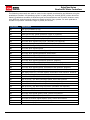
RoboClaw Revision History
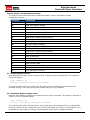
RoboClaw is an actively maintained product. New firmware features will be available from time
to time. The table below outlines key revisions that could affect the version of RoboClaw you
currently own.
Revision
Date
4.1.4
Description
1. fixed speed control using RC input(eg velocity control
using encoders with RC/Analog inputs)
2. Removes Set/GetDither commands
3. Changed PWM Duty commands to use +-15bit
values(-32768 ti 32767) for duty(-100% ti +100) and
changed duty cycle acceleration argument to use same
scaling.
4.1.3
1. USB detach/re-attach code changed
4.1.2
1. Changed battery voltages to signed calculation
2. Fixed battery cutoff settings
3. Fixed battery auto cell count detect
4. Config settings now must be saved using WriteNVM
5. USB interface is locked to packet serial mode now.
Standard serial is only available on TTL Serial pins.
6. Fixed checksum calculation on re-set encoder commands
4.1.1
1. Added timeouts on USB while loops.
2. Changed current offset calibration for better accuracy
4.1.0
1. Added new error/warning code. GetErrorStatus command
now returns 16bits of data
2. Fixed encoder re-set command to support values larger
then 65535
4.0.9
1. Removed max current error
2. Add maxcurrent chopper
3. Add temperature max current ramp down
RoboClaw Series User Manual
5
RoboClaw Series
Brushed DC Motor Controllers
Precautions
There are several important precautions that should be followed when dealing with RoboClaw or
damage will result. The following list should be observed when dealing with any motion control
systems.
1. Disconnecting the negative power terminal is not the proper way to shut down a motor
controller. If I/O are connected it can easily result in a ground loop through the attached I/O
pins. This can cause damaged to RoboClaw and or any attached devices. To shut down a motor
controller the positive power connections should be removed.
2. A DC brushed motor will work like a generator when spun. As an example a robot being
pushed or when turned off with forward momentum can create enough voltage to power
RoboClaws logic in some cases which will create an unsafe state. Always stop the motors before
powering down RoboClaw.
3. RoboClaw has minimum power requirements of at least 6V. Under heavy loads, if the logic
battery and main battery are combined, power drops can and will happen. This can cause erratic
behavior from RoboClaw.
Motor Selection
When pairing RoboClaw to a motor several key factors must be considered. All brushed DC
motors will have two amperage ratings which are maximum stall current and running current.
The most important rating is the stall current. This rating can determine what RoboClaw model
should be used.
Stall Current
A motor at rest is in a stall state. Which means during start up the motors stall current will be
reached. The loaded of the motor will determine how long maximum stall current is required.
A motor that is required to start and stop or change directions rapidly but with light load will
still require maximum stall current often. Pairing RoboClaw by using its peak current to handle
these situations is not advised. This will only result in erratic behavior and possible damage to
RoboClaw. In some applications RoboClaw can be paired using its peak current. This should only
be considered in situations where the motor is under very light load and not expect to start, stop
or change directions rapidly.
Running Current
Brushed DC motor will have two current ratings, continuous and stall ameperage. The continuous
current rating is the maximum current the motor can run at without overheating. The stall
current is the amount of amperage the motor requires on start up and likely under a heavy load
or during a high speed direction change. To properly pair a motor controller to a given brushed
DC motor you will need both of these values.
Wire Lengths
Wire lengths to the motors and from the battery should be keep as short as possible. Longer
wires will create increased inductance which will produce undesirable effects such as electrical
noise or increase ripple current. The power supply/battery wires must be as short as possible.
They should also be sized appropriately for the amout of current being drawn. Increased
inductance in the power source wires will increase the ripple current at the RoboClaw which can
damage the filter caps on the board leading to board failure.
RoboClaw Series User Manual
6
RoboClaw Series
Brushed DC Motor Controllers
Run Away
During development of your project caution should be taken to avoid run away conditions. The
wheels of a robot should not be in contact with any surface until all development is complete.
If the motor is embedded, ensure you have a safe and easy method to remove power from
RoboClaw as a fail safe.
Power Sources
A battery or linear power supply is recommended as the main power source for RoboClaw.
Switching power supplies are suitable in some cases however regeneration caused by RoboClaw
will cause most switching power supplies to behave erratically. The regeneration creates voltage
spikes because the switching power supplies are not designed to take the regenerative power.
Most switching power supply will momentarily reduce voltage and or limit current, effectively
causing brown outs which will leave RoboClaw in an unsafe state.
Optical Encoders
RoboClaw features dual channel quadrature decoding. When wiring encoders make sure the
direction of spin is correct to the motor direction. The RoboClaw internal counters increments or
decrement based on the inputs A and B. By reversing A and B signals the encoder counter will
reverse the count. Incorrect encoder connection can cause a run away state. Referring to the
encoder section of this user manual for proper setup.
RoboClaw Series User Manual
7
RoboClaw Series
Brushed DC Motor Controllers
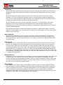
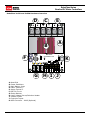
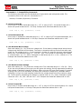
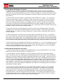
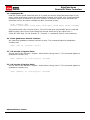
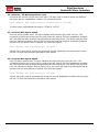
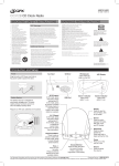
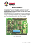
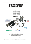
RoboClaw 2x5A Hardware Overview
D B C
+
-
M2B M2A
C28
C22
M1A M1B
U8
STAT2
ERR
C32
C23
C19
C20
A
STAT1
U4
C5
C11
CN5
H
V3
EN1
EN2
S1
S2
S3
+ + -
LB-MB
LB IN
+ -
MODE SET LIPO
E
C21
OrionRobotics.com
I
U9
RoboClaw 2x5A
C7
C9
G F
A: Power Stabilizer
B: Main Battery Input
C: Motor Channel 1
D: Motor Channel 2
E: Setup Buttons
F: Control Inputs
G: Encoder Inputs
H: Logic Voltage Source/Selection Header
I: Status and Error LED Indicators
RoboClaw Series User Manual
8
RoboClaw Series
Brushed DC Motor Controllers
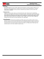
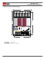
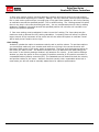
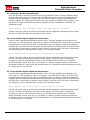
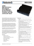
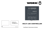
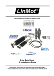
RoboClaw 2x5A Dimensions
1.7”
+
-
M2B M2A
C28
C22
M1A M1B
U8
C7
U9
C23
STAT1
STAT2
ERR
U4
C19
C11
CN5
EN1
EN2
S1
S2
S3
V3
+ + -
LB-MB
LB IN
+ -
MODE SET LIPO
C5
1.68”
C32
C20
RoboClaw 2x5A
C21
OrionRobotics.com
1.9”
C9
1.44”
Board Edge: 1.7”W X 1.9”L
Hole Pattern: 0.125D, 1.44”W x 1.68”H
RoboClaw Series User Manual
9
RoboClaw Series
Brushed DC Motor Controllers
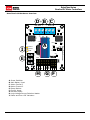
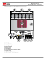
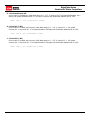
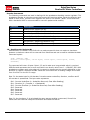
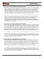
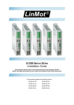
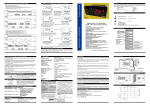
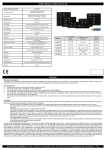
RoboClaw 2x15A and 2x30A Hardware Overview
M2B
+
-
E
M2A
C
M1B
M1A
D
A
B
RoboClaw
D3
F
K
OrionRobotics.com
D4
R7
G
V3
EN1
EN2
S1
S2
S3
+ + -
LIPO
LB-MB
SET
LB IN
MODE
CN5
+ -
ERR
STAT2
STAT1
R10
H I J
A: Heat Sink
B: Power Stabilizers
C: Main Battery Input
D: Motor Channel 1
E: Motor Channel 2
F: BEC 3A Circuit
G: Setup Buttons
H: Logic Voltage Source/Selection Header
I: Encoder Inputs
J: Controller Inputs
K: USB Connector - MiniB (Optional)
RoboClaw Series User Manual
10
RoboClaw Series
Brushed DC Motor Controllers
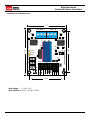
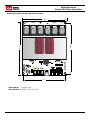
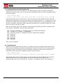
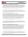
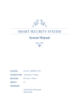
RoboClaw 2x15A and 2x30A Dimensions
2”
2.6”
2.9”
M2A
M2B
+
M1B
M1A
-
D3
RoboClaw
OrionRobotics.com
R7
V3
EN1
EN2
S1
S2
S3
+ + -
LIPO
LB-MB
SET
LB IN
MODE
CN5
+ -
ERR
STAT2
STAT1
R10
D4
1.8”
Board Edge: 2”W X 2.9”L
Hole Pattern: 0.125D, 1.8”W x 2.6”H
RoboClaw Series User Manual
11
RoboClaw Series
Brushed DC Motor Controllers
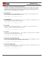
RoboClaw 2x60A and HV 2x60A Hardware Overview
C
- +
M1B
A
M1B
V4
F
K
G
+ E 1
E 2
S1
S2
S
LIPO
+ + -
SET
L -M
MODE
L
I
D3
C4
+ -
ERR
STAT2
STAT1
C3
RoboClaw 2x60A
OrionRobotics.com
M1A
B
D
M1A
E
H I J
A: Heat Sink
B: Power Stabilizers
C: Main Battery Input
D: Motor Channel 1
E: Motor Channel 2
F: BEC 3A Circuit
G: Setup Buttons
H: Logic Voltage Source/Selection Header
I: Encoder Inputs
J: Controller Inputs
K: USB Connector - MiniB (Optional)
RoboClaw Series User Manual
12
RoboClaw Series
Brushed DC Motor Controllers
RoboClaw 2x60A and HV 2x60A Dimensions
3.4”
- +
M1B
M1A
M1B
E 1
E 2
S1
S2
S
LIPO
+ + -
SET
L -M
MODE
L
I
+ -
+ -
ERR
STAT2
STAT1
D3
C4
RoboClaw 2x60A
OrionRobotics.com
3.9”
3.67”
M1A
V4
C3
3.1”
Board Edge: 3.4”W X 3.9”L
Hole Pattern: 0.125D, 3.1”W x 3.67”H
RoboClaw Series User Manual
13
RoboClaw Series
Brushed DC Motor Controllers
Header Overview
They same header layout is shared for each of the RoboClaw models covered in this user
manual. The main control I/O are arranged for easy connectivity to control devices such as
RC controllers. The headers are also arranged to provide easy access to ground and power for
supplying power to external controllers.
LB IN
LB-MB
+ + -
EN1
EN2
S1
S2
S3
Logic Battery (LB IN)
The logic side of RoboClaw can be powered from a secondary battery wired to LB IN. The
positive (+) terminal is located at the board edge and ground (-) is the inside pin closes to the
heatsink. Remove the LB-MB jumper if a secondary battery for logic will be used.
BEC Source (LB-MB)
RoboClaw logic requires 5VDC which is provided from the on board BEC circuit. The BEC source
input is set with the LB-MB jumper. Install a jumper on the 2 pins labeled LB-MB to use the main
battery as the BEC power source. Remove this jumper if using a separate logic battery.
Encoder Power (+ -)
The pins labeled + and - are the source power pins for encoders. The positive (+) is located at
the board edge and supplies +5VDC. The ground (-) pin is near the heatsink.
Encoder Inputs (EN1 / EN2)
EN1 and EN2 are the inputs from the encoders. Channel A of both EN1 and EN2 are located at
the board edge. Channel B pins are located near the heatsink. When connecting the encoder
make sure the leading channel for the direction of rotation is connected to A. If one encoder is
backwards to the other you will have one internal counter counting up and the other counting
down. Refer to the data sheet of the encoder you are using for channel direction.
Control Inputs (S1 / S2 / S3)
S1, S2 and S3 are setup for standard servo style headers I/O, +5V and GND. S1 and S2 are the
control inputs for serial, analog and RC modes. S3 can be used as a flip switch input when in
RC or Analog modes. In serial mode S3 becomes an emergency stop. S3 is active when pulled
low. It is internally pull up so it will not accidentally trip when left floating. The pins closest to
the board edge are the I/0s, center pin is the +5V and the inside pins are ground. Some RC
receivers have their own supply and will conflict with the RoboClaw’s logic supply. It may be
necessary to remove the +5V pin from the RC receivers cable in those cases.
RoboClaw Series User Manual
14
RoboClaw Series
Brushed DC Motor Controllers
Main Battery Screw Terminals
The main power input can be from 6VDC to 34VDC on a standard RoboClaw and 10.5VDC to
60VDC for the HV (High Voltage) RoboClaw. The connections are marked + and - on the main
screw terminal. + is the positive terminal and - is the negative terminal. The main battery wires
should be short as possible.
Disconnect
The main battery should have a disconnect in case of a run away situation and power needs to
be cut. The switch must be rated to handle the maximum current and voltage from the battery.
This will vary depending on the type of motors and or power source you are using. A typically
solution would be an inexpensive contactor which can be source from sites like Ebay.
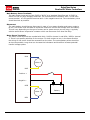
Motor Screw Terminals
The motor screw terminals are marked with M1A / M1B for channel 1 and M2A / M2B for channel
2. There is no specific polarities for the motors. For both motors to turn in the same direction
the wiring of one motor should be reversed from the other. The motor/battery wires should be
as short as possible. Long wires can increase the inductance and therefore increase potential
harmful voltage spikes.
M1A
Motor 1
M1B
Positive +
Negative
-
-
M2B
Motor 2
+
Battery
M2A
RoboClaw Series User Manual
15
RoboClaw Series
Brushed DC Motor Controllers
ERR
STAT2
STAT1
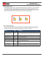
Status and Error LEDs
The RoboClaw has three LEDs. Two status LEDs marked STAT1 and STAT2. An error LED marked
ERR. When RoboClaw is first powered up all 3 LEDs should blink briefly to indicate all 3 LEDs
are functional. LEDs will behave differently depending on the mode RoboClaw is set to. During
normal operation status 1 LED will remain lite continuously or blink when data is received in RC
Mode or Serial Modes. Status 2 LED will light when the drive stage is active.
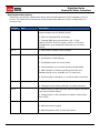
Error and Warning States
When an error occurs both motor channel outputs will be disabled and RoboClaw will stop any
further actions until the error state is cleared. When a warnings occurs both motor channel
outputs will continue to function and the RoboClaw will continue to operate.
State
Type
Description
E-Stop
Error
All three LEDs solid.
Over Temperature
Error
Error LED blinking once with one second delay. Other LEDs
off.
Driver Fault
Error
Error LED blinking once. STAT1 or STAT2 indicates channel.
Main Battery Low
Error
Error LED blinking twice.
Logic Battery High
Error
Error LED blinking three times.
Logic Battery Low
Error
Error LED blinking four times.
Main Batt Board Limit
Error
Error LED blinking five times.
Max Current
Warning
Error LED solid. STAT1 or STAT2 quick blinking indicates
channel.
Max Temperature
Warning
Error LED solid (Maximum current limit is also reduced).
Main Batt User Limit
Warning
Error LED solid.
RoboClaw Series User Manual
16
RoboClaw Series
Brushed DC Motor Controllers
RoboClaw Modes
There are 4 main modes with variations totaling 14 or 15 modes in all. Each mode enables
RoboClaw to be controlled in a very specific way. The following list explains each mode and the
ideal application.
1. RC Mode 1 & 2 - With RC mode RoboClaw can be controlled from any hobby RC radio
system. RC input mode also allows low powered microcontroller such as a Basic Stamp or Nano
to control RoboClaw. RoboClaw expects servo pulse inputs to control the direction and speed.
Very similar to how a regular servo is controlled. RC mode can use encoders.
2. Analog Mode 3 & 4 - Analog mode uses an analog signal from 0V to 5V to control the
speed and direction of each motor. RoboClaw can be controlled using a potentiometer or filtered
PWM from a microcontroller. Analog mode is ideal for interfacing RoboClaw joystick positioning
systems or other non microcontroller interfacing hardware. Analog mode can use encoders.
3. Standard Serial Mode 5 & 6 - In standard serial mode RoboClaw expects TTL level RS232 serial data to control direction and speed of each motor. Standard serial is typically used
to control RoboClaw from a microcontroller or PC. If using a PC a MAX232 type circuit must be
used since RoboClaw only works with TTL level input. Standard serial includes a slave select
mode which allows multiple RoboClaws to be controlled from a signal RS-232 port (PC or
microcontroller). Standard serial is a one way format, RoboClaw only receives data.
4. Packet Serial Mode 7 through 14 - In packet serial mode RoboClaw expects TTL level
RS-232 serial data to control direction and speed of each motor. Packet serial is typically used
to control RoboClaw from a microcontroller or PC. If using a PC a MAX232 type circuit must be
used since RoboClaw only works with TTL level input. In packet serial mode each RoboClaw is
assigned an address using the dip switches. There are 8 addresses available. This means up
to 8 RoboClaws can be on the same serial port. When using the quadrature decoding feature
of RoboClaw packet serial is required since it is a two way communications format. This allows
RoboClaw to transmit information about the encoders position and speed.
5. USB Mode 15 - In USB mode the RoboClaw’s USB port acts as a CDC Virtual Comport in
Packet Serial mode with packet address 128. There are two ways to activate the USB mode.
Power up a USB RoboClaw while it is attached to an active USB cable, or set it to mode 15. If the
USB host connected to RoboClaw will be powered up at the same time as RoboClaw, mode 15
should be set.
RoboClaw Series User Manual
17
RoboClaw Series
Brushed DC Motor Controllers
Configuring RoboClaw Modes
The 3 buttons on RoboClaw are used to set the different configuration options. The MODE button
sets the interface method such as Serial or RC modes. The SET button is used to configure the
options for the mode. The LIPO button doubles as a save button and configuring the low battery
voltage cut out function of RoboClaw. To set the desired mode follow the steps below:
1. Press and release the MODE button to enter mode setup. The STAT2 LED will begin to blink
out the current mode. Each blink is a half second with a long pause at the end of the count. Five
blinks with a long pause equals mode 5 and so on.
2. Press SET to increment to the next mode. Press MODE to decrement to the previous mode.
3. Press and release the LIPO button to save this mode to memory.
MODE
SET
LIPO
Modes
Mode
Description
1
RC mode
2
RC mode with mixing
3
Analog mode
4
Analog mode with mixing
5
Standard Serial
6
Standard Serial with slave pin
7
Packet Serial Mode - Address 0x80
8
Packet Serial Mode - Address 0x81
9
Packet Serial Mode - Address 0x82
10
Packet Serial Mode - Address 0x83
11
Packet Serial Mode - Address 0x84
12
Packet Serial Mode - Address 0x85
13
Packet Serial Mode - Address 0x86
14
Packet Serial Mode - Address 0x87
15
USB Mode Packet Serial - Address 0x80
RoboClaw Series User Manual
18
RoboClaw Series
Brushed DC Motor Controllers
Mode Options
After the desired mode is set and saved press and release the SET button for options setup. The
STAT2 LED will begin to blink out the current option. Press SET to increment to the next option.
Press MODE to decrement to the previous option. Once the desired option is selected press and
release the LIPO button to save the option to memory.
RC and Analog Mode Options
Option
Description
1
TTL Flip Switch
2
TTL Flip and Exponential Enabled
3
TTL Flip and MCU Enabled
4
TTL Flip and Exp and MCU Enabled
5
RC Flip Switch
6
RC Flip and Exponential Enabled
7
RC Flip and MCU Enabled
8
RC Flip and Exponential and MCU Enabled
Standard Serial and Packet Serial Mode Options
Option
Description
1
2400bps
2
9600bps
3
19200bps
4
38400bps
Battery Cut Off Settings
The battery settings can be set by pressing and releasing the LIPO button. The STAT2 LED will
begin to blink out the current setting. Press SET to increment to the next setting. Press MODE
to decrement to the previous setting. Once the desired setting is selected press and release the
LIPO button to save this setting to memory.
Battery Options
Option
Description
1
Disabled
2
Auto Detect
3
2 Cell(6v Cutoff)
4
3 Cell(9v Cutoff)
5
4 Cell(12v Cutoff)
6
5 Cell(15v Cutoff)
7
6 Cell(18v Cutoff)
8
7 Cell(21v Cutoff)
RoboClaw Series User Manual
19
RoboClaw Series
Brushed DC Motor Controllers
USB CONTROL
RoboClaw Series User Manual
20
RoboClaw Series
Brushed DC Motor Controllers
USB RoboClaw Power
The USB RoboClaw is self powered. Which means it is not powered from the USB cable. The USB
RoboClaw must be externally powered to function correctly.
USB RoboClaw Connection
The USB RoboClaw should have its USB cable connected before powering it up unless USB mode
is specifically set (mode 15). If the master controller (the PC) is powered up the USB RoboClaw
will automatically detect it is connected to a powered USB master and will enter USB mode. In
some cases it may be necessairy to set USB mode manually by setting RoboClaw to mode 15.
USB Comport and baudrate
The USB RoboClaw will be detected as a CDC Virtual Comport. When connected to a Windows
PC a driver must be installed. The driver is available for download. On Linux or OSX the
RoboClaw will be automatically detected as a virtual comport and an appropriate driver will
automatically be loaded.
Unlike a real Comport the USB CDC Virtual Comport does not need a baud rate to be set. It
will always communicate at the fastest speed the master and slave device can reach. This will
typically be 1mbit/s.
RoboClaw Series User Manual
21
RoboClaw Series
Brushed DC Motor Controllers
RC MODE
RoboClaw Series User Manual
22
RoboClaw Series
Brushed DC Motor Controllers
RC Mode
RC mode is typically used when controlling RoboClaw from a hobby RC radio. This mode can also
be used to simplify driving RoboClaw from a microcontroller using servo pulses. In this mode S1
controls the direction and speed of motor 1 and S2 controls the speed and direction of motor 2.
This drive method is similar to how a tank is controlled.
Using RC Mode with feedback for velocity/position control
RC Mode can be used with encoders. Use IonMotion control software to enable encoders for
RC/Analog modes in General Settings. Packet Serial commands can also be used to enable this
option. Velocity and/or Position PID constants must be calibrated for proper operation. Once
calibrated values have been set and saved into Roboclaws eeprom, encoder support using
velocity or position PID control can be enabled.
RC Mode With Mixing
This mode is the same as RC mode with the exception of how S1 and S2 control the attached
motors. S1 controls speed and direction of both motors 1 and 2. S2 controls steering by slowing
one of the motors. This drive method is similar to how a car would be controlled.
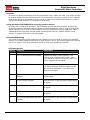
RC Mode Options
Option
Function
Description
1
TTL Flip Switch
Flip switch triggered by low signal.
2
TTL Flip and Exponential Enabled
Softens the center control position. This
mode is ideal with tank style robots. Making it easier to control from an RC radio. Flip
switch triggered by low signal.
3
TTL Flip and MCU Enabled
Continues to execute last pulse received until
new pulse received. Disables Signal loss fail
safe and auto calibration. Flip switch triggered by low signal.
4
TTL Flip and Exponential and MCU
Enabled
Enables both options. Flip switch triggered
by low signal.
5
RC Flip Switch Enabled
Same as mode 1 with flip switch triggered by
RC signal.
6
RC Flip and Exponential Enabled
Same as mode 2 with flip switch triggered by
RC signal.
7
RC Flip and MCU Enabled
Same as mode 3 with flip switch triggered by
RC signal.
8
RC Flip and Exponential and MCU
Enabled
Same as mode 4 with flip switch triggered by
RC signal.
RoboClaw Series User Manual
23
RoboClaw Series
Brushed DC Motor Controllers
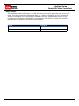
Pulse Ranges
The RoboClaw expects RC pulses on S1 and S2 to drive the motors when the mode is set to RC
mode. The center points are calibrated at start up. 1000us is the default for full reverse and
2000us is the default for full forward. The RoboClaw will auto calibrate these ranges on the
fly unless auto-calibration is disabled. If a pulse smaller than 1000us or larger than 2000us is
detected the new pulses will be set as the new ranges.
Pulse
Function
1000us
Full Reverse
2000us
Full Forward
RoboClaw Series User Manual
24
RoboClaw Series
Brushed DC Motor Controllers
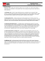
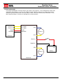
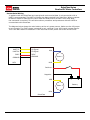
RC Wiring Example
Connect the RoboClaw as shown below. Set mode 1 with option 1. The configuration below uses
a separate logic battery so remove the MB-LB jumper. Before powering up, center the control
sticks on the radio transmitter, turn the radio on first, then the receiver, then RoboClaw. It will
take RoboClaw about 1 second to calibrate the neutral position.
Channel 1
S1 Signal
Channel 2
S2 Signal
5VDC
GROUND
M1A
5VDC
Motor 1
GROUND
M1B
Receiver
Positive +
Negative
-
-
M2B
Motor 2
+
Battery
M2A
RoboClaw
RoboClaw Series User Manual
25
RoboClaw Series
Brushed DC Motor Controllers
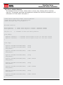
RC Control - Arduino Example
The example will drive a 2 motor 4 wheel robot in reverse, stop, forward, left turn and then
right turn. The program was written and tested with a Arduino Uno and P5 connected to S1, P6
connected to S2. Set mode 2 with option 4.
//Basic Micro RoboClaw RC Mode. Control RoboClaw
//with servo pulses from a microcontroller.
//Mode settings: Mode 2 with Option 4.
#include <Servo.h>
Servo myservo1;
Servo myservo2;
int pos = 0;
// create servo object to control a RoboClaw channel
// create servo object to control a RoboClaw channel
// variable to store the servo position
void setup()
{
myservo1.attach(5);
myservo2.attach(6);
}
// attaches the RC signal on pin 5 to the servo object
// attaches the RC signal on pin 6 to the servo object
void loop()
{
myservo1.writeMicroseconds(1500);
myservo2.writeMicroseconds(1500);
delay(2000);
}
//Stop
//Stop
myservo1.writeMicroseconds(1250);
delay(1000);
//full forward
myservo1.writeMicroseconds(1500);
delay(2000);
//stop
myservo1.writeMicroseconds(1750);
delay(1000);
//full reverse
myservo1.writeMicroseconds(1500);
delay(2000);
//Stop
myservo2.writeMicroseconds(1250);
delay(1000);
//full forward
myservo2.writeMicroseconds(1500);
delay(2000);
//Stop
myservo2.writeMicroseconds(1750);
delay(1000);
//full reverse
RoboClaw Series User Manual
26
RoboClaw Series
Brushed DC Motor Controllers
ANALOG MODE
RoboClaw Series User Manual
27
RoboClaw Series
Brushed DC Motor Controllers
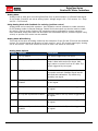
Analog Mode
Analog mode is used when controlling RoboClaw from a potentiometer or a filtered PWM signal.
In this mode S1 and S2 are set as analog inputs. Voltage range is 0V = Full reverse, 1V = Stop
and 2V = Full forward.
Using Analog Mode with feedback for velocity/position control
Analog Mode can be used with encoders. Use IonMotion control software to enable encoders
for RC/Analog modes in General Settings. Packet Serial commands can also be used to enable
this option. Velocity and/or Position PID constants must be calibrated for proper operation.
Once calibrated values have been set and saved into Roboclaws eeprom, encoder support using
velocity or position PID control can be enabled.
Analog Mode With Mixing
This mode is the same as Analog mode with the exception of how S1 and S2 control the attached
motors. S1 controls speed and direction of both motors 1 and 2. S2 controls steering by slowing
one of the motors. This drive method is similar to how a car would be controlled.
Analog Mode Options
Option
Function
Description
1
TTL Flip Switch
Flip switch triggered by low signal.
2
TTL Flip and Exponential Enabled
Softens the center control position. This
mode is ideal with tank style robots. Making it easier to control from an RC radio. Flip
switch triggered by low signal.
3
TTL FLip and MCU Enabled
Continues to execute last pulse received until
new pulse received. Disables Signal loss fail
safe and auto calibration. Flip switch triggered by low signal.
4
TTL FLip and Exponential and MCU Enables both options. Flip switch triggered
Enabled
by low signal.
5
RC Flip Switch Enabled
Same as mode 1 with flip switch triggered by
RC signal.
6
RC Flip and Exponential Enabled
Same as mode 2 with flip switch triggered by
RC signal.
7
RC Flip and MCU Enabled
Same as mode 3 with flip switch triggered by
RC signal.
8
RC Flip and Exponential and MCU
Enabled
Same as mode 4 with flip switch triggered by
RC signal.
RoboClaw Series User Manual
28
RoboClaw Series
Brushed DC Motor Controllers
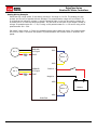
Analog Wiring Example
RoboClaw use a high speed 12 bit analog converter. Its range is 0 to 2V. The analog pins are
protect and 5V can be applied without damage. The potentiometer range will be limited if 5V
is utilized as the reference voltage. A simple resistor divider circuit can be used to reduce the
on board 5V to 2V. See the below schematic. The POT acts as one half of the resistor divider. If
using a 5k potentiometer R1 = 7.5k, If using a 10k potentiometer R1 = 15k and if using a 20k
potentiometer R1 = 30k.
Set mode 3 with option 1. Center the potentiometers before applying power. S1 potentiometer
will control motor 1 direction and speed. S2 potentiometer will control motor 2 direction and
speed.
GROUND
S1 Signal
Pot 1
R1
M1A
5VDC
Motor 1
M1B
GROUND
S2 Signal
Pot 2
R1
Positive +
5VDC
Negative
-
-
M2B
Motor 2
+
Battery
M2A
RoboClaw
RoboClaw Series User Manual
29
RoboClaw Series
Brushed DC Motor Controllers
STANDARD SERIAL
RoboClaw Series User Manual
30
RoboClaw Series
Brushed DC Motor Controllers
Standard Serial Mode
In this mode S1 accepts TTL level byte commands. Standard serial mode is one way serial data.
RoboClaw can receive only. A standard 8N1 format is used. Which is 8 bits, no parity bits and
1 stop bit. If you are using a microcontroller you can interface directly to RoboClaw. If you are
using a PC a level shifting circuit (See Max232) is required. The baud rate can be changed using
the SET button once a serial mode has been selected.
Serial Mode Baud Rates
Option
Description
1
2400
2
9600
3
19200
4
38400
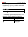
Standard Serial Command Syntax
The RoboClaw standard serial is setup to control both motors with one byte sized command
character. Since a byte can be anything from 0 to 255 the control of each motor is split. 1 to 127
controls channel 1 and 128 to 255 controls channel 2. Command character 0 will shut down both
channels. Any other values will control speed and direction of the specific channel.
Character
Function
0
Shuts Down Channel 1 and 2
1
Channel 1 - Full Reverse
64
Channel 1 - Stop
127
Channel 1 - Full Forward
128
Channel 2 - Full Reverse
192
Channel 2 - Stop
255
Channel 2 - Full Forward
RoboClaw Series User Manual
31
RoboClaw Series
Brushed DC Motor Controllers
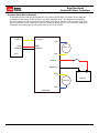
Standard Serial Wiring Example
In standard serial mode the RoboClaw can only receive serial data. The below wiring diagram
illustrates a basic setup of RoboClaw for use with standard serial. The diagram below shows
the main battery as the only power source. Make sure the LB jumper is set correctly. The 5VDC
shown connected is only required if your MCU needs a power source. This is the BEC feature of
RoboClaw. If the MCU has its own power source do not the 5VDC.
UART TX
5VDC
GROUND
S1 Signal
M1A
5VDC
Motor 1
GROUND
M1B
MCU
Positive +
Negative
-
-
M2B
Motor 2
+
Battery
M2A
RoboClaw
RoboClaw Series User Manual
32
RoboClaw Series
Brushed DC Motor Controllers
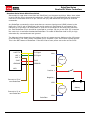
Standard Serial Mode With Slave Select
Slave select is used when more than one RoboClaw is on the same serial bus. When slave select
is set to ON the S2 pin becomes the select pin. Set S2 high (5V) and RoboClaw will execute the
next set of commands sent to S1 pin. Set S2 low (0V) and RoboClaw will ignore all received
commands.
Any RoboClaw connected to a bus must share a common signal ground (GND) shown by the
black wire. The S1 pin of RoboClaw is the serial receive pin and should be connected to the
transmit pin of the MCU. All RoboClaw’s S1 pins will be connected to the same MCU transmit
pin. Each RoboClaw S2 pin should be connected to a unique I/O pin on the MCU. S2 is used as
the control pin to activate the attached RoboClaw. To enable a RoboClaw hold its S2 pin high
otherwise any commands sent are ignored.
The diagram below shows the main battery as the only power source. Make sure the LB jumper
is set correctly. The 5VDC shown connected is only required if your MCU needs a power source.
This is the BEC feature of RoboClaw. If the MCU has its own power source do not the 5VDC.
UART TX
S1 Signal
OUT 1
S2 Signal
M1A
OUT 2
5VDC
GROUND
Motor 1
5VDC
GROUND
M1B
MCU
Positive +
Negative
Connect to S2 of
next RoboClaw
-
-
M2B
Motor 2
Connect to S1 of
next RoboClaw
+
Battery
M2A
RoboClaw
RoboClaw Series User Manual
33
RoboClaw Series
Brushed DC Motor Controllers
Standard Serial - Arduino Example
The following example will start both channels in reverse, then full speed forward. The program
was written and tested with a Arduino Uno and Pin 5 connected to S1. Set mode 5 and option 3.
//RoboClaw Standard Serial Test
//Switch settings: SW2=ON and SW5=ON
//Make sure Arduino and Robo Claw share common GND!
#include “BMSerial.h”
BMSerial mySerial(5,6);
void setup() {
mySerial.begin(19200);
}
void loop() {
mySerial.write(1);
mySerial.write(-1);
delay(2000);
mySerial.write(127);
mySerial.write(-127);
delay(2000);
}
RoboClaw Series User Manual
34
RoboClaw Series
Brushed DC Motor Controllers
PACKET SERIAL
RoboClaw Series User Manual
35
RoboClaw Series
Brushed DC Motor Controllers
Packet Serial Mode
Packet serial is a buffered bidirectional serial mode. More sophisticated instructions can be sent
to RoboClaw. The basic command structures consists of an address byte, command byte, data
bytes and a checksum. The amount of data each command will send or receive can vary.
Address
Packet serial requires a unique address. With up to 8 addresses available you can have up to 8
RoboClaws bussed on the same RS232 port. There are 8 packet modes 7 to 14. Each mode has
a unique address. The address is selected by setting the desired packet mode using the MODE
button.
Packet Modes
Mode
Description
7
Packet Serial Mode - Address 0x80 (128)
8
Packet Serial Mode - Address 0x81 (129)
9
Packet Serial Mode - Address 0x82 (130)
10
Packet Serial Mode - Address 0x83 (131)
11
Packet Serial Mode - Address 0x84 (132)
12
Packet Serial Mode - Address 0x85 (133)
13
Packet Serial Mode - Address 0x86 (134)
14
Packet Serial Mode - Address 0x87 (135)
Packet Serial Baud Rate
When in serial mode or packet serial mode the baud rate can be changed to one of four different
settings in the table below. These are set using the SET button as covered in Mode Options.
Serial Mode Options
Option
Description
1
2400
2
9600
3
19200
4
38400
RoboClaw Series User Manual
36
RoboClaw Series
Brushed DC Motor Controllers
Checksum Calculation
All packet serial commands use a 7 bit checksum to prevent corrupt commands from being
executed. Since the RoboClaw expects a 7bit value the 8th bit is masked. The checksum is
calculated as follows:
Checksum = (Address + Command + Data bytes) & 0x7F
When calculating the checksum all data bytes sent or received must be added together. The
hexadecimal value 0X7F is used to mask the 8th bit.
Packet Timeout
When sending a packet to RoboClaw, if there is a delay longer than 10ms between bytes being
received in a packet, RoboClaw will discard the entire packet. This will allow the packet buffer to
be cleared by simply adding a minimum 10ms delay before sending a new packet command.
Packet Acknowledgement
If you set the 8th bit of the checksum byte to one RoboClaw will send an acknowledgment byte
back on write only packet commands that were properly received and were valid commands.
Checksum = (Address + Command + Data bytes) & 0x7F | 0x80
The value sent back is 0xFF. if the packet was not valid for any reason no acknowledgement will
be sent back.
RoboClaw Series User Manual
37
RoboClaw Series
Brushed DC Motor Controllers
Commands 0 - 7 Compatibility Commands
The following commands are the standard set of commands used with packet mode. The
command syntax is the same for commands 0 to 7:
Address, Command, ByteValue, Checksum
0 - Drive Forward M1
Drive motor 1 forward. Valid data range is 0 - 127. A value of 127 = full speed forward, 64 =
about half speed forward and 0 = full stop. Example with RoboClaw address set to 128:
Send: 128, 0, 127, ((128+0+127) & 0X7F)
1 - Drive Backwards M1
Drive motor 1 backwards. Valid data range is 0 - 127. A value of 127 full speed backwards, 64 =
about half speed backward and 0 = full stop. Example with RoboClaw address set to 128:
Send: 128, 1, 127, ((128+0+127) & 0X7F)
2 - Set Minimum Main Voltage
Sets main battery (B- / B+) minimum voltage level. If the battery voltages drops below the set
voltage level RoboClaw will shut down. The value is cleared at start up and must set after each
power up. The voltage is set in .2 volt increments. A value of 0 sets the minimum value allowed
which is 6V. The valid data range is 0 - 120 (6V - 30V). The formula for calculating the voltage
is: (Desired Volts - 6) x 5 = Value. Examples of valid values are 6V = 0, 8V = 10 and 11V = 25.
Example with RoboClaw address set to 128:
Send: 128, 2, 25, ((128+2+25) & 0X7F)
3 - Set Maximum Main Voltage
Sets main battery (B- / B+) maximum voltage level. The valid data range is 0 - 154 (0V - 30V).
If you are using a battery of any type you can ignore this setting. During regenerative breaking a
back voltage is applied to charge the battery. When using an ATX type power supply if it senses
anything over 16V it will shut down. By setting the maximum voltage level, RoboClaw before
exceeding it will go into hard breaking mode until the voltage drops below the maximum value
set. The formula for calculating the voltage is: Desired Volts x 5.12 = Value. Examples of valid
values are 12V = 62, 16V = 82 and 24V = 123. Example with RoboClaw address set to 128:
Send: 128, 3, 82, ((128+3+82) & 0X7F)
4 - Drive Forward M2
Drive motor 2 forward. Valid data range is 0 - 127. A value of 127 full speed forward, 64 = about
half speed forward and 0 = full stop. Example with RoboClaw address set to 128:
Send: 128, 4, 127, ((128+4+127) & 0X7F)]
RoboClaw Series User Manual
38
RoboClaw Series
Brushed DC Motor Controllers
5 - Drive Backwards M2
Drive motor 2 backwards. Valid data range is 0 - 127. A value of 127 full speed backwards, 64 =
about half speed backward and 0 = full stop. Example with RoboClaw address set to 128:
Send: 128, 5, 127, ((128+5+127) & 0X7F)
6 - Drive M1 (7 Bit)
Drive motor 1 forward and reverse. Valid data range is 0 - 127. A value of 0 = full speed
reverse, 64 = stop and 127 = full speed forward. Example with RoboClaw address set to 128:
Send: 128, 6, 96, ((128+6+96) & 0X7F)
7 - Drive M2 (7 Bit)
Drive motor 2 forward and reverse. Valid data range is 0 - 127. A value of 0 = full speed
reverse, 64 = stop and 127 = full speed forward. Example with RoboClaw address set to 128:
Send: 128, 7, 32, ((128+7+32) & 0X7F)
RoboClaw Series User Manual
39
RoboClaw Series
Brushed DC Motor Controllers
Commands 8 - 13 Mix Mode Compatibility Commands
The following commands are mix mode commands and used to control speed and turn. Before
a command is executed valid drive and turn data is required. You only need to send both data
packets once. After receiving both valid drive and turn data RoboClaw will begin to operate. At
this point you only need to update turn or drive data.
8 - Drive Forward
Drive forward in mix mode. Valid data range is 0 - 127. A value of 0 = full stop and 127 = full
forward. Example with RoboClaw address set to 128:
Send: 128, 8, 127, ((128+8+127) & 0x7F)
9 - Drive Backwards
Drive backwards in mix mode. Valid data range is 0 - 127. A value of 0 = full stop and 127 = full
reverse. Example with RoboClaw address set to 128:
Send: 128, 9, 127, ((128+9+127) & 0x7F)
10 - Turn right
Turn right in mix mode. Valid data range is 0 - 127. A value of 0 = stop turn and 127 = full
speed turn. Example with RoboClaw address set to 128:
Send: 128, 10, 127, ((128+10+127) & 0x7F1)
11 - Turn left
Turn left in mix mode. Valid data range is 0 - 127. A value of 0 = stop turn and 127 = full speed
turn. Example with RoboClaw address set to 128:
Send: 128, 11, 127, ((128+11+127) & 0x7F)
12 - Drive Forward or Backward (7 Bit)
Drive forward or backwards. Valid data range is 0 - 127. A value of 0 = full backward, 64 = stop
and 127 = full forward. Example with RoboClaw address set to 128:
Send: 128, 12, 96, ((128+12=96) & 0x7F)
13 - Turn Left or Right (7 Bit)
Turn left or right. Valid data range is 0 - 127. A value of 0 = full left, 0 = stop turn and 127 = full
right. Example with RoboClaw address set to 128:
Send: 128, 13, 0, ((128+13=0) & 0x7F)
RoboClaw Series User Manual
40
RoboClaw Series
Brushed DC Motor Controllers
Packet Serial Wiring
In packet mode the RoboClaw can transmit and receive serial data. A microcontroller with a
UART is recommended. The UART will buffer the data received from RoboClaw. When a request
for data is made to RoboClaw the return data will always have at least a 1ms delay after
the command is received. This will allow slower processors and processors without UARTs to
communicate with RoboClaw.
The diagram below shows the main battery as the only power source. Make sure the LB jumper
is set correctly. The 5VDC shown connected is only required if your MCU needs a power source.
This is the BEC feature of RoboClaw. If the MCU has its own power source do not the 5VDC.
UART TX
S1 Signal
UART RX
S2 Signal
5VDC
GROUND
M1A
5VDC
Motor 1
GROUND
M1B
MCU
Positive +
Negative
-
-
M2B
Motor 2
+
Battery
M2A
RoboClaw
RoboClaw Series User Manual
41
RoboClaw Series
Brushed DC Motor Controllers
Packet Serial - Arduino Example
The example will start the motor channels independently. Then start turns with mix mode
commands. The program was written and tested with a Arduno Uno and P5 connected to S1. Set
mode 7 and option 3.
//RoboClaw Packet Serial Test Commands 0 to 13.
//Switch settings: SW3=ON and SW5=ON.
#include “BMSerial.h”
#include “RoboClaw.h”
#define address 0x80
RoboClaw roboclaw(5,6,10000);
void setup() {
roboclaw.begin(19200);
}
void loop() {
roboclaw.ForwardM1(address,64); //Cmd 0
roboclaw.BackwardM2(address,64);//Cmd 5
delay(2000);
roboclaw.BackwardM1(address,64);//Cmd 1
roboclaw.ForwardM2(address,64); //Cmd 6
delay(2000);
roboclaw.ForwardBackwardM1(address,96);
//Cmd
roboclaw.ForwardBackwardM2(address,32);
//Cmd
delay(2000);
roboclaw.ForwardBackwardM1(address,32);
//Cmd
roboclaw.ForwardBackwardM2(address,96);
//Cmd
delay(2000);
6
7
6
7
//stop motors
roboclaw.ForwardBackwardM1(address,0);
roboclaw.ForwardBackwardM2(address,0);
delay(10000);
roboclaw.ForwardMixed(address, 64);
//Cmd
delay(2000);
roboclaw.BackwardMixed(address, 64); //Cmd
delay(2000);
roboclaw.TurnRightMixed(address, 64); //Cmd
delay(2000);
roboclaw.TurnLeftMixed(address, 64);
delay(2000);
roboclaw.ForwardBackwardMixed(address, 32);
delay(2000);
roboclaw.ForwardBackwardMixed(address, 96);
delay(2000);
roboclaw.LeftRightMixed(address, 32); //Cmd
delay(2000);
roboclaw.LeftRightMixed(address, 96); //Cmd
delay(2000);
8
9
10
//Cmd 11
//Cmd 12
//Cmd 12
13
13
//stop motors
roboclaw.ForwardMixed(address, 0);
}
delay(10000);
RoboClaw Series User Manual
42
RoboClaw Series
Brushed DC Motor Controllers
ADVANCED
PACKET SERIAL
RoboClaw Series User Manual
43
RoboClaw Series
Brushed DC Motor Controllers
Version, Status, and Settings Commands
The following commands are used to read board status, version information and set
configuration values.
Command
Description
21
Read Firmware Version
24
Read Main Battery Voltage
25
Read Logic Battery Voltage
26
Set Minimum Logic Voltage Level
27
Set Maximum Logic Voltage Level
49
Read Motor Currents
55
Read Motor 1 Velocity PID Constants
56
Read Motor 2 Velocity PID Constants
57
Set Main Battery Voltages
58
Set Logic Battery Voltages
59
Read Main Battery Voltage Settings
60
Read Logic Battery Voltage Settings
63
Read Motor 1 Position PID Constants
64
Read Motor 2 Position PID Constants
82
Read Temperature
83
Read Temperature 2
90
Read Error Status
91
Read Encoder Mode
92
Set Motor 1 Encoder Mode
93
Set Motor 2 Encoder Mode
94
Write Settings to EEPROM
21 - Read Firmware Version
Read RoboClaw firmware version. Returns up to 32 bytes and is terminated by a null character.
Command syntax:
Send: [Address, 21]
Receive: [“RoboClaw 10.2A v1.3.9, Checksum]
The command will return up to 32 bytes. The return string includes the product name and
firmware version. The return string is terminated with a null (0) character.
24 - Read Main Battery Voltage Level
Read the main battery voltage level connected to B+ and B- terminals. The voltage is returned in
10ths of a volt. Command syntax:
Send: [Address, 24]
Receive: [Value.Byte1, Value.Byte0, Checksum]
The command will return 3 bytes. Byte 1 and 2 make up a word variable which is received MSB
first and is 10th of a volt. A returned value of 300 would equal 30V. Byte 3 is the checksum. It is
calculated the same way as sending a command and can be used to validate the data.
RoboClaw Series User Manual
44
RoboClaw Series
Brushed DC Motor Controllers
25 - Read Logic Battery Voltage Level
Read a logic battery voltage level connected to LB+ and LB- terminals. The voltage is returned
in 10ths of a volt. Command syntax:
Send: [Address, 25]
Receive: [Value.Byte1, Value.Byte0, Checksum]
The command will return 3 bytes. Byte 1 and 2 make up a word variable which is received MSB
first and is 10th of a volt. A returned value of 50 would equal 5V. Byte 3 is the checksum. It is
calculated the same way as sending a command and can be used to validate the data.
26 - Set Minimum Logic Voltage Level
Sets logic input (LB- / LB+) minimum voltage level. If the battery voltages drops below the set
voltage level RoboClaw will shut down. The value is cleared at start up and must set after each
power up. The voltage is set in .2 volt increments. A value of 0 sets the minimum value allowed
which is 3V. The valid data range is 0 - 120 (6V - 28V). The formula for calculating the voltage
is: (Desired Volts - 6) x 5 = Value. Examples of valid values are 3V = 0, 8V = 10 and 11V = 25.
Send: [128, 26, 0, (154 & 0X7F)]
27 - Set Maximum Logic Voltage Level
Sets logic input (LB- / LB+) maximum voltage level. The valid data range is 0 - 144 (0V - 28V).
By setting the maximum voltage level RoboClaw will go into shut down and requires a hard reset
to recovers. The formula for calculating the voltage is: Desired Volts x 5.12 = Value. Examples
of valid values are 12V = 62, 16V = 82 and 24V = 123.
Send: [128, 27, 82, (213 & 0X7F)]
49 - Read Motor Currents
Read the current draw from each motor in 10ma increments. Command syntax:
Send: [Address, 49]
Receive: [M1Cur.Byte1, M1Cur.Byte0, M2Cur.Byte1, M2Cur.Byte0, Checksum]
The command will return 5 bytes. Bytes 1 and 2 combine to represent the current in 10ma
increments of motor1. Bytes 3 and 4 combine to represent the current in 10ma increments of
motor2 . Byte 5 is the checksum.
55 - Read Motor 1 P, I, D and QPPS Settings
Read the PID and QPPS Settings. Command syntax:
Send: [Address, 55]
Receive: [P(4 bytes), I(4 bytes), D(4 bytes), QPPS(4 byte), Checksum]
56 - Read Motor 2 P, I, D and QPPS Settings
Read the PID and QPPS Settings. Command syntax:
Send: [Address, 56]
Receive: [P(4 bytes), I(4 bytes), D(4 bytes), QPPS(4 byte), Checksum]
RoboClaw Series User Manual
45
RoboClaw Series
Brushed DC Motor Controllers
57 - Set Main Battery Voltages
Set the Main Battery Voltages cutoffs, Min and Max. Command syntax:
Send: [Address, 57, Min(2 bytes), Max(2bytes, Checksum]
58 - Set Logic Battery Voltages
Set the Logic Battery Voltages cutoffs, Min and Max. Command syntax:
Send: [Address, 58, Min(2 bytes), Max(2bytes, Checksum]
59 - Read Main Battery Voltage Settings
Read the Main Battery Voltage Settings. Command syntax:
Send: [Address, 59]
Receive: [Min(2 bytes), Max(2 bytes), Checksum]
60 - Read Logic Battery Voltage Settings
Read the Main Battery Voltage Settings. Command syntax:
Send: [Address, 60]
Receive: [Min(2 bytes), Max(2 bytes), Checksum]
63 - Read Motor 1 Position P, I, D Constants
Read the Position PID Settings. Command syntax:
Send: [Address, 63]
Receive: [P(4 bytes), I(4 bytes), D(4 bytes), MaxI(4 byte), Deadzone(4 byte),
MinPos(4 byte), MaxPos(4 byte), Checksum]
64 - Read Motor 2 Position P, I, D Constants
Read the Position PID Settings. Command syntax:
Send: [Address, 64]
Receive: [P(4 bytes), I(4 bytes), D(4 bytes), MaxI(4 byte), Deadzone(4 byte),
MinPos(4 byte), MaxPos(4 byte), Checksum]
82 - Read Temperature
Read the board temperature. Value returned is in 0.1 degree increments. Command syntax:
Send: [Address, 82]
Receive: [Temperature(2 bytes), Checksum]
83 - Read Temperature 2
Read the second board temperature(on supported units). Value returned is in 0.1 degree
increments. Command syntax:
Send: [Address, 83]
Receive: [Temperature(2 bytes), Checksum]
RoboClaw Series User Manual
46
RoboClaw Series
Brushed DC Motor Controllers
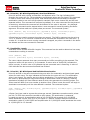
90 - Read Error Status
Read the current error status. Command syntax:
Send: [Address, 90]
Receive: [Error, Checksum]
Error Mask
Normal
0x00
M1 OverCurrent
0x01
M2 OverCurrent
0x02
E-Stop0x04
Temperature
0x08
Main Battery High 0x10
Main Battery Low
0x20
Logic Battery High 0x40
Logic Battery Low 0x80
91 - Read Encoder Mode
Read the encoder mode for both motors. Command syntax:
Send: [Address, 91]
Receive: [Mode1, Mode2, Checksum]
92 - Set Motor 1 Encoder Mode
Set the Encoder Mode for motor 1. Command syntax:
Send: [Address, 92, Mode, Checksum]
93 - Set Motor 2 Encoder Mode
Set the Encoder Mode for motor 1. Command syntax:
Send: [Address, 93, Mode, Checksum]
Encoder Mode bits
Bit 7 Enable RC/Analog Encoder support
Bit 6-1N/A
Bit 0 Quadrature(0)/Absolute(1)
94 - Write Settings to EEPROM
Writes all settings to non-volatile memory. Command syntax:
Send: [Address, 94]
Receive: [Checksum]
RoboClaw Series User Manual
47
RoboClaw Series
Brushed DC Motor Controllers
ENCODERS
RoboClaw Series User Manual
48
RoboClaw Series
Brushed DC Motor Controllers
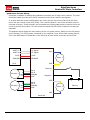
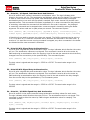
Quadrature Encoder Wiring
RoboClaw is capable of reading two quadrature encoders one for each motor channel. The main
RoboClaw header provides two +5VDC connections with dual A and B input signals.
In a robot with two motors configuration one motor will spin clock wise (CW) while the other
motor will spin counter clock wise (CCW). The A and B inputs for one of the encoders must be
reversed as shown. If both encoder are connected with leading edge pulse to channel A one will
count up and the other down. This will cause commands like Mix Drive Forward to not work as
expected.
The diagram below shows the main battery as the only power source. Make sure the LB jumper
is set correctly. The 5VDC shown connected is only required if your MCU needs a power source.
This is the BEC feature of RoboClaw. If the MCU has its own power source do not the 5VDC.
UART TX
S1 Signal
UART RX
S2 Signal
M1A
5VDC
5VDC
Motor 1
GROUND
GROUND
M1B
MCU
Encoder 1
A
B
GND
+5V
EN1 A
EN1 B
GROUND
5VDC
Encoder 2
A
B
GND
+5V
EN2 B
EN2 A
GROUND
5VDC
Positive +
Negative
-
-
M2B
Motor 2
+
Battery
M2A
RoboClaw
RoboClaw Series User Manual
49
RoboClaw Series
Brushed DC Motor Controllers
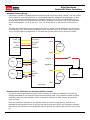
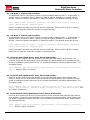
Absolute Encoder Wiring
RoboClaw is capable of reading absolute encoders that output an analog voltage. Like the Analog
input modes for controlling the motors, the absolute encoder voltage must be between 0v and
2v. If using standard potentiometers as absolute encoders the 5v from the RoboClaw can be
divided down to 2v at the potentiometer by adding a resistor from the 5v line on the RoboClaw
to the potentiometer. For a 5k pot R1 = 7.5k, for a 10k pot R1 = 15k and for a 20k pot R1 =
30k.
The diagram below shows the main battery as the only power source. Make sure the LB jumper
is set correctly. The 5VDC shown connected is only required if your MCU needs a power source.
This is the BEC feature of RoboClaw. If the MCU has its own power source do not the 5VDC.
UART TX
S1 Signal
UART RX
S2 Signal
M1A
5VDC
5VDC
Motor 1
GROUND
GROUND
M1B
Pot 1
A
GND
+2V
R1
Pot 2
A
GND
+2V
R1
EN1 A
GROUND
5VDC
Positive +
Negative
-
-
M2B
EN2 A
GROUND
5VDC
Motor 2
+
Battery
M2A
RoboClaw
Encoder/Motor Calibration for Velocity/Position Control
To control motors speed and/or position with encoders correctly the Roboclaw must have its
settings calibrated for the specific motors/encoders being used. The IonMotion software makes
calibrating manually easy and also offers an autotune function for both velocity and position
control modes.
Once the calibration settings for the specific mode you will be using(velocity, position or a
cascaded velocity/position control) are set and working correctly within the IonMotion software
the settings can be saved to the RoboClaw eeprom and will be loaded each time the unit powers
up.
RoboClaw Series User Manual
50
RoboClaw Series
Brushed DC Motor Controllers
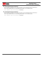
Velocity Manual Calibration Procedure
1. Determine the quadrature pulses per second(QPPS) value for your motor. The simplest
method to do this is to run the Motor at 100% duty using IonMotion and read back the speed
value from the encoder attached to the motor. If you are unable to run the motor like this due to
physical constraints you will need to estimate the maximum speed in encoder counts the motor
can produce.
2. Set the initial P,I and D values in the Velocity control window to 1,0 and 0. Try moving the
motor using the slider controls in IonMotion. If the motor does not move it may not be wired
correctly or the P value needs to be increased. If the motor immediately runs at max speed
when you change the slider position you probably have the motor or encoder wires reversed.
The motor is trying to go at the speed specified but the encoder reading is coming back in the
opposite direction so the motor increases power until it eventually hits 100% power. Reverse the
encoder or motor wires(not both) and test again.
3. Once the motor has some semblance of control you can set a moderate speed. Then start
increasing the P value until the speed reading is near the set value. If the motor feels like it is
vibrating at higher P values you should reduce the P value to about 2/3rds that value. Move on
to the I setting.
4. Start increasing the I setting. You will usually want to increase this value by .1 increments.
The I value helps the motor reach the exact speed specified. Too high an I value will also cause
the motor to feel rough/vibrate. This is because the motor will over shoot the set speed and then
the controller will reduce power to get the speed back down which will also under shoot and this
will continue oscillating back and forth form too fast to too slow, causing a vibration in the motor.
5. Once P and I are set reasonably well usually you will leave D = 0. D is only required if you are
unable to get reasonable speed control out of the motor using just P and I. D will help dampen
P and I over shoot allowing higher P and I values, but D also increases noise in the calculation
which can cause oscillations in the speed as well.
Position Manual Calibration Procedure
1. Position mode requires the Velocity mode QPPS value be set as described above. For simple
Position control you can set Velocity P, I and D all to 0.
2. Set the Position I and D settings to 0. Set the P setting to 2000 as a reasonable starting
point. To test the motor you must also set the Speed argument to some value. We recommend
setting it to the same value as the QPPS setting(eg maximum motor speed). Set the minimum
and maximum position values to safe numbers. If your motor has no dead stops this can be +-2
billion. If your motor has specific dead stops(like on a linear actuator) you will need to manually
move the motor to its dead stops to determine these numbers. Leave some margin infront of
each deadstop. Note that when using quadrature encoders you will need to home your motor on
every power up since the quadrature readings are all relative to the starting position unless you
set/reset the encoder values.
3. At this point the motor should move in the appropriate direction and stop, not necessarily
close to the set position when you move the slider. Increase the P setting until the position
is over shooting some each time you change the position slider. Now start increasing the D
setting(leave I at 0). Increasing D will add dampening to the movement when getting close
to the set position. This will help prevent the over shoot. D will usually be anywhere from 5 to
20 times larger than P but not always. Continue increasing P and D until the motor is working
reasonably well. Once it is you have tuned a simple PD system.
RoboClaw Series User Manual
51
RoboClaw Series
Brushed DC Motor Controllers
4. Once your position control is acting relatively smoothly and coming close to the set position
you can think about adjusting the I setting. Adding I will help reach the exact set point specified
but in most motor systems there is enough slop in the gears that instead you will end up causing
an oscillation around the specified position. This is called hunting. The I setting causes this when
there is any slop in the motor/encoder/gear train. You can compensate some for this by adding
deadzone. Deadzone is the area around the specified position the controller will consider to be
equal to the position specified.
5. One more setting must be adjusted in order to use the I setting. The Imax value sets the
maximum wind up allowed for the I setting calculation. Increasing Imax will allow I to affect a
larger amount of the movement of the motor but will also allow the system to oscillate if used
with a badly tuned I and/or set too high.
Auto tuning
IonMotion includes the option to autotune velocity and or position values. To use these options
you should first make sure your encoder and motor are running in the correct direction and
that basic PWM control of the motor works as expected. Then just click the autotune button for
the motor you want to tune. The autotune function will try to determine the best settings for
the motor. In the Velocity settings window it will autotune for velocity. In the Position Settings
window you have the option to tune a simple PD position controller, a PID position controller or
a cascaded Position/Velocity controller(PIV). The cascaded tune will determine both the velocity
and position values for the motor. Autotune functions usually return reasonable values but in
most cases you will still need to manually adjust them for optimum performance.
RoboClaw Series User Manual
52
RoboClaw Series
Brushed DC Motor Controllers
Encoder Commands
The following commands are used in dealing with the quadrature decoding counter registers. The
quadrature decoder is a simple counter that counts the incoming pulses, tracks the direction and
speed of each pulse. There are two registers one each for M1 and M2. (Note: A microcontroller
with a hardware UART is recommended for use with packet serial modes).
Command
Description
16
Read Encoder Register for M1.
17
Read Encoder Register for M2.
18
Read M1 Speed in Encoder Counts Per Second.
19
Read M2 Speed in Encoder Counts Per Second.
20
Resets Encoder Registers for M1 and M2(Quadrature only).
22
Set Encoder 1 Register(Quadrature only).
23
Set Encoder 2 Register(Quadrature only).
16 - Read Encoder Register M1
Read decoder M1 counter. Since CMD 16 is a read command it does not require a checksum.
However a checksum value will be returned from RoboClaw and can be used to validate the data.
Command syntax:
Send: [Address, CMD]
Receive: [Value1.Byte3, Value1.Byte2, Value1.Byte1, Value1.Byte0, Value2, Checksum]
The command will return 6 bytes. Byte 1,2,3 and 4 make up a long variable which is received
MSB first and represents the current count which can be any value from 0 - 4,294,967,295. With
quadrature encoders each pulse edge will increment or decrement the counter depending on the
direction of rotation. Absolute encoder values are converted from an analog voltage into a value
from 0 to 2047 for the full 2v range.
Byte 5 is the status byte for M1 decoder. It tracks counter underflow, direction, overflow and if
the encoder is operational. The byte value represents:
Bit0
Bit1
Bit2
Bit3
Bit4
Bit5
Bit6
Bit7
-
Counter Underflow (1= Underflow Occurred, Clear After Reading)
Direction (0 = Forward, 1 = Backwards)
Counter Overflow (1= Underflow Occurred, Clear After Reading)
Reserved
Reserved
Reserved
Reserved
Reserved
Byte 6 is the checksum. It is calculated the same way as sending a command, Sum all the
values sent and received except the checksum and mask the 8th bit.
RoboClaw Series User Manual
53
RoboClaw Series
Brushed DC Motor Controllers
17 - Read Quadrature Encoder Register M2
Read decoder M2 counter. Since CMD 16 is a read command it does not require a checksum.
However a checksum value will be returned from RoboClaw and can be used to validate the data.
Command syntax:
Send: [Address, CMD]
Receive: [Value1.Byte3, Value1.Byte2, Value1.Byte1, Value1.Byte0, Value2, Checksum]
The command will return 6 bytes. Byte 1,2,3 and 4 make up a long variable which is received
MSB first and represents the current count which can be any value from 0 - 4,294,967,295. With
quadrature encoders each pulse edge will increment or decrement the counter depending on the
direction of rotation. Absolute encoder values are converted from an analog voltage into a value
from 0 to 2047 for the full 2v range.
Byte 5 is the status byte for M1 decoder. It tracks counter underflow, direction, overflow and if
the encoder is operational. The byte value represents:
Bit0
Bit1
Bit2
Bit3
Bit4
Bit5
Bit6
Bit7
-
Counter Underflow (1= Underflow Occurred, Cleared After Reading)
Direction (0 = Forward, 1 = Backwards)
Counter Overflow (1= Underflow Occurred, Cleared After Reading)
Reserved
Reserved
Reserved
Reserved
Reserved
Byte 6 is the checksum.
18 - Read Speed M1
Read M1 counter speed. Returned value is in pulses per second. RoboClaw keeps track of how
many pulses received per second for both decoder channels. Since CMD 18 is a read command
it does not require a checksum to be sent. However a checksum value will be returned from
RoboClaw and can be used to validate the data. Command syntax:
Send: [Address, CMD]
Receive: [Value1.Byte3, Value1.Byte2, Value1.Byte1, Value1.Byte0, Value2, Checksum]
The command will return 6 bytes. Byte 1,2,3 and 4 make up a long variable which is received
MSB first and is the current count change per second which can be any value from 0 4,294,967,295. Byte 5 is the direction (0 – forward, 1 - backward). Byte 6 is the checksum.
RoboClaw Series User Manual
54
RoboClaw Series
Brushed DC Motor Controllers
19 - Read Speed M2
Read M2 counter speed. Returned value is in pulses per second. RoboClaw keeps track of how
many pulses received per second for both decoder channels. Since CMD 19 is a read command
it does not require a checksum to be sent. However a checksum value will be returned from
RoboClaw and can be used to validate the data. Command syntax:
Send: [Address, CMD]
Receive: [Value1.Byte3, Value1.Byte2, Value1.Byte1, Value1.Byte0, Value2, Checksum]
The command will return 6 bytes. Byte 1,2,3 and 4 make up a long variable which is received
MSB first and is the current count change per second which can be any value from 0 4,294,967,295. Byte 5 is the direction (0 – forward, 1 - backward). Byte 6 is the checksum.
20 - Reset Quadrature Encoder Counters
Will reset both quadrature decoder counters to zero. This command applies to quadrature
encoders only.
Send: [128, 20, ((128+20) & 0x7F)]
22 - Set Encoder 1 Register Value
Set the value of the Encoder 1 register. Useful when homing motor 1. This command applies to
quadrature encoders only.
Send: [Address, 22, Value(4 bytes), Checksum]
23 - Set Encoder 2 Register Value
Set the value of the Encoder 2 register. Useful when homing motor 2. This command applies to
quadrature encoders only.
Send: [Address, 23, Value(4 bytes), Checksum]
Advanced Motor Control
RoboClaw Series User Manual
55
RoboClaw Series
Brushed DC Motor Controllers
The following commands are used to control motor speeds, acceleration and distance using the
quadrature encoders. All speeds are given in quad pulses per second (QPPS) unless otherwise
stated. Quadrature encoders of different types and manufactures can be used. However many
have different resolutions and maximum speeds at which they operate. So each quadrature
encoder will produce a different range of pulses per second.
Command
Description
28
Set PID Constants for M1.
29
Set PID Constants for M2.
30
Read Current M1 Speed Resolution 125th of a Second.
31
Read Current M2 Speed Resolution 125th of a Second.
32
Drive M1 With Signed Duty Cycle. (Encoders not required)
33
Drive M2 With Signed Duty Cycle. (Encoders not required)
34
Mix Mode Drive M1 / M2 With Signed Duty Cycle. (Encoders not required)
35
Drive M1 With Signed Speed.
36
Drive M2 With Signed Speed.
37
Mix Mode Drive M1 / M2 With Signed Speed.
38
Drive M1 With Signed Speed And Acceleration.
39
Drive M2 With Signed Speed And Acceleration.
40
Mix Mode Drive M1 / M2 With Speed And Acceleration.
41
Drive M1 With Signed Speed And Distance. Buffered.
42
Drive M2 With Signed Speed And Distance. Buffered.
43
Mix Mode Drive M1 / M2 With Speed And Distance. Buffered.
44
Drive M1 With Signed Speed, Acceleration and Distance. Buffered.
45
Drive M2 With Signed Speed, Acceleration and Distance. Buffered.
46
Mix Mode Drive M1 / M2 With Speed, Acceleration And Distance. Buffered.
47
Read Buffer Length.
50
Mix Drive M1 / M2 With Individual Speed and Acceleration
51
Mix Drive M1 / M2 With Individual Speed, Accel and Distance
52
Drive M1 With Duty and Accel. (Encoders not required)
53
Drive M2 With Duty and Accel. (Encoders not required)
54
Mix Drive M1 / M2 With Duty and Accel. (Encoders not required)
61
Set Position PID Constants for M1.
62
Set Position PID Constants for M2
65
Drive M1 with signed Speed, Accel, Deccel and Position
66
Drive M2 with signed Speed, Accel, Deccel and Position
67
Drive M1 & M2 with signed Speed, Accel, Deccel and Position
68
Set default duty cycle acceleration for M1
69
Set default duty cycle acceleration for M2
RoboClaw Series User Manual
56
RoboClaw Series
Brushed DC Motor Controllers
28 - Set PID Constants M1
Several motor and quadrature combinations can be used with RoboClaw. In some cases the
default PID values will need to be tuned for the systems being driven. This gives greater
flexibility in what motor and encoder combinations can be used. The RoboClaw PID system
consist of four constants starting with QPPS, P = Proportional, I= Integral and D= Derivative.
The defaults values are:
QPPS = 44000
P = 0x00010000
I = 0x00008000
D = 0x00004000
QPPS is the speed of the encoder when the motor is at 100% power. P, I, D are the default
values used after a reset. Command syntax:
Send: [Address, 28, D(4 bytes), P(4 bytes), I(4 bytes), QPPS(4 byte), Checksum]
Each value is made up of 4 bytes for a long. To write the registers a checksum value is used.
This prevents an accidental write.
29 - Set PID Constants M2
Several motor and quadrature combinations can be used with RoboClaw. In some cases the
default PID values will need to be tuned for the systems being driven. This gives greater
flexibility in what motor and encoder combinations can be used. The RoboClaw PID system
consist of four constants starting with QPPS, P = Proportional, I= Integral and D= Derivative.
The defaults values are:
QPPS = 44000
P = 0x00010000
I = 0x00008000
D = 0x00004000
QPPS is the speed of the encoder when the motor is at 100% power. P, I, D are the default
values used after a reset. Command syntax:
Send: [Address, 29, D(4 bytes), P(4 bytes), I(4 bytes), QPPS(4 byte), Checksum]
Each value is made up of 4 bytes for a long. To write the registers a checksum value is used.
This prevents an accidental write.
RoboClaw Series User Manual
57
RoboClaw Series
Brushed DC Motor Controllers
30 - Read Current Speed M1
Read the current pulse per 125th of a second. This is a high resolution version of command
18 and 19. Command 30 can be used to make a independent PID routine. The resolution of
the command is required to create a PID routine using any microcontroller or PC used to drive
RoboClaw. The command syntax:
Send: [Address, CMD]
Receive: [Value1.Byte3, Value1.Byte2, Value1.Byte1, Value1.Byte0, Value2, Checksum]
The command will return 5 bytes, MSB sent first for a long. The first 4 bytes are a 32 byte value
(long) that repersent the speed. The 5th byte (Value2) is direction (0 – forward, 1 - backward).
is A checksum is returned in order to validate the data returned.
31 - Read Current Speed M2
Read the current pulse per 125th of a second. This is a high resolution version of command
18 and 19. Command 31 can be used to make a independent PID routine. The resolution of
the command is required to create a PID routine using any microcontroller or PC used to drive
RoboClaw. The command syntax:
Send: [Address, CMD]
Receive: [Value1.Byte3, Value1.Byte2, Value1.Byte1, Value1.Byte0, Value2, Checksum]
The command will return 5 bytes, MSB sent first for a long. The first 4 bytes are a 32 byte value
(long) that repersent the speed. The 5th byte (Value2) is direction (0 – forward, 1 - backward).
is A checksum is returned in order to validate the data returned.
32 - Drive M1 With Signed Duty Cycle
Drive M1 using a duty cycle value. The duty cycle is used to control the speed of the motor
without a quadrature encoder. The command syntax:
Send: [Address, CMD, Duty(2 Bytes), Checksum]
The duty value is signed and the range is -32768 to +32767.
33 - Drive M2 With Signed Duty Cycle
Drive M2 using a duty cycle value. The duty cycle is used to control the speed of the motor
without a quadrature encoder. The command syntax:
Send: [Address, CMD, Duty(2 Bytes), Checksum]
The duty value is signed and the range is -32768 to +32767.
RoboClaw Series User Manual
58
RoboClaw Series
Brushed DC Motor Controllers
34 - Drive M1 / M2 With Signed Duty Cycle
Drive both M1 and M2 using a duty cycle value. The duty cycle is used to control the speed of
the motor without a quadrature encoder. The command syntax:
Send: [Address, CMD, DutyM1(2 Bytes), DutyM2(2 Bytes), Checksum]
The duty value is signed and the range is -32768 to +32767.
35 - Drive M1 With Signed Speed
Drive M1 using a speed value. The sign indicates which direction the motor will turn. This
command is used to drive the motor by quad pulses per second. Different quadrature encoders
will have different rates at which they generate the incoming pulses. The values used will differ
from one encoder to another. Once a value is sent the motor will begin to accelerate as fast as
possible until the defined rate is reached. The command syntax:
Send: [Address, CMD, Qspeed(4 Bytes), Checksum]
4 Bytes (long) are used to express the pulses per second. Quadrature encoders send 4 pulses
per tick. So 1000 ticks would be counted as 4000 pulses.
36 - Drive M2 With Signed Speed
Drive M2 with a speed value. The sign indicates which direction the motor will turn. This
command is used to drive the motor by quad pulses per second. Different quadrature encoders
will have different rates at which they generate the incoming pulses. The values used will differ
from one encoder to another. Once a value is sent, the motor will begin to accelerate as fast as
possible until the rate defined is reached. The command syntax:
Send: [Address, CMD, Qspeed(4 Bytes), Checksum]
4 Bytes (long) are used to expressed the pulses per second. Quadrature encoders send 4 pulses
per tick. So 1000 ticks would be counted as 4000 pulses.
RoboClaw Series User Manual
59
RoboClaw Series
Brushed DC Motor Controllers
37 - Drive M1 / M2 With Signed Speed
Drive M1 and M2 in the same command using a signed speed value. The sign indicates which
direction the motor will turn. This command is used to drive both motors by quad pulses per
second. Different quadrature encoders will have different rates at which they generate the
incoming pulses. The values used will differ from one encoder to another. Once a value is sent
the motor will begin to accelerate as fast as possible until the rate defined is reached. The
command syntax:
Send: [Address, CMD, QspeedM1(4 Bytes), QspeedM2(4 Bytes), Checksum]
4 Bytes (long) are used to express the pulses per second. Quadrature encoders send 4 pulses
per tick. So 1000 ticks would be counted as 4000 pulses.
38 - Drive M1 With Signed Speed And Acceleration
Drive M1 with a signed speed and acceleration value. The sign indicates which direction the
motor will run. The acceleration values are not signed. This command is used to drive the motor
by quad pulses per second and using an acceleration value for ramping. Different quadrature
encoders will have different rates at which they generate the incoming pulses. The values used
will differ from one encoder to another. Once a value is sent the motor will begin to accelerate
incrementally until the rate defined is reached. The command syntax:
Send: [Address, CMD, Accel(4 Bytes), Qspeed(4 Bytes), Checksum]
4 Bytes (long) are used to express the pulses per second. Quadrature encoders send 4 pulses
per tick. So 1000 ticks would be counted as 4000 pulses. The acceleration is measured
in speed per second. An acceleration value of 12,000 QPPS with a speed of 12,000 QPPS
would accelerate a motor from 0 to 12,000 QPPS in 1 second. Another example would be an
acceleration value of 24,000 QPPS and a speed value of 12,000 QPPS would accelerate the motor
to 12,000 QPPS in 0.5 seconds.
39 - Drive M2 With Signed Speed And Acceleration
Drive M2 with a signed speed and acceleration value. The sign indicates which direction the
motor will run. The acceleration value is not signed. This command is used to drive the motor
by quad pulses per second and using an acceleration value for ramping. Different quadrature
encoders will have different rates at which they generate the incoming pulses. The values used
will differ from one encoder to another. Once a value is sent the motor will begin to accelerate
incrementally until the rate defined is reached. The command syntax:
Send: [Address, CMD, Accel(4 Bytes), Qspeed(4 Bytes), Checksum]
4 Bytes (long) are used to express the pulses per second. Quadrature encoders send 4 pulses
per tick. So 1000 ticks would be counted as 4000 pulses. The acceleration is measured
in speed per second. An acceleration value of 12,000 QPPS with a speed of 12,000 QPPS
would accelerate a motor from 0 to 12,000 QPPS in 1 second. Another example would be an
acceleration value of 24,000 QPPS and a speed value of 12,000 QPPS would accelerate the motor
to 12,000 QPPS in 0.5 seconds.
RoboClaw Series User Manual
60
RoboClaw Series
Brushed DC Motor Controllers
40 - Drive M1 / M2 With Signed Speed And Acceleration
Drive M1 and M2 in the same command using one value for acceleration and two signed speed
values for each motor. The sign indicates which direction the motor will run. The acceleration
value is not signed. The motors are sync during acceleration. This command is used to drive
the motor by quad pulses per second and using an acceleration value for ramping. Different
quadrature encoders will have different rates at which they generate the incoming pulses. The
values used will differ from one encoder to another. Once a value is sent the motor will begin to
accelerate incrementally until the rate defined is reached. The command syntax:
Send: [Address, CMD, Accel(4 Bytes), QspeedM1(4 Bytes), QspeedM2(4 Bytes), Checksum]
4 Bytes (long) are used to express the pulses per second. Quadrature encoders send 4 pulses
per tick. So 1000 ticks would be counted as 4000 pulses. The acceleration is measured
in speed per second. An acceleration value of 12,000 QPPS with a speed of 12,000 QPPS
would accelerate a motor from 0 to 12,000 QPPS in 1 second. Another example would be an
acceleration value of 24,000 QPPS and a speed value of 12,000 QPPS would accelerate the motor
to 12,000 QPPS in 0.5 seconds.
41 - Buffered M1 Drive With Signed Speed And Distance
Drive M1 with a signed speed and distance value. The sign indicates which direction the motor
will run. The distance value is not signed. This command is buffered. This command is used to
control the top speed and total distance traveled by the motor. Each motor channel M1 and M2
have separate buffers. This command will execute immediately if no other command for that
channel is executing, otherwise the command will be buffered in the order it was sent. Any
buffered or executing command can be stopped when a new command is issued by setting the
Buffer argument. All values used are in quad pulses per second. The command syntax:
Send: [Address, CMD, QSpeed(4 Bytes), Distance(4 Bytes), Buffer(1 Byte), Checksum]
4 Bytes(long) are used to express the pulses per second. The Buffer argument can be set to a
1 or 0. If a value of 0 is used the command will be buffered and executed in the order sent. If
a value of 1 is used the current running command is stopped, any other commands in the buffer
are deleted and the new command is executed.
42 - Buffered M2 Drive With Signed Speed And Distance
Drive M2 with a speed and distance value. The sign indicates which direction the motor will run.
The distance value is not signed. This command is buffered. Each motor channel M1 and M2
have separate buffers. This command will execute immediately if no other command for that
channel is executing, otherwise the command will be buffered in the order it was sent. Any
buffered or executing command can be stopped when a new command is issued by setting the
Buffer argument. All values used are in quad pulses per second. The command syntax:
Send: [Address, CMD, QSpeed(4 Bytes), Distance(4 Bytes), Buffer(1 Byte), Checksum]
4 Bytes(long) are used to express the pulses per second. The Buffer argument can be set to a
1 or 0. If a value of 0 is used the command will be buffered and executed in the order sent. If
a value of 1 is used the current running command is stopped, any other commands in the buffer
are deleted and the new command is executed.
RoboClaw Series User Manual
61
RoboClaw Series
Brushed DC Motor Controllers
43 - Buffered Drive M1 / M2 With Signed Speed And Distance
Drive M1 and M2 with a speed and distance value. The sign indicates which direction the motor
will run. The distance value is not signed. This command is buffered. Each motor channel M1
and M2 have separate buffers. This command will execute immediately if no other command for
that channel is executing, otherwise the command will be buffered in the order it was sent. Any
buffered or executing command can be stopped when a new command is issued by setting the
Buffer argument. All values used are in quad pulses per second. The command syntax:
Send: [Address, CMD, QSpeedM1(4 Bytes), DistanceM1(4 Bytes),
QSpeedM2(4 Bytes), DistanceM2(4 Bytes), Buffer(1 Byte), Checksum]
4 Bytes(long) are used to express the pulses per second. The Buffer argument can be set to a
1 or 0. If a value of 0 is used the command will be buffered and executed in the order sent. If
a value of 1 is used the current running command is stopped, any other commands in the buffer
are deleted and the new command is executed.
44 - Buffered M1 Drive With Signed Speed, Accel And Distance
Drive M1 with a speed, acceleration and distance value. The sign indicates which direction the
motor will run. The acceleration and distance values are not signed. This command is used to
control the motors top speed, total distanced traveled and at what incremental acceleration
value to use until the top speed is reached. Each motor channel M1 and M2 have separate
buffers. This command will execute immediately if no other command for that channel is
executing, otherwise the command will be buffered in the order it was sent. Any buffered
or executing command can be stopped when a new command is issued by setting the Buffer
argument. All values used are in quad pulses per second. The command syntax:
Send: [Address, CMD, Accel(4 bytes), QSpeed(4 Bytes), Distance(4 Bytes),
Buffer(1 Byte), Checksum]
4 Bytes(long) are used to express the pulses per second. The Buffer argument can be set to a
1 or 0. If a value of 0 is used the command will be buffered and executed in the order sent. If
a value of 1 is used the current running command is stopped, any other commands in the buffer
are deleted and the new command is executed.
45 - Buffered M2 Drive With Signed Speed, Accel And Distance
Drive M2 with a speed, acceleration and distance value. The sign indicates which direction the
motor will run. The acceleration and distance values are not signed. This command is used to
control the motors top speed, total distanced traveled and at what incremental acceleration
value to use until the top speed is reached. Each motor channel M1 and M2 have separate
buffers. This command will execute immediately if no other command for that channel is
executing, otherwise the command will be buffered in the order it was sent. Any buffered
or executing command can be stopped when a new command is issued by setting the Buffer
argument. All values used are in quad pulses per second. The command syntax:
Send: [Address, CMD, Accel(4 bytes), QSpeed(4 Bytes), Distance(4 Bytes),
Buffer(1 Byte), Checksum]
4 Bytes(long) are used to express the pulses per second. The Buffer argument can be set to a
1 or 0. If a value of 0 is used the command will be buffered and executed in the order sent. If
a value of 1 is used the current running command is stopped, any other commands in the buffer
are deleted and the new command is executed.
RoboClaw Series User Manual
62
RoboClaw Series
Brushed DC Motor Controllers
46 - Drive M1 / M2 With Signed Speed, Accel And Distance
Drive M1 and M2 with a speed, acceleration and distance value. The sign indicates which
direction the motor will run. The acceleration and distance values are not signed. This command
is used to control both motors top speed, total distanced traveled and at what incremental
acceleration value to use until the top speed is reached. Each motor channel M1 and M2 have
separate buffers. This command will execute immediately if no other command for that channel
is executing, otherwise the command will be buffered in the order it was sent. Any buffered
or executing command can be stopped when a new command is issued by setting the Buffer
argument. All values used are in quad pulses per second. The command syntax:
Send: [Address, CMD, Accel(4 Bytes), QSpeedM1(4 Bytes), DistanceM1(4 Bytes),
QSpeedM2(4 bytes), DistanceM2(4 Bytes), Buffer(1 Byte), Checksum]
4 Bytes(long) are used to express the pulses per second. The Buffer argument can be set to a
1 or 0. If a value of 0 is used the command will be buffered and executed in the order sent. If
a value of 1 is used the current running command is stopped, any other commands in the buffer
are deleted and the new command is executed.
47 - Read Buffer Length
Read both motor M1 and M2 buffer lengths. This command can be used to determine how many
commands are waiting to execute.
Send: [Address, CMD]
Receive: [BufferM1(1 Bytes), BufferM2(1 Bytes), Checksum]
The return values represent how many commands per buffer are waiting to be executed. The
maximum buffer size per motor is 31 commands. A return value of 0x80(128) indicates the
buffer is empty. A return value of 0 indiciates the last command sent is executing. A value of
0x80 indicates the last command buffered has finished.
50 - Drive M1 / M2 With Speed And Individual Acceleration
Drive M1 and M2 in the same command using one value for acceleration and two signed speed
values for each motor. The sign indicates which direction the motor will run. The acceleration
value is not signed. The motors are sync during acceleration. This command is used to drive
the motor by quad pulses per second and using an acceleration value for ramping. Different
quadrature encoders will have different rates at which they generate the incoming pulses. The
values used will differ from one encoder to another. Once a value is sent the motor will begin to
accelerate incrementally until the rate defined is reached. The command syntax:
Send: [Address, CMD, AccelM1(4 Bytes), QspeedM1(4 Bytes), AccelM2(4 Bytes), QspeedM2(4
Bytes), Checksum]
4 Bytes (long) are used to express the pulses per second. Quadrature encoders send 4 pulses
per tick. So 1000 ticks would be counted as 4000 pulses. The acceleration is measured
in speed per second. An acceleration value of 12,000 QPPS with a speed of 12,000 QPPS
would accelerate a motor from 0 to 12,000 QPPS in 1 second. Another example would be an
acceleration value of 24,000 QPPS and a speed value of 12,000 QPPS would accelerate the motor
to 12,000 QPPS in 0.5 seconds.
RoboClaw Series User Manual
63
RoboClaw Series
Brushed DC Motor Controllers
51 - Drive M1 / M2 Speed, Individual Accel And Distance
Drive M1 and M2 with a speed, acceleration and distance value. The sign indicates which
direction the motor will run. The acceleration and distance values are not signed. This command
is used to control both motors top speed, total distanced traveled and at what incremental
acceleration value to use until the top speed is reached. Each motor channel M1 and M2 have
separate buffers. This command will execute immediately if no other command for that channel
is executing, otherwise the command will be buffered in the order it was sent. Any buffered
or executing command can be stopped when a new command is issued by setting the Buffer
argument. All values used are in quad pulses per second. The command syntax:
Send: [Address, CMD, AccelM1(4 Bytes), QSpeedM1(4 Bytes), DistanceM1(4 Bytes), AccelM2(4 Bytes), QSpeedM2(4 bytes), DistanceM2(4 Bytes), Buffer(1 Byte), Checksum]
4 Bytes(long) are used to express the pulses per second. The Buffer argument can be set to a
1 or 0. If a value of 0 is used the command will be buffered and executed in the order sent. If
a value of 1 is used the current running command is stopped, any other commands in the buffer
are deleted and the new command is executed.
52 - Drive M1 With Signed Duty And Acceleration
Drive M1 with a signed duty and acceleration value. The sign indicates which direction the motor
will run. The acceleration values are not signed. This command is used to drive the motor by
PWM and using an acceleration value for ramping. Accel is the rate per second at which the duty
changes from the current duty to the specified duty. The command syntax:
Send: [Address, CMD, Duty(2 bytes), Accel(2 Bytes), Checksum]
The duty value is signed and the range is -32768 to +32767. The accel value range is 0 to
655359.
53 - Drive M2 With Signed Duty And Acceleration
Drive M1 with a signed duty and acceleration value. The sign indicates which direction the motor
will run. The acceleration values are not signed. This command is used to drive the motor by
PWM and using an acceleration value for ramping. Accel is the rate at which the duty changes
from the current duty to the specified dury. The command syntax:
Send: [Address, CMD, Duty(2 bytes), Accel(2 Bytes), Checksum]
The duty value is signed and the range is -32768 to +32767. The accel value range is 0 to
655359.
54 - Drive M1 / M2 With Signed Duty And Acceleration
Drive M1 and M2 in the same command using acceleration and duty values for each motor.
The sign indicates which direction the motor will run. The acceleration value is not signed. This
command is used to drive the motor by PWM using an acceleration value for ramping. The
command syntax:
Send: [Address, CMD, DutyM1(2 bytes), Accelm1(4 Bytes), DutyM2(2 bytes), AccelM1(4
bytes), Checksum]
The duty value is signed and the range is -32768 to +32767. The accel value range is 0 to
655359.
RoboClaw Series User Manual
64
RoboClaw Series
Brushed DC Motor Controllers
61 - Set Motor 1 Position PID Constants
The RoboClaw Position PID system consist of seven constants starting with P = Proportional, I=
Integral and D= Derivative, MaxI = Maximum Integral windup, Deadzone in encoder counts,
MinPos = Minimum Position and MaxPos = Maximum Position. The defaults values are all zero.
Send: [Address, CMD, P(4 bytes), I(4 bytes), D(4 bytes), MaxI(4 bytes), Deadzone(4
bytes), MinPos(4 bytes), MaxPos(4 bytes)
Position constants are used only with the Position commands, 65,66 and 67 and RC or Analog
mode when in absolute mode with encoders or potentiometers.
62 - Set Motor 2 Position PID Constants
The RoboClaw Position PID system consist of seven constants starting with P = Proportional, I=
Integral and D= Derivative, MaxI = Maximum Integral windup, Deadzone in encoder counts,
MinPos = Minimum Position and MaxPos = Maximum Position. The defaults values are all zero.
Send: [Address, CMD, P(4 bytes), I(4 bytes), D(4 bytes), MaxI(4 bytes), Deadzone(4
bytes), MinPos(4 bytes), MaxPos(4 bytes)
Position constants are used only with the Position commands, 65,66 and 67 and RC or Analog
mode when in absolute mode with encoders or potentiometers.
65 - Drive M1 with signed Speed, Accel, Deccel and Position
Move M1 position from the current position to the specified new position and hold the new
position. Accel sets the acceleration value and deccel the decceleration value. QSpeed sets the
speed in quadrature pulses the motor will run at after acceleration and before decceleration. The
command syntax:
Send: [Address, CMD, Accel(4 bytes), QSpeed(4 Bytes), Deccel(4 bytes), Position(4
Bytes), Buffer(1 Byte), Checksum]
66 - Drive M2 with signed Speed, Accel, Deccel and Position
Move M2 position from the current position to the specified new position and hold the new
position. Accel sets the acceleration value and deccel the decceleration value. QSpeed sets the
speed in quadrature pulses the motor will run at after acceleration and before decceleration. The
command syntax:
Send: [Address, CMD, Accel1(4 bytes), QSpeed1(4 Bytes), Deccel1(4 bytes), Position1(4
Bytes), Accel2(4 bytes), QSpeed2(4 Bytes), Deccel2(4 bytes), Position2(4 Bytes), Buffer(1 Byte), Checksum]
67 - Drive M1 & M2 with signed Speed, Accel, Deccel and Position
Move M1 & M2 positions from their current positions to the specified new positions and hold the
new positions. Accel sets the acceleration value and deccel the decceleration value. QSpeed sets
the speed in quadrature pulses the motor will run at after acceleration and before decceleration.
The command syntax:
Send: [Address, CMD, Accel(4 bytes), QSpeed(4 Bytes), Deccel(4 bytes), Position(4
Bytes),Buffer(1 Byte), Checksum]
RoboClaw Series User Manual
65
RoboClaw Series
Brushed DC Motor Controllers
68 - Set M1 Default Duty Acceleration
Set the default acceleration for M1 when using duty cycle commands(Cmds 32,33 and 34) or
when using Standard Serial, RC and Analog PWM modes. The command syntax:
Send: [Address, CMD, Accel(4 bytes), Checksum]
69 - Set M2 Default Duty Acceleration
Set the default acceleration for M2 when using duty cycle commands(Cmds 32,33 and 34) or
when using Standard Serial, RC and Analog PWM modes. The command syntax:
Send: [Address, CMD, Accel(4 bytes), Checksum]
RoboClaw Series User Manual
66
RoboClaw Series
Brushed DC Motor Controllers
Reading Quadrature Encoder - Arduino Example
The example was tested with an Arduino Uno using packet serial wiring and quadrature encoder
wiring diagrams. The example will read the speed, total ticks and direction of each encoder.
Connect to the program using a terminal window set to 38400 baud. The program will display
the values of each encoders current count along with each encoder status bit in binary and the
direction bit. As the encoder is turned it will update the screen.
//RoboClaw Packet Serial Mode.
//Switch settings: SW3=ON, SW4=ON, SW5=ON
#include “BMSerial.h”
#include “RoboClaw.h”
#define address 0x80
#define
#define
#define
#define
Kp 0x00010000
Ki 0x00008000
Kd 0x00004000
qpps 44000
BMSerial terminal(0,1);
RoboClaw roboclaw(5,6,10000);
void setup() {
terminal.begin(38400);
roboclaw.begin(38400);
}
roboclaw.SetM1Constants(address,Kd,Kp,Ki,qpps);
roboclaw.SetM2Constants(address,Kd,Kp,Ki,qpps);
void loop() {
uint8_t status;
bool valid;
uint32_t enc1= roboclaw.ReadEncM1(address, &status, &valid);
if(valid){
terminal.print(“Encoder1:”);
terminal.print(enc1,HEX);
terminal.print(“ “);
terminal.print(status,HEX);
terminal.print(“ “);
}
uint32_t enc2 = roboclaw.ReadEncM2(address, &status, &valid);
if(valid){
terminal.print(“Encoder2:”);
terminal.print(enc2,HEX);
terminal.print(“ “);
terminal.print(status,HEX);
terminal.print(“ “);
}
uint32_t speed1 = roboclaw.ReadSpeedM1(address, &status, &valid);
if(valid){
terminal.print(“Speed1:”);
terminal.print(speed1,HEX);
terminal.print(“ “);
}
uint32_t speed2 = roboclaw.ReadSpeedM2(address, &status, &valid);
if(valid){
terminal.print(“Speed2:”);
terminal.print(speed2,HEX);
terminal.print(“ “);
}
terminal.println();
}
delay(100);
RoboClaw Series User Manual
67
RoboClaw Series
Brushed DC Motor Controllers
Speed Controlled by Quadrature Encoders - Arduino Example
The following example was written using an Arduino UNO using packet serial wiring and
quadrature encoder wiring diagrams. The example will command a 4wheel robot to move
forward, backward, right turn and left turn slowly. You can change the speed by adjusting the
value of Speed and Speed2 variables.
//RoboClaw Packet Serial Mode.
//Switch settings: SW3=ON, SW4=ON, SW5=ON
#include “BMSerial.h”
#include “RoboClaw.h”
#define address 0x80
#define
#define
#define
#define
Kp 0x00010000
Ki 0x00008000
Kd 0x00004000
qpps 44000
BMSerial terminal(0,1);
RoboClaw roboclaw(5,6,10000);
void setup() {
terminal.begin(38400);
roboclaw.begin(38400);
}
roboclaw.SetM1Constants(address,Kd,Kp,Ki,qpps);
roboclaw.SetM2Constants(address,Kd,Kp,Ki,qpps);
void displayspeed(void)
{
uint8_t status;
bool valid;
uint32_t enc1= roboclaw.ReadEncM1(address, &status, &valid);
if(valid){
terminal.print(“Encoder1:”);
terminal.print(enc1,DEC);
terminal.print(“ “);
terminal.print(status,HEX);
terminal.print(“ “);
}
uint32_t enc2 = roboclaw.ReadEncM2(address, &status, &valid);
if(valid){
terminal.print(“Encoder2:”);
terminal.print(enc2,DEC);
terminal.print(“ “);
terminal.print(status,HEX);
terminal.print(“ “);
}
RoboClaw Series User Manual
68
RoboClaw Series
Brushed DC Motor Controllers
uint32_t speed1 = roboclaw.ReadSpeedM1(address, &status, &valid);
if(valid){
terminal.print(“Speed1:”);
terminal.print(speed1,DEC);
terminal.print(“ “);
}
uint32_t speed2 = roboclaw.ReadSpeedM2(address, &status, &valid);
if(valid){
terminal.print(“Speed2:”);
terminal.print(speed2,DEC);
terminal.print(“ “);
}
terminal.println();
}
void loop() {
roboclaw.SpeedAccelDistanceM1(address,12000,12000,48000);
uint8_t depth1,depth2;
do{
displayspeed();
roboclaw.ReadBuffers(address,depth1,depth2);
}while(depth1);
roboclaw.SpeedAccelDistanceM1(address,12000,-12000,48000);
do{
displayspeed();
roboclaw.ReadBuffers(address,depth1,depth2);
}while(depth1);
}
RoboClaw Series User Manual
69
RoboClaw Series
Brushed DC Motor Controllers
RoboClaw Electrical Specifications
Characteristic
Model
Rating
Min
Pulse Per Second
All
PPS
0
Logic Battery
All
VDC
6
Main Battery
2x5A
VDC
6
34
2x15A
VDC
6
34
2x30A
VDC
6
34
2x60A
VDC
6
34
2x60A HV
VDC
10.5
60
2x5A
mA
200
2x15A
A
3
2x30A
A
3
2x60A
A
3
2x60A HV
mA
External Current Draw (BEC)
Motor Current Per Channel
Typ
Max
8,000,000
12
34
200
2
101
2x15A
152
301
2x30A
302
601
2x60A
602
1201
2x60A HV
602
1201
2x5A
A
5
Logic Circuit
All
mA
30
I/O Input
All
VDC
0
5
I/O Output
All
VDC
0
3.3
Analog Voltage Range
All
VDC
0
2
Tempature Range
All
C
-40
40
+100
Note 1: Maximum current is automatically reduced to the rated current limit within 2.5 seconds
Note 2: Current is limited by maximum temperature. Starting at 85c, the current limit is reduced on a
slope with a maximum temperature of 100c, which will reduce the current to 0 amps.
RoboClaw Series User Manual
70
RoboClaw Series
Brushed DC Motor Controllers
Warranty
IonMC warranties its products against defects in material and workmanship for a period of
90 days. If a defect is discovered, IonMC will, at our discretion, repair, replace, or refund the
purchase price of the product in question. Contact us at [email protected]. No returns will be
accepted without the proper authorization.
Copyrights and Trademarks
Copyright© 2014 by IonMC, Inc. All rights reserved. RoboClaw and USB RoboClaw are registered
trademarks of IonMC, Inc. Other trademarks mentioned are registered trademarks of their
respective holders.
Disclaimer
IonMC cannot be held responsible for any incidental, or consequential damages resulting from
use of products manufactured or sold by IonMC or its distributors. No products from IonMC
should be used in any medical devices and/or medical situations. No product should be used in a
life support situation.
Contacts
Email: [email protected]
Tech support: [email protected]
Web: http://www.ionmc.com
Discussion List
A web based discussion board is maintained at http://forums.ionmc.com.
Technical Support
Technical support is made available by sending an email to [email protected]. All email will be
answered within 48 hours.
RoboClaw Series User Manual
71