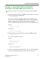
1
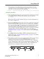
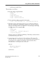
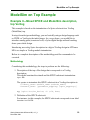
Getting Started with ADVance MS Software Version 1.5_1 Release 2001.3 Copyright Mentor Graphics Corporation 2001. All rights reserved. This document contains information that is proprietary to Mentor Graphics Corporation. The original recipient of this document may duplicate this document in whole or in part for internal business purposes only, provided that this entire notice appears in all copies. In duplicating any part of this document, the recipient agrees to make every reasonable effort to prevent the unauthorized use and distribution of the proprietary information. End-User License Agreement Trademark Information This document is for information and instruction purposes. Mentor Graphics reserves the right to make changes in specifications and other information contained in this publication without prior notice, and the reader should, in all cases, consult Mentor Graphics to determine whether any changes have been made. The terms and conditions governing the sale and licensing of Mentor Graphics products are set forth in written agreements between Mentor Graphics and its customers. No representation or other affirmation of fact contained in this publication shall be deemed to be a warranty or give rise to any liability of Mentor Graphics whatsoever. MENTOR GRAPHICS MAKES NO WARRANTY OF ANY KIND WITH REGARD TO THIS MATERIAL INCLUDING, BUT NOT LIMITED TO, THE IMPLIED WARRANTIES OR MERCHANTABILITY AND FITNESS FOR A PARTICULAR PURPOSE. MENTOR GRAPHICS SHALL NOT BE LIABLE FOR ANY INCIDENTAL, INDIRECT, SPECIAL, OR CONSEQUENTIAL DAMAGES WHATSOEVER (INCLUDING BUT NOT LIMITED TO LOST PROFITS) ARISING OUT OF OR RELATED TO THIS PUBLICATION OR THE INFORMATION CONTAINED IN IT, EVEN IF MENTOR GRAPHICS CORPORATION HAS BEEN ADVISED OF THE POSSIBILITY OF SUCH DAMAGES. RESTRICTED RIGHTS LEGEND 03/97 U.S. Government Restricted Rights. The SOFTWARE and documentation have been developed entirely at private expense and are commercial computer software provided with restricted rights. Use, duplication or disclosure by the U.S. Government or a U.S. Government subcontractor is subject to the restrictions set forth in the license agreement provided with the software pursuant to DFARS 227.72023(a) or as set forth in subparagraph (c)(1) and (2) of the Commercial Computer Software - Restricted Rights clause at FAR 52.227-19, as applicable. Contractor/manufacturer is: Mentor Graphics Corporation 8005 S.W. Boeckman Road, Wilsonville, Oregon 97070-7777. This is an unpublished work of Mentor Graphics Corporation. Getting Started with ADVance MS Introduction The purpose of this chapter is to help you install and become familiar with ADVance MS, so you can start experimenting with VHDL-AMS. Towards the end of the chapter there are guidelines on using both ADVance MS and ModelSim together. Installing ADVance MS You must install the Cygnus GNUPro Tool Kit, the product software, and your license before you can begin to use ADVance MS. Installing the Cygnus GNUPro tool kit You will need the Cygnus June 2000 Release CD, Mentor Part number 206710. Follow the instructions in the CD booklet to mount the CD and then use the information in the README file at the root to complete the installation. You are making a “non-Falcon” installation, therefore you need to follow instructions 1 to 7, followed by the instructions under “Non-Falcon based Installation” which begin approximately halfway through the README file. Installing ADVance MS and ModelSim software You will need the ADVance MS CD. Follow the instructions in the CD booklet to mount the disk and start the installation program. Select the appropriate architecture (for example, Sun OS 5.6) and install “ALL” software. Select the “platform independent” item and install the “documentation.” Getting Started with ADVance MS, v1.5_1 December 2001 3 Running your first VHDL-AMS design Please note that the installation of ModelSim is embedded within ADVance MS. This is transparent to the user. Note Section 5 of the Installation Guide (supplied both as a PostScript file at the root of the CD, and as a PDF file) describes how to use the licensing system supplied with ADVance MS. The installation procedure provides the option of performing a basic installation of the licensing system. The installation procedure will optionally modify a user’s .cshrc or .profile file to add initialization items for ADVance MS. After installation is complete, run a “systest” by typing the following command: /bin/sh $anacad/adms/$admsver/examples/test.adms This will run a test to verify that the software has been installed correctly. Running your first VHDL-AMS design on ADVance MS User initialization sets the environment variable anacad to point to the root of the ADVance MS installation and sources the $anacad/com/init_anacad file. In addition, be sure to have access to the Cygnus gcc executables with your path environment variable. Using ADVance MS The first two examples in this chapter contain Pure VHDL-AMS and Mixed VHDL-AMS—Spice descriptions. This follows the ADC12 design, which is provided as an example with the product. • Copy the sample model directory to your default directory: $ cp $anacad/adms/$admsver/examples/adc12/* . 4 Getting Started with ADVance MS, v1.5_1 December 2001 Using ADVance MS When you look at the description, you will see that the files listed below contain the following design units: • adc12-ms.vhd (pure digital description) o entity multi_clock o architecture multi_clock(modelsim) o entity dlatch o architecture dlatch(modelsim) o entity sar o architecture sar(modelsim). • adc12-adms.vhd (contains mixed descriptions) o architecture adc12(structural) o architecture test(adc12test). • adc12-all-adms.vhd (contains digital, analog, and mixed descriptions) o architecture multi_clock(adms) o architecture dlatch(adms) o architecture sar(adms) o entity dac o architecture dac(behavioral) o entity comp o architecture comp(behavioral) o entity dtoa Getting Started with ADVance MS, v1.5_1 December 2001 5 Using ADVance MS o architecture dtoa(behavioral) o entity d2a o architecture d2a(structural) o entity adc12. Example 1—Pure VHDL-AMS description • Before you can compile your design, you must create a library to store the compilation results. Use “valib” on page 8-16 to create a new library. Create the working library in your current default directory from the Unix command line: $ valib ADC12 • You will receive progress messages as the various steps in creating the library are executed. The result will be a directory ADC12 in your default directory. If you get messages indicating that valib “can’t find” various items, it is probably because you have not run the ADVance MS set up script. In subsequent sessions you will need to execute the following command to restore the working library definition: $ vasetlib ADC12 Refer to “Using Design Libraries” on page 3-1, for additional information on working with libraries. • Compile the model from the Unix command line: $ vacom adc12-ms.vhd $ vacom adc12-all-adms.vhd $ vacom adc12-adms.vhd The ADVance MS compiler compiles one or more VHDL-AMS design units with a single invocation of “vacom” on page 8-2. The design units are compiled in the order that they appear on the command line. For ADVance MS, the order of compilation is important—you must compile any entities or configurations before an architecture that references them. 6 Getting Started with ADVance MS, v1.5_1 December 2001 Using ADVance MS You can choose to use either batch or interactive simulation. Use the command below for a batch simulation, using Xelga to view the results (.dou and .cou files) at the end of the simulation: $ vasim -c -cmd adc12test.cmd TEST ADC12TEST -do adc12test.do Interactive simulation • After compiling the design units, you can proceed to simulate your designs with vasim, the MGC ADVance MS simulator. Start the simulator: $ vasim Refer to the ADVance MS Command Reference for more information on the “vasim” on page 8-26. • Bring the Load Design window to the front. Select architecture design unit ADC12TEST under TEST, select the adc12test.cmd file in the “command file” frame and click Load. The appropriate text command will be echoed to the main window (on the upper left of the screen) and you will see a series of progress messages ending with Load done. In general, each menu command will be echoed to the main window in text form. Refer to “Simulation startup” on page 9-53 for further details on the Load Design window. • In the Main window select View Þ All. Six additional windows will appear. Refer to the “ADVance MS Main window” on page 9-7 for further details on the Main window. • The model is a twelve bit, successive approximation A/D converter. Select instance u1:adc12(structural) in the Structure window to see the components. In data-flow order they are: one-bit DAC (dac), comparator (comp), D-latch (dlatch), and successive approximation register (sar). The output of sar is fed back to the input of the dac. The sar and dlatch are clocked by non-overlapping clocks generated by multi_clock. q Tvout dac outcomp_d comp datab dlatch sar eoc Tvbg Tvin Getting Started with ADVance MS, v1.5_1 December 2001 clk2 comset clk1 7 Using ADVance MS Refer to the Structure window for further details. • In the Nets window, hold down the control key and select the following nets: clk1, clk2, comset, eoc, q, tvin, and tvout. (Note this can be executed only if you previously selected 'u1' instance in the Structure window as in the step above.) clk1 is the sar clock, clk2 is the dlatch clock, comset is the sar enable line, eoc is the sar conversion complete output signal, q is the digital output, tvin is the analog input and tvout is the DAC output that feeds the comparator. Refer to the “Nets (Signals) window” on page 9-18 for further details. • In the Nets window select View Þ Wave Þ Selected Net. • In the main window select Run Þ Run-All. Simulation progress messages appear in the main window. At the end of the run, the Wave (Xelga) window appears with the selected nets displayed. Refer to the “Wave window” on page 9-45 for further details. • Rescale the display for easy viewing with View Þ Zoom Þ Mouse. Expand the Xelga window by dragging a rectangle over the area to be examined. For further information on using Xelga please refer to the Xelga User’s Manual supplied. Example 2—Mixed VHDL-AMS and SPICE description, top VHDL-AMS In addition to the files already used, the file below is available containing the following design units: • adc12-eldo.vhd (contains analog and mixed descriptions) o architecture adc12(structural_mixed_eldo) o architecture test(adc12test_mixed_eldo). • You must first create a library. Use valib to create the library in the current directory from the Unix command line: $ valib ADC12_ELDO 8 Getting Started with ADVance MS, v1.5_1 December 2001 Using ADVance MS • Define this library as the working library using the vasetlib command: $ vasetlib ADC12_ELDO i Refer to “Using Design Libraries” on page 3-1, for additional information on working with libraries. • Compile the model from the Unix command line: $ vacom adc12-ms.vhd $ vacom adc12-all-adms.vhd $ vacom adc12-eldo.vhd You can choose between using batch and interactive simulation. Use the command below for a batch simulation, using Xelga to view the results (.dou and .cou files) at the end of the simulation: $ vasim -c -cmd adc12test_mixed_eldo.cmd TEST ADC12TEST_MIXED_ELDO -do adc12test.do Interactive simulation • Now, select again the File Þ Load New Design menu, select architecture design unit ADC12TEST_MIXED_ELDO under TEST, select the adc12test_mixed_eldo.cmd file in the “command file” frame and click Load. This new design is as the previous one, except that the dac component has been replaced with the equivalent SPICE subcircuit. In this version, the voltage reference is defined locally to the model. • Select the same nets in the Nets window, as in the previous example, plot them, and run the simulation as before. The result should match the previous one, with some additional effects introduced by the dac component. • Try a third design with the File Þ Load New Design menu: select the Eldo radio button in the Top Design line, then select adc12_tr.cir and click Load. This design is the pure SPICE equivalent of the ADC12. • Select the dac_out net for plotting, and run the simulation. The simulation is purely electrical, and so will take a bit longer to run. Getting Started with ADVance MS, v1.5_1 December 2001 9 Using ADVance MS and ModelSim • From the Xelga window, open the control panel, and overlap the three simulation results. This can be done by hand, or by selecting the “page composition” file adc12.pag, which is included in the examples subdirectory. • The three simulations above can be done from the command line by executing in the Unix shell all the commands contained in the file adc12_run, which illustrates how the batch mode can be performed. • Try a small modification. Exit ADVance MS (Main Þ File Þ Quit). Edit the behavioral test bench in adc12-adms.vhd to change the reference voltage (Vvbg) to 10.0 and the voltage to be converted (Vvin) to 0.666666. Recompile the modified model, restart ADVance MS and rerun the simulation. Using ADVance MS and ModelSim The following examples in this chapter contain mixed descriptions (VHDL-AMS and ModelSim). In addition to the files already used, the following files are available containing the following design units: • adc12-adms-ms.vhd (contains digital, analog, and mixed descriptions) o architecture adc12(structural_mixed_ms) o architecture test(adc12test_mixed_ms). The top design units are: • test(adc12test), all of the description is simulated in VHDL-AMS from ADVance MS • test(adc12test_mixed_ms), one part of the description is simulated in VHDL-AMS from ADVance MS, and the multi_clock and the dlatch are simulated in ModelSim. 10 Getting Started with ADVance MS, v1.5_1 December 2001 Using ADVance MS and ModelSim Example 3—Mixed VHDL-AMS and ModelSim description, top VHDL-AMS, using import_ms The simulation of test(adc12test_mixed_ms) can be achieved in the following way. • You must first create a library. Use valib to create the library in the current directory from the Unix command line: $ valib ADC12_MS This creates an ADVance MS library called ADC12_MS in the current directory. It also creates a ModelSim library (ADC12_MS/MS) within this library. A mapping (ADC12_MS) is automatically created both for ADVance MS and for ModelSim. Thus, the .ini files are updated as follows: adms.ini: ... ADC12_MS = ADC12_MS modelsim.ini: ... ADC12_MS = ADC12_MS/MS • Define this library as the working library using the vasetlib command: $ vasetlib ADC12_MS The .ini files are updated as follows: adms.ini: ... ADC12_MS = ADC12_MS work = ADC12_MS modelsim.ini: ... ADC12_MS = ADC12_MS/MS work = ADC12_MS/MS • Compile, using the vcom command, the file: adc12-ms.vhd for ModelSim; Import from ModelSim to ADVance MS the following design units Getting Started with ADVance MS, v1.5_1 December 2001 11 Using ADVance MS and ModelSim "multi_clock(modelsim) dlatch(modelsim) sar(modelsim)"; Compile the files: adc12-all-adms.vhd and adc12-adms-ms.vhd only for ADVance MS, using the vacom command: $ vcom adc12-ms.vhd $ import_ms -c -vhdl "multi_clock(modelsim) dlatch(modelsim) sar(modelsim)" $ vacom adc12-all-adms.vhd $ vacom adc12-adms-ms.vhd • Do the simulation (batch mode): $ vasim -c -cmd adc12test_mixed_ms.cmd TEST ADC12TEST_MIXED_MS -do adc12test-adms-ms.do This example demonstrates the main flow when all the compilations are done from ADVance MS. Example 4—Mixed VHDL-AMS and ModelSim description, top VHDL-AMS It is possible to simulate the test(adc12test_mixed_ms) in a different way to the previous example. To do this, you must build an extra (dummy) file called adc12-ms-fk.vhd to be compiled by ADVance MS to say that the corresponding design units will be simulated by ModelSim. This contains the following design units: • adc12-ms-fk.vhd (contains digital descriptions) o entity multi_clock as it is in adc12-ms.vhd o architecture multi_clock(modelsim) empty architecture o entity dlatch as it is in adc12-ms.vhd o architecture dlatch(modelsim) empty architecture o entity sar as it is in adc12-ms.vhd o architecture sar(modelsim) empty architecture. 12 Getting Started with ADVance MS, v1.5_1 December 2001 Using ADVance MS and ModelSim The procedure is as follows: • You must first create a library. Use valib to create the library in the current directory from the Unix command line: $ valib ADC12_LINK This creates an ADVance MS library called ADC12_LINK in the current directory. It also creates a ModelSim library (ADC12_LINK/MS) within this library. A mapping (ADC12_LINK) is automatically created both for ADVance MS and for ModelSim. Thus, the .ini files are updated as follows (supposing that this is done at the same level as in the previous example): adms.ini: ... ADC12_MS = ADC12_MS work = ADC12_MS ADC12_LINK = ADC12_LINK modelsim.ini: ... ADC12_MS = ADC12_MS/MS work = ADC12_MS/MS ADC12_LINK = ADC12_LINK/MS • Define this library as the working library using the vasetlib command: $ vasetlib ADC12_LINK The .ini files are updated as follows: adms.ini: ... ADC12_MS = ADC12_MS work = ADC12_LINK ADC12_LINK = ADC12_LINK modelsim.ini: ... ADC12_MS = ADC12_MS/MS work = ADC12_LINK/MS ADC12_LINK = ADC12_LINK/MS Getting Started with ADVance MS, v1.5_1 December 2001 13 Using ADVance MS and ModelSim • Compile the file: adc12-ms.vhd for ModelSim; Import from ModelSim to ADVance MS the following design units "multi_clock(modelsim) dlatch(modelsim) sar(modelsim)"; Compile the files : adc12-all-ms.vhd and adc12-adms.vhd for ADVance MS: $ vcom adc12-ms.vhd $ import_ms -c -vhdl "multi_clock(modelsim) dlatch(modelsim) sar(modelsim)" $ vacom adc12-all-adms.vhd $ vacom adc12-adms.vhd $ vacom adc12-adms-ms.vhd Note The vcom command is used to compile only in ModelSim. The .ini files are mirrored, which means the ModelSim compilation is done in the correct library. The dummy file is compiled in ADVance MS with the -link option so that, during the simulation, the correct design units are simulated by ModelSim. After this, the files required by ADVance MS only are compiled as previously. • Do the simulation (in batch mode): $ vasim -c -cmd adc12test_mixed_ms.cmd TEST ADC12TEST_MIXED_MS -do adc12test-adms-ms.do This example demonstrates the main flow where some compilations are done directly in ModelSim, and others are done in ADVance MS. It highlights what to do to maintain the mirroring between ADVance MS and ModelSim. Example 5—Mixed VHDL-AMS and ModelSim description, top VHDL-AMS, using the -link option, importing design parts The same example will be used to observe this third methodology. The example has to be developed using ModelSim as usual. When the digital part is done and validated, it has to be integrated into ADVance MS. Thus, to validate the models from adc12-ms.vhd an extra file is provided containing the following design units: • adc12-all-ms.vhd (contains digital descriptions) o entity test 14 Getting Started with ADVance MS, v1.5_1 December 2001 Using ADVance MS and ModelSim o architecture test(adc12test). The procedure is as follows: • Run and validate using ModelSim: $ $ $ $ $ $ mkdir MS cd MS vlib ADC12 vmap work ADC12 vcom ../adc12-ms.vhd vcom ../adc12-all-ms.vhd • Do the simulation (vsim command in batch mode): $ vsim -c TEST ADC12TEST -do ../adc12test-ms-alone.do • Determine exactly which design units have to be visible from ADVance MS. This will determine which library will have to be mirrored. Suppose that this is the library which is in MS/ADC12. The mirroring is done using the -link option of the command valib: $ $ $ $ $ cd .. mkdir ADMS cd ADMS valib -link ../MS/ADC12 NEW_ADC12 vasetlib NEW_ADC12 This has created a new ADVance MS library. This library contains a link to the ModelSim library MS/ADC12. • An important point is to reference in the modelsim.ini file managed by ADVance MS, the .ini file that was used by ModelSim when the project we are importing was compiled and simulated. Suppose that this file is MS/modelsim.ini. At this point, the .ini files are: adms.ini: ... NEW_ADC12= NEW_ADC12 work = NEW_ADC12 modelsim.ini: Getting Started with ADVance MS, v1.5_1 December 2001 15 Using ADVance MS and ModelSim ... NEW_ADC12= NEW_ADC12/MS work = NEW_ADC12/MS others = ../MS/modelsim.ini • For each of the DUs that have to be visible in ADVance MS, place them in a separate file and modify them as explained below: o Keep the entities and packages as they are o Replace the architectures by empty ones, or keep them as they are if they can be compiled by vacom. • When finished, compile them using the -link option of the vacom command: $ vacom -link "multi_clock(modelsim) dlatch(modelsim) sar(modelsim)" • The test bench and the new VHDL-AMS description can now be written and compiled as usual: $ vacom ../adc12-all-adms.vhd $ vacom ../adc12-adms-ms.vhd • Do the simulation (in batch mode): cp ../adc12test_mixed_ms.cmd . $ vasim -c -cmd adc12test_mixed_ms.cmd TEST ADC12TEST_MIXED_MS -do ../adc12test-adms-ms.do This example demonstrates the main flow when there is a need to import libraries developed using ModelSim in ADVance MS environment. It highlights how to create the mirroring between ADVance MS and ModelSim. Example 6—Mixed VHDL-AMS, Spice and ModelSim description, top VHDL-AMS, using the -ms option The simulation of test(adc12test_mixed_eldo_ms) can be achieved in the following way. 16 Getting Started with ADVance MS, v1.5_1 December 2001 Using ADVance MS and ModelSim • You must first create a library. Use valib to create the library in the current directory from the Unix command line: $ valib ADC12_ELDO_MS This creates an ADVance MS library called ADC12_ELDO_MS in the current directory. It also creates a ModelSim library (ADC12_ELDO_MS/MS) within this library. A mapping (ADC12_ELDO_MS) is automatically created for both ADVance MS and ModelSim. • Define this library as the working library using the vasetlib command: $ vasetlib ADC12_ELDO_MS • Compile, using the vacom command, the different files: adc12-ms.vhd for both ADVance MS and ModelSim; adc12-all-adms.vhd and adc12-eldoms.vhd only for ADVance MS, using the vacom command: $ vacom adc12-ms.vhd -ms $ vacom adc12-all-adms.vhd $ vacom adc12-eldo-ms.vhd • Do the simulation (in batch mode): $ vasim -c -cmd adc12test_mixed_eldo_ms.cmd TEST ADC12TEST_MIXED_ELDO_MS -do adc12test-adms-ms.do This example demonstrates the main flow when all the compilations are done from ADVance MS. Getting Started with ADVance MS, v1.5_1 December 2001 17 Simulating with both ADVance MS and ModelSim Simulating with both ADVance MS and ModelSim As can be seen in the previous examples, the simulation commands are exactly the same for each of them: Example 3: ADC12, using the -ms option vasim -c -cmd adc12test_mixed_ms.cmd TEST ADC12TEST_MIXED_MS -do adc12test-adms-ms.do Example 4: ADC12, using the -link option vasim -c -cmd adc12test_mixed_ms.cmd TEST ADC12TEST_MIXED_MS -do adc12test-adms-ms.do Example 5: ADC12, using the layout methodology vasim -c -cmd adc12test_mixed_ms.cmd TEST ADC12TEST_MIXED_MS -do adc12test-adms-ms.do Using ADVance MS, ModelSim and Verilog-A Example 7—Mixed VHDL-AMS, ModelSim and Verilog-A description, top SPICE The simulation of test(adc12test_eldo_mixed_ms_va) can be achieved in the following way. • Define this library as the working library using the vasetlib command: $ vasetlib ADC12_ELDO_MS • Compile using the valog command, the Verilog-A source file: $ valog comp.va • Do the simulation (in batch mode): $ vasim -c -cmd adc12test_eldo_mixed_ms_va.cir -do adc12-ms-va.do 18 Getting Started with ADVance MS, v1.5_1 December 2001 ModelSim on Top Example ModelSim on Top Example Example 8—Mixed SPICE and ModelSim description, top Verilog This example is based on the instantiation of a Spice subcircuit in a Verilog (ModelSim) top. In a top down design methodology, you are basically using a design language such as VHDL or Verilog in the initial stages. As you go down, you would like to introduce analog parts (transistor level) of your digital design without breaking down your whole design. Introducing an analog Spice description in a digital Verilog design in ADVance MS is as simple as Verilog module instantiation. Below is a complete description of the methodology and the commands to be executed. Methodology Considering this methodology, the steps to perform are the following: 1. Description of the top of the design that corresponds to a Verilog description. This model contains the stimuli and the SPICE subcircuit instantiation: top.v file. The syntax to instantiate this SPICE subcircuit in a Verilog description is: \<library_name>.<module_name>(<subckt_name>) <instance_name> [(parameter_mapping) (<port_mapping>)] e.g. \spice.inv(inv_device) u1 (clk, dout) 2. Definition of the SPICE subcircuit. For instance, in this example, the SPICE subcircuit corresponds to an ideal inverter: inv.ckt file. Getting Started with ADVance MS, v1.5_1 December 2001 19 ModelSim on Top Example Basic CMOS inverter subckt .subckt inv_device p_in p_out * Model card declaration - Berkley level 3 model is used .model n nmos level=3 .model p pmos level=3 * P-MOS and N-MOS devices m1 p_out p_in vss vss n w=1u l=1u m2 p_out p_in vdd vdd p w=2u l=1u .ends 3. Description of the boundary between the SPICE subcircuit and the “Verilog on top” description. The user has to specify a Verilog module that only describes the boundary. In this example, the boundary is described in the Verilog module “inv”: inv.v file. 4. Compilation of the Verilog module. The module is compiled in ModelSim then imported into ADVance MS. If this Verilog module already exists, it can be directly compiled in ModelSim and imported into ADVance MS. Note Note If the user prefers to use VHDL, a VHDL entity has to be specified to describe the boundary between the SPICE subcircuit and the “Verilog on top” description. In this example, the VHDL entity is provided in the file: inv_entity.vhd. This VHDL entity is directly compiled in ADVance MS. 5. Description of the command file: test.cmd file. The command file must contain: o hook models with a defhook statement to define implicit a2d/d2a. o analysis type: in this example, a transient simulation of 10 µs is performed 6. Create a script to access the simulator performing the following. 20 Getting Started with ADVance MS, v1.5_1 December 2001 ModelSim on Top Example a. Create a library b. Compile the “boundary” description for ADVance MS c. Import the SPICE subcircuit in the digital ModelSim kernel d. Compile the Verilog top e. Run the simulation Commands to execute Here the commands to execute are described for this example, where the boundary between the SPICE subcircuit and the “Verilog on top” module is described in a Verilog module. 1. ADVance MS library creation with the valib command: valib SPICE 2. Compilation of the Verilog module associated to the SPICE subcircuit in ModelSim and import of this module into ADVance MS (-ms option): valog inv.v -ms 3. “Import” the SPICE subcircuit into ADVance MS/ModelSim: vacom -f -ams -spice inv [email protected] o “-spice” option to compile in ADVance MS the subcircuit “inv_device” associated with the Verilog module “inv” o “-ams” option to import from ADVance MS to ModelSim 4. Compilation of the Verilog top module: valog top.v -ms 5. Simulation using cmd file test.cmd on the Verilog top module: vasim -cmd test.cmd top Getting Started with ADVance MS, v1.5_1 December 2001 21 ModelSim on Top Example In the case of the boundary being described in a VHDL-AMS entity, the commands to execute are: Note 1. ADVance MS library creation with the valib command: valib SPICE 2. Compilation of the VHDL-AMS entity in ADVance MS and import of this entity in ModelSim (-ams option): vacom -ams inv_entity.vhd 3. “Import” the SPICE subcircuit into ADVance MS/ModelSim: vacom -spice inv [email protected] vacom -ams -link inv\(inv_device\) o “-spice” option to compile in ADVance MS the subcircuit “inv_device” associated to the VHDL-AMS entity “inv” o “-ams” option to import from ADVance MS to ModelSim 4. Compilation of the Verilog top module: valog top.v -ms 5. Simulation using command file test.cmd on the Verilog top module: vasim -cmd test.cmd top Example file contents Below are the full contents of each required file: top.v `timescale 1 ns/1 ns module top ; reg clk ; initial clk <= 1'b0 ; 22 Getting Started with ADVance MS, v1.5_1 December 2001 ModelSim on Top Example always @(clk) #1000 clk <= ~ clk ; /// inv u1 (clk, dout) ; // verilog instance \spice.inv(inv_device) u1 (clk, dout) ; // spice (vhdl) inst endmodule inv.ckt .subckt inv_device p_in p_out .model n nmos level=3 .model p pmos level=3 m1 p_out p_in vss vss m2 p_out p_in vdd vdd .ends n w=1u l=1u p w=2u l=1u inv.v `timescale 1 ns/1 ns module inv(din, dout) ; input din ; output dout ; endmodule inv_entity.vhd LIBRARY IEEE; USE IEEE.std_logic_1164.all; ENTITY inv IS PORT(din : IN std_logic; dout : OUT std_logic ); END ENTITY inv; test.cmd This is the command file. The .defhook statement defines implicit AD/DA. A transient analysis is then carried out over 10 µs. .model a2d a2d mode=std_logic vth1=2.5 vth2=2.5 .model d2a d2a mode=std_logic vhi=5 vlo=0 trise=1n tfall=1n .defhook d2a_std a2d_std vdd vdd 0 5 vss vss 0 0 .tran 1n 10u .probe v Getting Started with ADVance MS, v1.5_1 December 2001 23 ModelSim on Top Example run_test_* To compile and run this example, please use the appropriate “run_test_*” script. Two scripts are shown, one where the boundary is described in a Verilog module, and the other where it is described in a VHDL-AMS entity: run_test_verilog_description # the boundary between the SPICE sub-circuit and the Verilog # on top description is described in a Verilog module \rm -rf SPICE *.ini valib SPICE valog inv.v -ms vacom -f -ams -spice inv [email protected] valog top.v -ms vasim -cmd test.cmd top -do dofile run_test_vhdlams_description # the boundary between the SPICE sub-circuit and the Verilog # on top description is described in a VHDL-AMS entity \rm -rf SPICE *.ini valib SPICE vacom -ams inv_entity.vhd vacom -spice inv [email protected] vacom -ams -link inv\(inv_device\) valog top.v -ms vasim -cmd test.cmd top -do dofile do file view structure nets add wave :top:dout add wave :top:clk add wave :top:u1:p_in add wave :top:u1:p_out run -all 24 Getting Started with ADVance MS, v1.5_1 December 2001