1
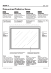
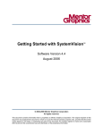
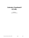
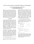
Help on H-Bridge SPICE Motor Controller
SystemVision Example:
H-Bridge SPICE Motor Controller
Copyright © Mentor Graphics Corporation 2003
All Rights Reserved.
This document contains information that is proprietary to Mentor Graphics Corporation.
The original recipient of this document may duplicate this document in whole or in part for
internal business purposes only, provided that this entire notice appears in all copies. In
duplicating any part of this document, the recipient agrees to make every reasonable effort to
prevent the unauthorized use and distribution of the proprietary information.
Copyright © Mentor Graphics Corporation 2004
1
Help on H-Bridge SPICE Motor Controller
H-Bridge SPICE Motor Controller
This help file discusses how to use SystemVision to simulate a simple H-Bridge Motor
Controller. This example combines SPICE models for the electronics with VHDL-AMS
models for the motor and loads. The ability to simulate these together is made possible by
SystemVision’s support for multiple industry standard languages.
The SystemVision project is named Beyond_SPICE. Contained in the project are several test
benches that illustrate how SystemVision uses VHDL-AMS to extend SPICE beyond its
inherent limitations for modeling mixed-technology systems. This help file will sequentially
walk you through each of these designs.
Getting Started
Users are encouraged to look through the following documents from the SystemVision
Help menu.
1. Help > SystemVision Help Topics
This is the main online help resource with hyperlinks. Topics include: Introduction to
SystemVision, The User Interface, SystemVision Commands, and “How do I …?” tips.
2. Help > SystemVision Online Manuals > Getting Started
The Getting Started tutorial is provided to acquaint users with SystemVision. It is
recommended that users run through this tutorial prior to running other examples.
3. Help > SystemVision Online Manuals > User’s Manual
The Users Manual is provided as a reference source for SystemVision. Detailed
explanations on tool usage are provided.
4. Help > SystemVision OnlineManuals > SystemVision Quick Reference Guide
This document should be printed and used as a reference for running SystemVision
examples.
5. Help > SystemVision Online Manuals > VHDL-AMS Quick Reference Guide
This VHDL-AMS reference succinctly reviews many VHDL-AMS language features. It
is intended for those users interested in creating/understanding VHDL-AMS models.
6. For specific information on the Waveform Viewer, select Help > Quick Start and
Help > Tutorial > Open Tutorial from the main Waveform Viewer window).
1.0
tb_hbridge_spice testbench
Description:
The design tb_hbridge_spice, shown in Figure 1, is an example of a typical hbridge driver
circuit modeled in SPICE. Voltage pulse sources are used as the forward and reverse
command signals and the motor load is approximated with a resister and inductor in series.
Copyright © Mentor Graphics Corporation 2004
2
Help on H-Bridge SPICE Motor Controller
Figure 1- tb_hbridge_spice schematic
Using SPICE Primitives in SystemVision
Although SystemVision may be known primarily as a VHDL-AMS simulator, is it also
capable of operating as a SPICE simulator. To do this, SystemVision can be configured
to run in what is called “SPICE-on-Top” mode. Here the top-level netlist is SPICE and
calls to models written in other languages (like VHDL-AMS) are done through an
instantiation of a SPICE “Y” element. To facilitate this, schematic symbols have been
created that reside in two symbol libraries:
1. SpicePrimitive: Symbols of basic SPICE passive elements (R,L,C), controlled
sources (E,F,G,H) and others.
2. SpiceSemiconductor: Symbols for the 4 basic semiconductor devices (D, Q,
M, J)
Using these symbols will automatically force a SPICE netlist to be created allowing the
user to operate in a familiar mode even when adding VHDL-AMS models.
Design Selection/Viewing/Editing
1. Make sure the Beyond_Spice project is loaded into SystemVision.
2. From the Project tab, click on Design Roots > tb_hbridge_spice to open the schematic.
Copyright © Mentor Graphics Corporation 2004
3
Help on H-Bridge SPICE Motor Controller
Accessing the Spice symbols
1. To access the SPICE symbols mentioned above, select Add > Component from the pulldown menu and scroll down the symbol library list as shown in Figure 2.
Figure 2 - Accessing SPICE Symbols
2. The schematic has already been created for you, so there is no need to place any
symbols.
Simulating the circuit
3. From the Pull-down menu, select Simulation > Simulate to invoke the Simulation Control
window (there is also a simulation icon available on the iconbar).
• The Simulations tab is for the basic settings and to enable/disable the desired
analyses. Enable the Time-Domain Analysis and set End Time to 1s.
• The Results tab allows you to select the signals for viewing. The default selection is
TopLevel Waveforms which will save all signals at the highest level of hierarchy. Since
this is a small design, All Signals was selected for convenience. You can also choose
Selected Waveforms and click on the browse button (…) to select individual signals.
• The Multi-Run tab is for performing parametric variations.
• The Advanced tab is used for advanced simulation settings (normally not required).
4. Click the OK button to run the simulation (the Output Window will display the simulation
progress and any error messages that may be issued).
Copyright © Mentor Graphics Corporation 2004
4
Help on H-Bridge SPICE Motor Controller
Viewing Results
5. The simulation results will automatically be loaded into the waveform viewer upon
completion of a successful simulation (if not, look in the Output Window for any error
messages).
6. Individual signals can be viewed by double-clicking with the LMB or by using the dragand-drop feature. You can also plot a signal from the schematic by selecting the desired
signal and using RMB > Plot Waveform. Use one of these methods to plot the signals
v_fcmd, v_rcmd and vl_1 which should appear as shown in Figure 3 below:
Figure 3 - tb_hbridge_spice signals
The forward and reverse command signals indicate the times the transistors are turned on,
and the signal vl_1 is the load voltage (with respect to ground). This is some good
information, but what we really want is the current through the load. It is possible to view
the currents through SPICE elements in SystemVision, but and extra step is required as
explained in the next section.
Plotting SPICE currents in SystemVision
Plotting currents through SPICE elements in SystemVision is currently not supported when
using the Simulation Control dialog. For this and other advanced commands, SystemVision
allows you to edit the simulation command file. This file gives you direct access to the
Copyright © Mentor Graphics Corporation 2004
5
Help on H-Bridge SPICE Motor Controller
simulation control language and provides an alternate method to running simulations that
you will find useful.
1. Select the simulation tab in the AddInTree window on the left-hand side of the
SystemVision interface.
2. Expand tb_hbridge_spice testbench to access the Experiment Files as in Figure 4 shown
below:
Figure 4 - Simulation Tab in SystemVision
3. Here an alternative experiment file has already been created for you (PlotCurrents.cmd).
4. Put your cursor over the PlotCurrents.cmd file and select RMB > Open in Text Editor to
view.
5. Note the line “.probe v i ” gives you access to the voltages and currents through all
elements.
6. The File > Save As … command from the pull-down can be used to create multiple
experiment files for a given design.
7. Put your cursor over the PlotCurrents.cmd file and select RMB > Simulate to run a
simulation using this command file.
8. Upon completion, the simulation results will again be loaded into the viewer. Select the
signal i(rload) and plot into the original graph window, replacing the vl_1 signal as shown
in Figure 5 below:
Copyright © Mentor Graphics Corporation 2004
6
Help on H-Bridge SPICE Motor Controller
Figure 5 - Simulation results with load current
9. Plot any other signals of interest.
2.0
tb_hbridge_spice_ams testbench
Description
The design tb_hbridge_spice_ams, shown in Figure 6, is a modified version of the previous
H-bridge circuit. The original transistor circuit implementation is still in tact, but the voltage
command signals have been replaced by digital (VHDL) stimulus and the simplified RL load
has been replaced by a VHDL-AMS DC motor model. The addition of these components
makes it a much more realistic system model. Using SystemVision, the power of VHDLAMS can be seamlessly incorporated to an existing SPICE circuit with no additional burden
on the end user.
Copyright © Mentor Graphics Corporation 2004
7
Help on H-Bridge SPICE Motor Controller
DC Motor
Rotational
Stop
Digital Command
Inputs
Moment of
Inertia
Figure 6 - tb_hbridge_spice_ams schematic
Design Selection/Viewing/Editing
1. Make sure the Beyond_Spice project is loaded into SystemVision.
2. From the Project tab, click on Design Roots > tb_hbridge_spice_ams to open the schematic.
3. Select the DC Motor Symbol and RMB > Push Language > VHDL to view the VHDL-AMS
model (repeat for other VHDL-AMS models as desired)
4. RMB > Edit Model Properties gives you access to the VHDL-AMS model properties.
Simulating the circuit
5. Return to the schematic and from the Pull-down menu, select Simulation > Simulate to
invoke the Simulation Control window (there is also a simulation icon available on the
iconbar).
6. The Simulations tab is for the basic settings and to enable/disable the desired analyses.
Enable the Time-Domain Analysis and set End Time to 1s.
• The Results tab allows you to select the signals for viewing. The default selection is
TopLevel Waveforms which will save all signals at the highest level of hierarchy. Since
this is a small design, All Signals was selected for convenience. You can also choose
Selected Waveforms and click on the browse button (…) to select individual signals.
• The Multi-Run tab is for performing parametric variations.
• The Advanced tab is used for advanced simulation settings (normally not required).
7. Click the OK button to run the simulation (the Output Window will display the simulation
progress and any error messages that may be issued).
Copyright © Mentor Graphics Corporation 2004
8
Help on H-Bridge SPICE Motor Controller
Viewing Results
8. The simulation results will automatically be loaded into the waveform viewer upon
completion of a successful simulation (if not, look in the Output Window for any error
messages). Individual signals can be viewed by double-clicking with the LMB or by using
the drag-and-drop feature. You can also plot a signal from the schematic by selecting the
desired signal and using RMB > Plot Waveform. Use one of these methods to plot the
digital command signals fcmd and rcmd indicated by the
symbol next to the
waveform name.
9. Next plot the motor current ydcmotor1/i. Notice the effect of the back-emf voltage as
modeled in the motor equations.
10. Plot the signal position. This is the position of the motor shaft over time. Notice that
the motor does not return to its original position due to the short length of the reverse
command signal.
11. The desired waveforms are shown in Figure 7 below:
Figure 7 - Motor current and position
Parametric Sweeps
This example illustrates that by adding VHDL-AMS models to a SPICE circuit, we are able
to easily create a mixed-technology system model. Using this model we are not limited to
the electrical domain. For example, we are able to view the motor shaft angular position and
looks at the effect of the back-emf voltage generated by the motor.
Copyright © Mentor Graphics Corporation 2004
9
Help on H-Bridge SPICE Motor Controller
The next step is to look at this system as a whole and examine the effects of the component
parameters on the motor position. We will do this by sweeping a parameter (motor winding
resistance) over a specified range.
1. Return to the tb_hbridge_spice_ams schematic and from the pull-down menu, select
Simulation > Simulate to invoke the Simulation Control window
2. Select the Multi-Run tab as shown below:
3. Change the Parameter Change Type to Sweep Values
4. Click on the Parameter Edit button to invoke the Sweep Parameter dialog:
5. Click on the browse button (…) to invoke the Select Parameter dialog:
Copyright © Mentor Graphics Corporation 2004
10
Help on H-Bridge SPICE Motor Controller
6.
7.
8.
9.
Select the VHDL Instance Parameter ydcmotor1.r_wind as shown above and click OK.
Set the Sweep Type to List and the Sweep List to 50.0 100.0 200.0.
Click OK to save settings and run the simulation.
Plot the digital command signals (fcmd and rcmd) along with the motor position as
shown in Figure 8 below:
Figure 8 - Parametric Sweep Results
Copyright © Mentor Graphics Corporation 2004
11
Help on H-Bridge SPICE Motor Controller
Performing Measurements (optional)
As expected, these results show that the winding resistance has a significant effect on the
final angular position. SystemVision allows you to quantify relationships between system
performance and component parameters by performing measurements on the simulation
results. In this section we will re-run the previous analysis with additional sweep values.
This will take a bit longer to run, but the extra data generated will allow us to create
meaningful correlation plots.
1. Re-invoke the Simulation Control dialog and click on the Multi-Run tab
2. Click the Parameter Edit button and modify the existing fields as follows:
Parameter: E(ydcmotor1,r_wind) (unchanged from previous analysis)
Sweep Type: Increment
Sweep Start: 10.0
Sweep Stop: 100.0
Sweep Increment: 10.0
3. Plot the signal position into a new graph
4. Click the Add Cursor button
below:
to place two cursors (C1 and C2) as shown in Figure 9
Figure 9 - Parametric Sweep Results with Measurements
and fill in the dialog as shown below to annotate the
5. Click the Measurement Tool icon
risetime measurement results to the graph:
Copyright © Mentor Graphics Corporation 2004
12
Help on H-Bridge SPICE Motor Controller
6. In the Measurement Tool, select the Plot New Waveform … option and re-apply to create a
plot of risetime vs. motor winding resistance.
7. Repeat steps 5 and 6 above for falltime.
8. The results are shown in Figure 10 below:
Figure 10 - Correlation Plots
Copyright © Mentor Graphics Corporation 2004
13
Help on H-Bridge SPICE Motor Controller
Figure 10 clearly shows the effect the value the motor winding resistance has on the shaft
position when used with the H-bridge driver circuit. This is a simple example of how
SystemVision can be used to turn simulation data into engineering information that can be
used to help improve a mixed-technology system design.
3.0
tb_motor_drive_hier testbench
Description
The design tb_motor_drive_hier shown in Figure 11 is identical to the previous design
except that the H-bridge circuit has been imported as a SPICE netlist using the symbol
HBRIDGE1. Using SystemVision any Berkeley-compatible SPICE netlist can be imported
into SystemVision and directly connected to VHDL-AMS component models.
Figure 11 - Motor Drive System with SPICE netlist for H-Bridge Circuit
Design Selection/Viewing/Editing
1. Make sure the Beyond_Spice project is loaded into SystemVision.
2. From the Project tab, click on Design Roots > tb_motor_drive_hier to open the schematic
3. Select the HBRIDGE1 symbol and RMB > Push Language->SPICE to reveal the SPICE
netlist shown in Figure 12 below:
Copyright © Mentor Graphics Corporation 2004
14
Help on H-Bridge SPICE Motor Controller
* Definition for project MOTOR_DRIVE
.SUBCKT MOTOR_DRIVE REF VCC V_FWD V_HIGH V_LOW V_REV
*
Q1 VCC V_FWD V_HIGH Q2N3904
Q2 V_HIGH V_REV REF Q2N3904
Q3 VCC V_REV V_LOW Q2N3904
Q4 V_LOW V_FWD REF Q2N3904
D1 V_HIGH VCC D1N914
D2 REF V_HIGH D1N914
D3 V_LOW VCC D1N914
D4 REF V_LOW D1N914
* CROSS-REFERENCE 1
* GND = 0
.model D1N914 D(Is=0.1p Rs=16 CJO=2p Tt=12n Bv=100 Ibv=0.1p)
*
85-??-??
Original library
.model Q2N3904 NPN(Is=6.734f Xti=3 Eg=1.11 Vaf=74.03 Bf=416.4 Ne=1.259
+ Ise=6.734f Ikf=66.78m Xtb=1.5 Br=.7371 Nc=2 Isc=0 Ikr=0 Rc=1 Cjc=3.638p
+ Mjc=.3085 Vjc=.75 Fc=.5 Cje=4.493p Mje=.2593 Vje=.75 Tr=239.5n Tf=301.2p
+ Itf=.4 Vtf=4 Xtf=2 Rb=10)
*
Fairchild
pid=23
case=TO92
*
88-09-08 bam
creation
.ENDS
Figure 12 - H-Bridge SPICE Netlist
Simulating the circuit
Repeat the simulation steps in Section 2.0 above to verify that the functionality is
identical.
This concludes the tutorial. For more information on using SPICE within SystemVision
consult the following references accessible from the Help pulldown menu in
SystemVision:
1. Help > SystemVision Help Topics > How Do I …? > Files and Projects
a. Import a SPICE subcircuit
2. Help > SystemVision Help Topics > How Do I …? > Models, Libraries, and Schematics
a. Add and Use a SPICE Library
b. Place a SPICE component or subcircuit in my design
c. Create a symbol for SPICE subcircuit file
d. Use a FAS (SPICE) macromodel
3. Help > SystemVision Help Topics > How Do I …? > Simulation
a. Simulate a single SPICE component or design
4. Help > SystemVision Help Topics > Reference Information > SPICE Usage
5. Help > SystemVision On-Line Manuals > User’s Manual
a. Appendix A – Using Spice with SystemVision
Copyright © Mentor Graphics Corporation 2004
15
Help on H-Bridge SPICE Motor Controller
Copyright © Mentor Graphics Corporation 2004
16