1
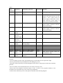
Table 1
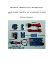
PCB
indications
Functions
Equipment connected
Signal mode
Remarks
BAT
12V power or 3S lipo
battery
DC
Working voltage 6-14V
JP
Main board
battery
Jumper
V_OUT
Video output
Video frequency
NTSC/PAL
V_IN
Video input
Camera
NTSC/PAL
AUX_Out
Rudder
output
Aileron
steering
engine output
Elevator
steering
engine output
Throttle
output
Aileron input
Elevator input
Throttle input
Rudder input
Pilot
mode
shift
AIL_OUT
ELE_Out
THO_Out
AIL_In
ELE_In
THO_In
AUX_In
MOD_In
SCR_In
OSD display
switch
If only the power is 12V or 3S Lipo
battery, the main board can use the
power. 1 and 2 short circuit for
power supply of main board, 2 and 3
short circuit for power supply of
battery power and the main board
Automatic detection of video signal,
power supply consistent with the
main board voltage
Automatic detection of video signal,
power supply consistent with the
main board voltage
PWM
Elevator steering engine
PWM
Speed regulator or throttle
steering engine
Receiver aileron channel
Receiver elevator channel
Receiver throttle channel
Receiver rudder channel
Receiver knob channel
PWM
Receiver
channel
PWM
knob
switch
PWM
PWM
PWM
PWM
PWM
Shift between manual control, PA,
AUTOPILOT, RTH
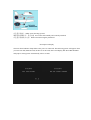
Cautions:
1. Never touch the pressure sensor with anything, keep it clean and free from explosion to light.
2. Never pressurize the air speed indicator in case damage may occur.
3. Keep the circuit board away from electromagnetic field, such as video projector and remote controller
protector.
4. Never touch the circuit board with metal in case short circuit may occur.
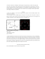
5. Keep away from propeller movement range (at least 1.5 times of the propeller diameter to the
assistant) in case deviations may occur to the air speed indicator.
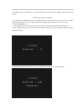
6. Please fit the infrared ray sensor to the plain as indicated in the following diagram.