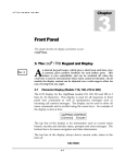
1
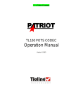
Prima LT
U S E R S
3
Chapter
G U I D E
Front Panel
This chapter describes the displays and buttons on your Prima LT
3 The Prima LT Keypad and Display
A
n internal keypad beeper, which gives a short beep each time a
key is pressed, gives positive feedback for each button press.
This feature is user controllable, and can be switched off when
the Prima LT is used in environments where noise cannot be
tolerated. In addition, the display contrast can be adjusted over a wide
range to allow for easy viewing from any angle.
3.1 Character Display
The 2 lines by 16 character LCD display for the Prima LT serves two
functions, setup and system status. This setup display is used for menu
navigation and for selecting responses to front panel user prompts.
Although only 16 characters wide, the dual-purpose display can be
used to show all menu commands and is scrolled using the cursor keys.
An example of the display is shown here:
PRIMA LT
[algorithm]
1.xx
loop
The top line of the display is for information such as current menu
branch, encoder and decoder status, prompts and error messages. The
bottom line is for menu navigation and other information. When at the
top of the menu tree, this line will show the software version of the
Prima LT.
Encoder and decoder status displays can be shown at any time by pressing
the E STAT or D STAT buttons. An example of the encoder status display is
shown here:
3-1
Prima LT
U S E R S
G U I D E
ENC MPEGL2 48KHz
00:00 LB 128K JS
The display shows the encoder configuration including algorithm, bit
and sample rate and connect time (if connected) or loopback state, and
is interpreted as follows:
Field
Description
Range
1
ENC - This indicated
that the Encoder status
display is shown
ENC
2
Algorithm
MPEGL2, MPEGL3, G.722, CCSO or
CCSN
3
Sample rate
16, 24, 32 or 48 kHz
The bottom line shows additional encoder information:
Field
Description
Range
1
Connect time
MM:SS or HH:MM format, as appropriate,
colon will flash when connected.
2
Loopback state
LB = loopback ON, blank = loopback OFF
3
Bit Rate
Selected encoder bit rate, in kb/s
4
Algorithm mode
M = Mono, DM = Dual Mono, FS = Full
Stereo, JS = Joint Stereo
An example of the decoder status display is shown here:
DEC MPEGL2 48KHz
00:00 IND 128 JS
The display shows the decoder configuration including algorithm, bit
and sample rate and connect time (if connected) and independent
mode, and is interpreted as follows:
Field
Description
Range
1
DEC - This indicated
that the Encoder status
display is shown
DEC
2
Algorithm
MPEGL2, MPEGL3, G.722, CCSO or
CCSN
3
Sample rate
16, 24, 32 or 48 kHz
3-2
Prima LT
U S E R S
G U I D E
The bottom line shows additional encoder information:
Field
Description
Range
1
Connect time
MM:SS or HH:MM format, as appropriate,
colon will flash when connected.
2
Independent mode IND = decoder independent, blank =
decoder not independent
3
Bit Rate
Selected decoder bit rate, in kb/s
4
Algorithm mode
M = Mono, DM = Dual Mono, FS = Full
Stereo, JS = Joint Stereo
3.2 Front Panel Controls
Figure 3-1 Prima LT keypad
3.2.1 Cursor Keys
The 4 keys arranged in a cloverleaf are used to control the cursor. They
are:
UP ARROW
LEFT ARROW
RIGHT ARROW
ENTER
The up arrow key is used to move up the menu tree. This key is also
used on power-up to force entry into the ROM boot mode.
The left and right arrow keys are used to move to the left and right in
the menu tree.
3-3
Prima LT
U S E R S
G U I D E
The ENTER key is used to bring you down to the next level or execute
the menu tree entry enclosed within the square brackets ( [ ] ).
3.2.2 Alphanumeric Keypad
The alphanumeric keypad is used to enter all information required for
the execution of commands, as well as for dialing. Besides digits 0-9,
the entire 26-letter alphabet and limited punctuation is represented by
only 12 keys. By repeatedly pressing a key, different characters are
displayed, and that character is locked in when the cursor keys are used
to scroll to the next character. Once the character string has been
entered, the ENTER key enters or executes the string or dials the number.
Different commands or function modes enable different characters on
these keys. For example, dialing commands enable only the numeric
selections for these keys. When Prima Logic Language commands are
entered all key characters are enabled. By depressing the 2 key
repeatedly, the A, B and C characters are displayed. When such multicharacter modes are enabled, the left and right arrow keys are used to
move to the left and right on the current line. The ENTER key is used to
accept the entire entry.
3.2.3 Dial Setup Keys
The four keys below the DIAL label are used for Quick Configurations
and for dialing when using an internal terminal adapter. They are:
DIAL
SDIAL
SDSET
HANGUP
The DI A L key allows direct manual dialing, of one or both of the ISDN
‘B’ channels when an internal terminal adapter is used. Before dialing
can be attempted for the first time or after a factory default reset, the
terminal adapter Digital Interface (DIF) must be defined by using the
CIF command or from the keypad (see Chapter 5). The DIF must be a
Terminal Adapter (TA) type of Digital Interface Module (DIM) such as
a TA301. You cannot use the Prima LT dial keypad to dial through an
external terminal adapter.
Pressing the DI A L key starts the dialing sequence. The LCD display will
prompt the user for the line (‘B’ channel) to dial and the telephone
number(s). The last numbers dialed on all lines are saved as long as
power is maintained. To dial a different number, simply overwrite the
3-4
Prima LT
U S E R S
G U I D E
previous number. Once the ENTER key is pressed confirming the entry
of the phone number, the dialing operation begins. The
LCD display will indicate that the Prima LT is dialing. When the LCD
display will indicate the line connects and the DIF LED lights when the
connection is established.
The SDIAL key is used to speed dial a destination or to load a QuickConfiguration. After depressing SDIAL , the LCD screen prompts for
the 1, 2, or 3 digit speed dial number, representing which of the 256
possible Speed Dial entries to dial. Pressing the ENTER key causes the
Prima LT to configure and/or dial. See the CSD command in the
CDQPrima Remote Control Manual, available from MUSICAM USA or
on-line at www.musicamusa.com, for details on the required
parameters.
The SDSET key is used to set up a Speed Dial entry and maintain the
Speed Dial directory. Pressing this key brings up a sub menu with
commands that allow you to save, recall, view, edit and delete existing
entries, and to add new entries. Selecting <Add entry> produces a
series of prompts on the LCD display to enter the speed dial
parameters. The parameters to be entered are described in later
chapters of this document, and include bit rate, sample rate, algorithm,
mode, etc.
The HANGUP key is used to terminate a connection made using the DIAL
or SDIAL keys. Pressing this key allows any or all lines to be dropped.
See the CHU command in the CDQPrima Remote Control Manual.
3.2.4 Status And Function Keys
The E STAT and D STAT buttons display the encoder and decoder status.
All important parameters are shown, including bit and sample rate,
algorithm and mode, loopback state and connect time. Pressing the up
arrow é key returns the display to the normal menu mode.
The two function keys, F1 and F2 , can be programmed to execute any
Prima Logic Language or remote control command. For example, you
can program a function key for one button speed dialing. If these keys
have not been programmed, pressing one will bring you directly to the
key programming menu.
3-5
Prima LT
U S E R S
G U I D E
3.3 Front Panel Status Indicators
The eight status LEDs on the front panel give visual indication of the
codec status. The top four LEDs show audio level for left and right
channels, normal and clip. Under normal operation, the green NORM
LED should illuminate and the red CLIP LED should not.
The FRAMED LED indicates that the decoder is framed to the far-end
encoder and must also be illuminated for proper operation when
connected to another codec.
The red BER LED will flash whenever there is a bit error in the
transmission system. There may also be relay chatter whenever this
LED illuminates.
This indicates that there is trouble with the
transmission system, and your service provider should be contacted.
The DIF1 and DIF2 LEDs indicate the connect state of lines 1 and 2. Off
means not connected, on indicates connected. When using some nonTA digital interface modules, these LEDs may be on continually
3-6