1
Embarc Information Technology (Pvt) Ltd.
Copyright © 15th October, 2013
All rights reserved
Notice
This manual, as well as the software described in it, is furnished under license granted by Embarc Information
Technology (Pvt) Ltd. to authorized clients and may be used only in accordance with the terms of license granted.
The content of this manual is furnished for informational use only, is subject to change without notice, and
should not be construed as a commitment by Embarc Information Technology (Pvt) Ltd. While every care has
been taken for the correctness of the information, Embarc Information Technology (Pvt) Ltd. assumes no
responsibility or liability for any inaccuracies that may have inadvertently crept in this manual.
Embarc Information Technology (Pvt) Ltd. reserves right to make changes to specifications/features/utilities at any
time and without notice. The information furnished by Embarc Information Technology (Pvt) Ltd. in this manual is
believed to be accurate and reliable. Embarc Information Technology (Pvt) Ltd. assumes no responsibility for its use,
or for infringements of patents or other rights of third parties resulting from its use. No license will be granted
under any patents or patent rights owned by Embarc Information Technology (Pvt) Ltd.
Please check up for updated version of user manual at: http://www.findnsecure.com/downloads.html
Use of Google API
Find’n’Secure software uses Google API. Use of Google API is governed by the Terms and Conditions as described
in the Google Maps API signup page (https://developers.google.com/maps/documentation/business)
i|Page
CONTENTS
Introduction ................................................................................................................ 1
GPS tracking system ..................................................................................................................... 1
GPS Tracking Unit.......................................................................................................................... 1
Common uses................................................................................................................................... 2
Find’n’Secure® ................................................................................................................................ 2
Administration ...........................................................................................................3
Administrator Home ..................................................................................................................... 3
System Information ...................................................................................................................... 5
Trackers Information ................................................................................................................... 6
Backup History ................................................................................................................................ 6
Trackers Management ................................................................................................................. 6
Device ID and IMEI Number ..................................................................................................... 10
Remove Tracker(s) ...................................................................................................................... 10
Create Tracker Copy .................................................................................................................. 10
Trackers Debugger ...................................................................................................................... 10
Filters................................................................................................................................................ 11
Trackers List .................................................................................................................................. 13
Group View ..................................................................................................................................... 14
Trackers Clusters ......................................................................................................................... 15
Snail Track View .......................................................................................................................... 18
History .............................................................................................................................................. 24
Controls............................................................................................................................................ 31
Tracker Details ............................................................................................................................. 32
Events ............................................................................................................................................... 37
Full Screen Map View ................................................................................................................. 38
Quick POI ......................................................................................................................................... 39
Map Options ................................................................................................................................... 39
ii | P a g e
Debug Log ....................................................................................................................................... 41
Edit Tracker ................................................................................................................................... 41
Add/Remove POI .......................................................................................................................... 41
Add POI ............................................................................................................................................ 42
Modify POI ....................................................................................................................................... 43
Remove POI .................................................................................................................................... 44
Upload POI List ............................................................................................................................. 44
Users Management ...................................................................................................................... 44
Add Account ................................................................................................................................... 46
Modify Account ............................................................................................................................. 48
Remove Account .......................................................................................................................... 49
Blacklist Account ......................................................................................................................... 49
Remove from blacklist .............................................................................................................. 49
Database Management .............................................................................................................. 49
Fuel Sensor ..................................................................................................................................... 51
Temperature Sensor ................................................................................................................... 52
Global Settings ............................................................................................................................. 52
Modify Password........................................................................................................................... 53
Restore Database from Backup ............................................................................................. 53
Advanced Tools for Administrators ..................................................................... 54
MySQL Administrator Utility ................................................................................................... 54
tcpdump .......................................................................................................................................... 55
Wireshark ........................................................................................................................................ 56
Capturing with tcpdump for viewing with Wireshark ................................................. 57
Setting up MySQL mirror .......................................................................................................... 57
Settings for MAIN ......................................................................................................................... 58
Steps for MIRROR ......................................................................................................................... 59
iii | P a g e
iv | P a g e
INTRODUCTION
GPS TRACKING SYSTEM
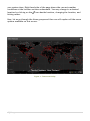
The Global Positioning System (GPS) is a satellite-based navigation system
made up of a network of 24 satellites placed into orbit by the U.S. Department
of Defense. GPS was originally intended for military applications, but in the
1980s, the US government made the system available for civilian use free of
cost. Initially the highest quality signal was reserved for military use, while the
signal available for civilian use was intentionally degraded ("Selective
Availability"). Selective Availability was ended in 2000, improving the precision
of civilian GPS from about 100m to about 20m. GPS works in any weather
conditions, anywhere in the world, 24 hours a day.
GPS satellites circle the earth twice daily and transmit signal information. GPS
receivers use the information to calculate the user's location by the method of
triangulation. Basically, the GPS receiver compares the time a signal was
transmitted by a satellite with the time it was received. The time difference
tells the GPS receiver how far away the satellite is. The receiver must lock on
to the signal of at least three satellites to calculate a 2-D position, the
latitudinal and longitudinal position, and track movement. Using four or more
satellites, the receiver can determine the user's 3-D position, the latitude,
longitude, and altitude. Once the position has been determined, the GPS unit
can calculate other information such as speed, track, trip distance, bearing and
more.
GPS TRACKING UNIT
A GPS tracking unit is a device that uses the Global Positioning System to
determine the precise location of a vehicle, person, or any other asset to which
it is attached and to record the position of the asset at regular intervals. The
recorded location data can be stored within the tracking unit, or it may be
transmitted to a central location data base, or internet-connected computer,
using a cellular (GSM/CDMA), radio, or satellite modem embedded in the unit.
This allows the asset's location to be displayed against a map backdrop either
in real-time or when analyzing the track later, using customized software.
1|Page
COMMON USES
Most common application of GPS tracking system is applied for tracking of
moving objects, such as, vehicles. Vehicle tracking systems are commonly used
by fleet operators for fleet management functions such as routing, dispatch,
on-board information and security. Other applications include monitoring
driving behavior, such as an employer of an employee, or a parent with a teen
driver. Vehicle tracking systems are also popular in consumer vehicles as a
theft prevention and retrieval device. Police can simply see the vehicle in realtime over the tracking system and locate the stolen vehicle.
Remote controlling of the vehicle through GPS tracking system is also possible.
In such a case owner of the vehicle can give commands to the tracking unit for
various operations like blocking the engine or cutting fuel supply to engine etc.
GPS personal tracking system is commonly used for tracking of persons, pets
etc. You can keep track of your loved ones in real time using a completely
accurate and totally reliable GPS software package via the internet so you
know exactly where your kids, parents, pets, asset are at any given point in
time.
FIND’N’SECURE ®
Embarc Information Technology Pvt. Ltd., a leading provider of GPS tracking
and security system from India, aims at offering innovative and cost effective
tracking and security solutions comprising of hardware as well as software.
GPS tracking technology is best suited for fleet management. It is a unique way
for companies and individuals to monitor and control their cars, jeeps, trucks
and other vehicles to their precise details by sitting in the office.
Find’n’Secure® GPS tracking system will enable you to monitor the movements
of your employees, drivers, vehicles or any other asset accurately. With
Find’n’Secure® vehicle tracking system in your company's fleet of vehicles, you
will find a smart way of fleet management by tracking your vehicles.
Whether you own one truck or a fleet of thousands of vehicles, our highly
skilled GPS fleet consultants will assist you in selecting the right type of vehicle
tracking system that will give an edge to your company.
2|Page
CHAPTER 1
ADMINISTRATION
In this chapter we will take a walk-through of Find’n’Secure® from an
administrator’s point of view. We will start with the login and then proceed to
all the detailed steps required for proper functioning of the software.
Newly installed software on the server is by default provided with an
administrator account with the username ‘admin’ and password ‘admin’. It is
important for you to change the password of the admin account on first login;
otherwise it may result in a security breach for your software.
In this Chapter as well as the Chapters that follow, we shall be making use of
the domain ‘trackv4.findnsecure.com’, you should replace this domain with
your own domain to perform the exact steps.
Open web-browser and go to the URL http://trackv4.findnsecure.com
Enter username admin
Enter Password admin
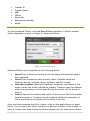
Select your preferred language
Select your preferred time zone
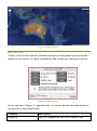
Time zone GUI utility with magnetic mouse pointer helps you in fast
selection of the time zone as shown in Figure 1: Time zone Utility
Click Sign In
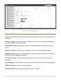
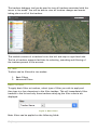
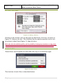
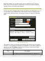
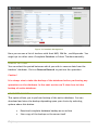
ADMINISTRATOR HOME
Once all the above steps have been performed, you will be presented with the
homepage for administrator panel, as shown in Figure 2: Administrator Home
Administrator home comprises of three groups, named: System Information,
Trackers Information, and Backup History. Apart from these groups it has a
navigation menu and a few other additional details. The top-left corner of the
page displays the last login time for the administrator user. In the center of the
page, current time on your system is shown. There will be a warning shown, if
your computer time is incorrect, in which case you should immediately correct
3|Page
your system time. Right hand side of the page shows the current weather
conditions at the location written underneath. You may change to a desired
location by clicking on the
icon beside location, changing the location, and
hitting return.
Now, let us go through the three groups and then we will explore all the menu
options available on this screen.
Figure 1: Time zone Utility
4|Page
Figure 2: Administrator Home
SYSTEM INFORMATION
System Information shows detailed information about the server hardware and
software.
Processor type: Processor name, model number, clock frequency and number
of cores present in the processor.
Operating System: Name and version of operating system installed on the
server.
Software version: The current version of Find’n’Secure software installer.
Database name: Name of the database in which location and event records for
Find’n’Secure software are stored.
Location Records: The number of location records currently stored in the
database.
Event Records: The number of event records currently stored in the database.
Time on system: Current time on system.
System uptime: Time elapsed after last server restart.
5|Page
Mapping Service: Current default mapping service. The mapping service can be
changed from Google Maps (default) to OpenStreet Maps, using the Change
button beside the current mapping service.
These statistics come in handy, when analyzing database load on the server and
provides an overview of database health to the administrator.
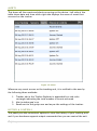
TRACKERS INFORMATION
This group consists of three graphs, each of which provides details on the
number of trackers and licenses issued on the server.
Total Trackers: The total number of trackers currently associated with the
server. Beside the total number of trackers, the total number of licenses
available is also mentioned. If you need more detailed information about the
trackers working on the server, you can click on the graph, drawn for total
trackers, which in turn redirects to a new page showing all trackers, graphically
organized according to tracker model.
Working Trackers: Total number of working trackers, i.e. trackers which are
sending data to the server.
Non-working Trackers: Total number of non-working trackers. These trackers
are not sending data to the server.
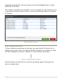
BACKUP HISTORY
Whenever database backup is performed using the software, its log is created
and displayed in this table. This is helpful in recalling when last backup of the
database was performed.
You’ll be able to see different signs in ‘Downloaded’ and ‘Stored on Server’
column, depending upon whether the database backup was downloaded or
stored on server or both. It is recommended to always download the database
backup.
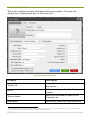
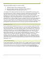
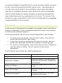
TRACKERS MANAGEMENT
In this section we’ll learn how to add/remove/modify trackers on your server.
This page is divided into two sections, left hand side of the page lists all
existing trackers associated with the server and right hand side presents a
Tracker Card to add new trackers and modify existing ones. Throughout this
manual you’ll note that we have followed a similar two column layout for
managing existing information and adding new data.
6|Page
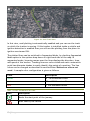
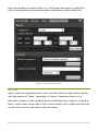
Figure 3: Trackers Management
If you have existing trackers associated with your server and wish to modify one
of those, click on that tracker row to fill up all related information in the right
hand side card. Various filter options are available to find a tracker in the list.
You may wish to filter trackers using Tracker ID, Tracker Name, IMEI, SIM
Number, Users, and Keywords. To apply a filter, select an appropriate filter
from the drop down list and then start typing your filter criteria in the text box
beside it. You’ll see the list filter out instantly.
Once you have selected an existing tracker or are willing to create a new one,
you may proceed to the right section of the page ‘Tracker Card’. It is important
to fill up this form with careful understanding otherwise the server will not be
able to identify your tracking devices and you will not be able to view trackers
reporting on the server. There are many debugging tools which may be used for
troubleshooting in case you don’t see data on your server; we will visit them at
the end of this chapter to help you in resolving issues.
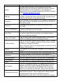
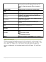
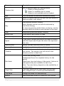
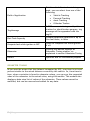
Field Name
Description
Tracker ID
Software uses Device ID or IMEI number to identify
device and perform related tasks. Device ID is always a
unique number on the server.
Custom ID: In certain circumstances you might need to
use a custom device ID, such as, adding an already
configured unit
Tracker Name
Name by which the tracking device is represented when
7|Page
the user logs in to the software
Model
Various make/models of the tracking devices are
supported by the software. Select the correct type as
per the tracker to be configured. You can get an
updated list of the trackers supported by Find’n’Secure®
from [email protected]
IMEI No.
IMEI number provided with the tracking device. This
number is provided at the time of device purchase and
may also be written on the device itself.
Serial No.
Serial Number of the tracker. This number is provided at
the time of device purchase and may also be written on
the device itself.
Protocol
Communication protocol on which this device is set
TCP/UDP
Date of Installation
Date on which this device is being installed into the
vehicle or handed over to the user.
Icon Text
The tracking icon can have a custom text, if required. If
no value is specified the trackers are marked using a
default numbering scheme
Date of Purchase
Date on which the tracker was purchased. This can be
useful in keeping track of warranty provided.
Tracker Expiry
Date on which the tracker should expire. After a tracker
expires, it is not visible anywhere in User Panel, except
on the list of expired trackers.
Note: The user will receive appropriate e-mails notifying
expiry of the tracker
SIM No.
The number of the SIM card, installed in the tracking
device
SIM Provider
Name of the service provider which issued the SIM card
SIM Serial
The serial number of the SIM card, this number is
provided by the service provider at the time of purchase
SIM Valid Up to
Date of validation expiry of the SIM card, if applicable
SIM Package
The package that might be applicable on the SIM card
Email
All alerts from the tracker will be sent to this email ID
Fuel Sensor
Click on ‘Configure Sensors…’ to enable up to five fuel
sensors. Each fuel sensor should be associated to an
input on the device and a fuel profile (we’ll visit the
section on creating fuel profiles, later in this manual)
Temperature Sensor
Click on ‘Configure Sensors…’ to enable up to five
temperature sensors. Each temperature sensor should
be associated to an input on the device and a
temperature profile (we’ll visit the section on creating
8|Page
temperature profiles, later in this manual)
Monitoring Center
Select the name of Monitoring Centre, if applicable.
MC Account No.
Specify the account number of Monitoring Centre, if
applicable
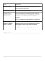
Features
You must enable the features that will be provided
along with this device to enable software to recognize
the inputs and process them accordingly.
RFID: Enable/Disable the use of RFID
CANBUS: Enable/Disable the use of CANBUS
Private/Public Sensor: Enable/Disable Private/Public
use
Weight Sensor: Mark if you need to use a weight sensor
with this device.
Driver Identification: Check to enable driver
identification. Please note, there must be an iButton or
RFID associated with the tracker, to use this feature.
SOS Button: Check if an SOS Button is required to be
used with this device.
Engine Immobilizer: Check to use an engine
immobilizer.
Ignition Sensor: Check if ignition sensor is provided.
Note, please do not check this feature, if ignition wire is
not connected properly or not connected at all.
Doors Sensors: Check to use doors sensor with this
device.
Dual Engine: Check to use dual engine. Specify the
device input on which second engine is connected.
Fuel Consumption Sensor: Check to use fuel
consumption sensor.
Odometer: Check to use and specify current value of
odometer in the vehicle.
SMS Limit: Specify the maximum number of SMS
messages that can be sent per month for this device. ‘0’
for unlimited.
Email Limit: Specify the maximum number of Email
messages that can be sent daily for this device. ‘0’ for
unlimited.
Reset SMS: Reset the SMS counter to the value specified
in the SMS Limit field.
Reset Email: Reset the Email counter to the value
specified in the Email Limit field.
Remarks
Specify additional remarks for this tracker
Search Keywords
Type in a few words which will uniquely identify this
9|Page
tracker, while searching at various locations in the
Find’n’Secure software.
Once the form has been filled up completely; click on ‘Save’ button to add
tracking device to the software. The tracker will be added to the list on the
left hand side, immediately.
DEVICE ID AND IMEI NUMBER
In the previous section we have seen creation of basic accounts and adding
tracking units. Adding a new tracker to the software depends on the type of
the hardware you have purchased and basic requirements of that tracker. Some
trackers are solely configured using the device ID such as FS-41 whereas some
trackers are configured using their IMEI numbers such as belonging to the group
FS-2x units. Each tracking unit is accompanied with an instruction manual
which guides you how to setup the unit with the software. It is possible to
make use of the hybrid collection of trackers with the software. It is very
important to set the tracking unit properly in order to allow the software to
recognize the hardware units correctly. In case you are unable to configure the
units or confused about the hardware, you can always get in touch with our
customer support team which will guide you on specific hardware models.
REMOVE TRACKER(S)
If you do not wish to use a tracker(s) anymore, you may completely remove
them from the server. To remove tracker(s), select a single tracker or multiple
trackers from the list of existing trackers and click on the ‘Remove’ button on
bottom left.
Caution! Removing trackers from the server will destroy all data present in
the database and this is an irreversible process.
CREATE TRACKER COPY
As the name of this option suggest it creates a new tracker with identical
information as the selected tracker. To copy a tracker select a tracker, from
the list of existing trackers and click the ‘Copy’ button on bottom left.
After you have added/removed/modified a tracker, you can click the ‘Finish’
button to go back to Administrator Home page.
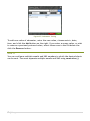
TRACKERS DEBUGGER
10 | P a g e
The trackers debugger tool can be used to view all trackers associated with the
server in live mode. You will be able to view all location changes and events
taking place on all of the trackers.
This module consists of a trackers list on the left and map on right hand side.
The list of trackers supports facilities for selecting, searching and filtering of
the trackers present in the account.
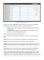
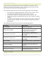
FILTERS
Trackers can be filtered in two modes:
1. Basic Filters
2. Advanced Filters
BASIC FILTERS
To apply basic filter on trackers, select type of filter you wish to apply and
then type in a few characters in the filter textbox. This will immediately filter
trackers in the list and only those trackers satisfying the filter criteria are
displayed.
Figure 4: Basic Filters
Basic filters can be applied on the following fields:
11 | P a g e
Tracker ID
Tracker Name
IMEI
SIM No.
Keywords
Registration Number
Model
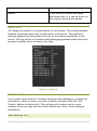
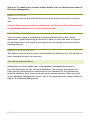
ADVANCED FILTERS
To view Advanced Filters, click the More Filters checkbox. A Filters window
will be displayed, as show in Figure 5: Advanced Filters
Figure 5: Advanced Filters
Advanced Filters can be applied on the following fields:
Speed Filter trackers according to the minimum and maximum speed
limit specified.
Status Filter trackers by their current status. Possible states are
Working, Moving, Stopped, Idling, No Data, and GPS Invalid.
Latitude/Longitude Specify the latitude, longitude, and radius of the
area in which the tracker should be present. Trackers near this address
within the proximity of circle specified by the radius will be shown in
the list.
Address Specify the address and radius of the area in which the tracker
should be present. Trackers near this address within the proximity of
circle specified by the radius will be shown in the list.
Once you have prepared the filter criteria, click on the apply button to apply
filters. You can move the filters window to a desired location on the screen, or
close it. Please note that closing the filters window will not remove the filters
12 | P a g e
applied. To remove filters, uncheck the More Filters checkbox, as shown in
Figure 6: More Filters
Figure 6: More Filters
TRACKERS LIST
Tracker Explorer shows the list of the trackers which you have installed in
various vehicles or name of people holding the personal trackers or for
whatever reason you is using the trackers.
Figure 7: Tracker in Trackers List
Figure 7: Tracker in Trackers List shows a tracker in trackers list. Each tracker
has a map placement checkbox, Tracker Name, Information, and events
number. When the map placement checkbox is checked the tracker is displayed
on the map otherwise it is only displayed in the list and events number is
updated each time an event occurs. Every tracker is assigned a unique number
e.g. 0000 in Figure 7: Tracker in Trackers List. This number is useful while
identifying the tracker when multiple tracker icons are displayed. These
tracker icons can also use a Custom Icon Text, which can be changed only by
the Administrator.
COLOR OF A TRACKERS’ ICON
The color of tracker icon determines the current status of the tracker. Possible
states for status of a tracker are:
Color
Description
Tracker is currently moving
Tracker is stopped
Tracker is idling – Ignition status is ON while no movement
registered in the vehicle.
13 | P a g e
Tracker is working, but GPS fix is not valid
Server has not received data from the tracker since past 24 hours
Next to the tracker icon is the tracker name, which can be changed by the user
at any time. In the Information column, the user can view some detail about
the tracker, e.g. for Vehicle Trackers the license plate number of the vehicle
will be displayed. Finally, on the right hand side you will see events count.
Whenever an event is generated on a tracker, the event counter increases,
showing the total number of events occurred since the time of login. If no
event occurs on a tracker the events count is not displayed.
Figure 8: Events Count
In Figure 8: Events Count you can see 4 inside the red rectangle on the right
side; this states that 4 events have been generated since the time of login on
the tracker UP83R0002.
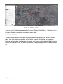
GROUP VIEW
Initially when Map View page is loaded, group mode is shown. In group mode all
the trackers are shown on the map collectively and updated as they move and
their status icons change depending on their current status. Multiple trackers in
Group View can be seen in Figure 9: Group View.
14 | P a g e
Figure 9: Group View
Figure 9: Group View is a standard representation of Google® map. We will
discuss some standard features of the maps here. For detailed learning you may
visit http://maps.google.com
Bar on the left side of the map marked with + and – sign are used for adjusting
up the zoom level. On the top-right side you can see three options available
namely Options, Map, and Satellite.
Type
Description
Map
Only map of the region without any satellite images will be
displayed. If your internet connection is slow speed one, it is
recommended to select this mode as it requires less data to be
transferred to your computer
Satellite
Satellite imagery can be viewed in this mode, with or without
labels
Options
These are custom options provided by Find’n’Secure software
You can zoom in the map towards the tracker by scrolling mouse near the
tracker on your map. You can also hover the mouse pointer over the tracker
icon on the map, to reveal its Information.
TRACKERS CLUSTERS
When all trackers are selected at once, using the Select All button below the
trackers list, clustering of trackers is enabled. When trackers are very close to
15 | P a g e
each other or zoom level of the map is low, then those trackers will form a
cluster, with a number indicating number of trackers in that cluster. As you
zoom in on a cluster the trackers, further away will break free. This will
continue until a specific zoom level (i.e. 17) is reached, where all trackers will
pop out of the cluster.
If you do not wish to zoom one by one and just see the separated trackers
instantly, you can click the cluster, which will automatically zoom in and
ungroup the trackers.
The cluster icon color changes with the number of trackers it contains and
follows the scheme given below:
Number of trackers in cluster
Color
< 10
Blue
> 10 & < 100
Yellow
> 100
Red
If you do not wish to view clusters in group mode, you can select trackers one
by one from the list, instead of selecting all trackers at once.
Also, when in cluster mode, you can remove some trackers by unchecking the
desired trackers from the trackers list.
16 | P a g e
Figure 10: Markers Cluster
MAP INFO-BOX
Tracker icons on the map are clickable and upon clicking them you see various
details of the tracker for quick accessibility and unique geo-coding mechanism.
Figure 11: Map Info-box
As you can see in Figure 11: Map Info-box, it contains all the essential details of
the vehicle as described below:
Property
Description
Unique ID
This ID is assigned by the GUI to identify the
17 | P a g e
tracker on the map. If an Icon Text is specified,
it is displayed instead of GUI generated ID. In
Figure 11: Map Info-box the above clipart it is
0005
Tracker Name
Besides Unique ID is the name of the tracker
Time
Displays the last known reporting time of the
device
Speed
Speed registered at the time of reporting
Latitude
Latitude of the location where location of the
vehicle was registered
Longitude
Longitude of the location where location of the
vehicle was registered
ODO
Current odometer value of the vehicle, if
enabled
GPS
Duration
Status of GPS fix
Possible Values: Valid/Invalid
Duration since which the vehicle is in current
state
Direction and the location of the vehicle.
Location
Currently stopped
Movement Direction
Metric
Convert the metric system used in the window
SNAIL TRACK VIEW
Clicking on any of the trackers present in the trackers list activates snail track
view. Snail Track View is the complete analysis of the particular tracker in realtime. When you click on any of the tracker, the right pane of the browser
window is loaded with the individual mode as shown in Figure 12: Snail Track
View.
18 | P a g e
Figure 12: Snail Track View
In this view, snail plotting is automatically enabled and you can see the track
on which the tracker is moving. If this tracker is installed inside a vehicle and
ignition detection is enabled then you will see the plotting from the place its
ignition was turned ON.
The plotted lines can be switched to Segmented Mode, by checking Segmented
Mode option in the options drop down on right hand side of the map. In
segmented mode, hovering mouse over the lines displays the direction, time,
and speed of the tracker. Tracking lines are color coded and each consecutive
point has alternate shades to easily identify the points of reporting. The line
colors can be changed as described in section Error! Reference source not
ound.. A sample color configuration is given as follows:
Color
Description
Green
0 ~ 80 Kilometers/Hour
Yellow
80 ~ 100 Kilometers/Hour
Red
> 100 Kilometer/Hours
MAP ICONS NOMENCLATURE
Icon
Description
Marks the start point of the journey
Alert sent by the device
19 | P a g e
INFORMATION PANEL
Figure 13: Information Panel
As shown in Figure 13: Information Panel, this panel is divided into four major
sections:
LIVE TRACKING
This panel shows the basic details about the tracker. Following properties of
the vehicle can be viewed in this panel.
Property
Description
Photo
The picture uploaded for this
tracker/vehicle
Tracker Name
Name of the tracker is shown beside
the photo
20 | P a g e
Field of Application & Tracker Model
This property describes the field of
application of the tracker, e.g.
Vehicle Tracking, Personal Tracking,
etc.
Also, the model of this tracker is
displayed next to it.
Information
Information related to this tracker is
displayed here, if available.
e.g. for Vehicle Tracker, license plate
number will be displayed
Driver Information
Displays Name and ID of the driver
associated with the vehicle.
Note: Driver information will be
shown, only if it is enabled
Distance
Distance covered by the tracker from
the starting point
Current Speed
Current speed of the tracker
Average Speed
Average speed for the current trip
Maximum Speed
The maximum speed achieved during
the current trip
Started From
Date, Time, and location of the
starting point of the tracker
Current
Date, Time, and location of the
current position of the tracker
Metric
Change the metric related values in
this panel
Details
Click the button, to display tracker
21 | P a g e
card, used to edit information of this
tracker
Group Mode
Switch from Individual Mode to Group
Mode
SENSORS
This panel displays the sensors enabled for this tracker. e.g. fuel sensor,
temperature sensor, RPM Sensor and battery sensor (personal tracking). The
software supports up to five fuel and temperature sensors, one RPM sensor, and
one battery sensor.
Note: These features are available only in the specific models of the hardware
Figure 14: Sensors
22 | P a g e
ALERTS
This shows all the events and alerts occurring on the device. Left side of the
table shows date and time while right side displays the name of event that
occurred on the tracker.
Figure 15: Alerts
Whenever any event occurs on the tracking unit, it is notified to the user by
the following three methods:
1. Tracker tab in the Tracker Explorer is appended by a red color
rectangle indicating the total number of events occurred
2. Alert window pop’s up
3. Email sent to the group user and as per the settings of the tracker.
HISTORY & CONTROLS
This panel provides convenient options to view the history of your tracking unit
and if your hardware supports output commands then you can control the unit
23 | P a g e
from your desktop or laptop itself e.g., by blocking the engine, locking the
door or blowing the horn to attract public attention in case of theft etc.
Figure 16: History & Controls
HISTORY
Quick combo-box templates allow you to see the history of the tracker quickly
with the options of Today, Yesterday or Custom. Sometimes history of a
particular tracker is quite complicated and understanding it may be a daunting
task. In such cases, we provide a filter which enables you to make the selection
of the time for which you wish to see the history.
24 | P a g e
Figure 17: History
Let us show you an example of a complicated history and a simplified version of
it. Figure 18: History - 24 Hours shows history for a complete day whereas
Figure 19: History - 1 Hour shows the history between 17:00 to 18:00 HRS.
Figure 18: History - 24 Hours
25 | P a g e
Figure 19: History - 1 Hour
Thus you will find that complicated history (Figure 18: History - 24 Hours) can
be easily broken down into segments using time.
HISTORY OPTIONS
The left hand side of this page displays options for the history shown on the
map. You may add any number of trackers that are available, to compare
histories of multiple trackers at any point of time by clicking the ‘Add’ button
below the trackers list. Various options for history configuration are described
as:
26 | P a g e
Figure 20: History Options
27 | P a g e
Property
Description
List of trackers added for viewing history
Trackers List
History is being fetched
History is available and is loaded
1. History is not available and not loaded
Add
Click this button to add more trackers to History
Remove
Select a tracker from the list and click this button to
remove tracker from History
Play selected tracker’s history
Play
Note: Multiple trackers can also be selected by
Crtl/Shift clicking.
To stop map panning while history is playing, use the
Panning option provided in map options on top right.
Stop
Stop playing selected tracker’s history
Route Color
Color used to plot history on map
Animation Speed
Control speed of History playing
Inputs
If you wish to enable coloring of the track for which
specified input was ON you can select the input and
the color
Journey Start
Modify the start date and time of history
Journey End
Modify the end date and time of history
Timeline
Specify the time on which to locate the position of
the tracker. The tracker icon will move to the
nearest position at that time.
Choose the plotting mode
Continuous Shows the complete history for the
period
Plot Mode
Trip Shows trip wise history of the period. Options to
play/pause/stop are available for each trip
Note: Trip wise history depends on the availability of
ignition sensor
Trips Filter
This filter allows you to view either moving trips
only, stopped trips, or both trips simultaneously
Trip Name
Change the name of a selected trip
Details
Show additional details of tracker at this location
28 | P a g e
More Filters
Additional filters for continuous trips, explained in
detail in section More Filters
HISTORY INFO-BOX
Figure 21: History info-box
Clicking on the tracker icon on map pops up the History Info-box, as shown in
Figure 21: History info-box. This windows has the same properties as the infobox shown in Map View (Figure 11: Map Info-box).
POIs can also be added quickly just by double clicking any location on the map.
This is very convenient when you need to mark a historical location as POI.
MORE FILTERS
These filters can be applied to data when the trip is of continuous type.
Figure 22: More Filters
The function of each filter is described below:
29 | P a g e
Filter
Description
Remove Clutter
Removes clutter from the map, caused by incorrect
lines created by invalid data
Break data into trips
Break continuous data into trips
Consider trip, if
distance is greater
than ‘x’ kms
This filter automatically breaks data into trips and
makes sure that a trip is not considered as moving if
the distance travelled is less than the distance
provided
Note: The distance provided should be in kilometres
Consider trip, if
duration is greater
than ‘x’ seconds
This filter automatically breaks data into trips and
makes sure that a trip is not considered as moving if
the duration of travel is less than the duration
provided
Note: The duration provided should be in seconds
DETAILS PANE
30 | P a g e
The details pane displays journey details for the current history.
Figure 23: History Details
To Exit from History module, click the Finish button. You will be redirected
back to Error! Reference source not found..
CONTROLS
Vehicle tracking units may contain functions for controlling the vehicle. Some
standard operations are given as follows:
Force Location Update
Horn Blow
Horn Stop
Lock Doors
Unlock Doors
Block Engine
Unblock Engine
All these operations can be controlled via web-interface if your tracking device
supports them. However, the operations listed above may change with the
model of tracking device.
There are two options to send commands.
31 | P a g e
1. Predefined commands To send predefined commands follow the steps
below:
Select the command you wish to send from the drop down box.
Choose desired channel of transmission, i.e. Network, SMS
Click Send Command
2. Custom commands To send custom commands follow the steps below:
Type in the command1 you wish to send, in the Custom
Command textbox.
Choose desired channel of transmission, i.e. Network, SMS
Click Send Command
Figure 24: Controls
TRACKER DETAILS
The Tracker Details pane consists of all the information related to the use of
tracker. To view this pane, you may either double-click over the tracker in the
Trackers List or by click the Details button in the Live Tracking panel, as shown
in Figure 13: Information Panel.
There are three sections in the Tracker Details pane, as shown in
1. Basic Information
2. Alerts
3. Reminders
Figure 25: Tracker Details
1
If you do not know custom commands for this device, please refer to Device’s User Manual or contact our customer support.
32 | P a g e
BASIC INFORMATION
This section consists of basic information about the tracker. The user can
modify any of these properties2 at their own will.
Figure 26: Basic Information
Property
Description
Tracker ID
Unique ID of the tracker, allotted by
the system
Photo
Upload an image related to the
tracker
Tracker Name
Name of the tracker as seen in the
Trackers List
Description
Description about the tracking device
Tracker ID property cannot be changed. It is automatically generated by the system and is a unique ID to identify the tracker. Also, note that the user
may not be permitted to change any of these properties if specified by the Administrator.
2
33 | P a g e
Field in which this tracker is being
used, you can select from one of the
following:
Field of Application
Vehicle Tracking
Personal Tracking
Asset Tracking
Offender Tracker
Tag Message
If RFID scanner is being used by this
tracker for identification purpose, tag
message will be appended with the
tag ID
Fuel Tank Capacity
Comma separated capacities of up to
five fuel tanks, in liters
Compute fuel while ignition is OFF
Check to compute fuel while ignition
if off
Odometer
Clicking this button displays an
Odometer Tuning window, as
explained in section Odometer Tuning
Others
Optional and for information purpose
ODOMETER TUNING
As you must be aware that the distance computed by GPS, over time is not cent
percent similar to the actual distance covered by the vehicle. So, from time to
time, when a variation is found in odometer values, you can sync the computed
value of the odometer to the actual value, using this module. This module also
displays a date-wise list of values of the odometer. These values cannot be
modified, but can be removed and added for any date.
34 | P a g e
Figure 27: Odometer Tuning
To add new value of odometer, enter the new value, choose metric, date,
time, and click the Add button on the right. If you enter a wrong value, or wish
to remove a previously entered value, select those rows in the list below the
click the Remove button.
ALERTS
You can configure multiple emails and SMS numbers to which the desired alerts
can be sent. You must separate multiple emails and SMS using semicolon (;)
35 | P a g e
Figure 28: Alerts
REMINDERS
You can add various types of reminders to the tracker for performing
maintenance operations on the vehicle. Reminders can be set based on the
following:
1. Distance: Whenever mentioned distance is completed by the tracker an
email is dispatched to the group head. This feature is very useful when
you need to be alerted after vehicle has completed certain distance
like fuel change or tires change. You can choose an appropriate metric
system, using which you wish to enter distance.
2. Date: Notification email is sent on Reminder Date as soon as End Date
is reached.
3. Engine Hours: Whenever a vehicle completes specified Engine Hours
on selected Input, a notification email is sent.
36 | P a g e
Figure 29: Reminders
EVENTS
An events button is displayed on the right hand side of the map. When you click
this button a Recent Events window is displayed. This windows lists all the
events which have occurred on all the trackers, since the time of login. You
can double click on any tracker event in this list, to quickly start Snail Track
View of that tracker.
To clear all previous events listed in this window, you may click the Clear List
button. This will remove all existing events from the list and new events will be
added as they are generated.
To close this window, you may click the Close button.
This window is shown automatically, whenever an event is generated. The
window hides itself after a few seconds. If you require the window not to pop
up every time an alert is generated, you can check the Don’t show alerts
panel automatically checkbox. This will result in the window not being
37 | P a g e
displayed automatically, but only when you click the Events button on right
hand side of the map.
This window is movable and resizable, so you can adjust the size and place it at
a convenient location on your screen if you are monitoring events on a number
of trackers.
Figure 30: Recent Events
FULL SCREEN MAP VIEW
To have a better viewing area on the map, you can hide the Trackers List to
display map on full screen. On right hand side of trackers list, a button to hide
the list is displayed, as shown in Figure 31: Hide Trackers List Button.
Figure 31: Hide Trackers List Button
Click the button to hide the list, and click the button again to bring the list
back to original state.
38 | P a g e
Figure 32: Full Screen Map
QUICK POI
A POI can quickly be added by double clicking on the map at the location where
a POI is required. When you add a POI, a POI details window is displayed, which
contains information about this POI. The latitude, longitude, and description
are automatically filled. You can fill in the remaining required fields and click
on Save button to add this POI. If you change the POI type, the POI icon
changes accordingly. POI color only applies to Default type POIs, and is
displayed as it is changed.
If you want to refine the POI position, you can drag the POI and drop it to the
new appropriate location. As soon as the POI is dropped, the filled in latitude,
longitude, and description are updated.
Once the POI is saved, you cannot edit/modify its information from here. You’ll
need to go to Error! Reference source not found. to modify information
ssociated with this POI.
However, you can remove this POI by clicking on the POI icon and clicking the
Remove button thereafter.
MAP OPTIONS
In top right corner of the map, an Options button is displayed. It consists of a
number of features, which you can enable/disable.
39 | P a g e
Figure 33: Map Options
Option
Description
Arrows
Show/Hide arrows on path plotted in
Snail Track View
POI
Show/Hide POIs
Segmented
Switch from non-segmented plot mode
to segmented mode, as described in
section Snail Track View.
Note: Non-segmented is much faster
that segmented mode and should be
preferred.
Alerts
Show/Hide alert icons from map,
while in Snail Track View
Polygon Geofences
If the selected tracker has a polygon
geofence associated with it, it can be
shown on the map by checking this
option.
Circular Geofences
If the selected tracker has a circular
geofence associated with it, it can be
shown on the map by checking this
40 | P a g e
option.
Routes
If the selected tracker has a path
associated with it, it can be shown on
the map by checking this option.
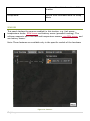
DEBUG LOG
The debug log window is a unique feature of this module. This window displays
detailed information about the current state of the device. The number of
features displayed in this window will vary on the feature availability of the
device. This log will be very helpful while debugging problems when the device
has been installed and is working in the field.
Figure 34: Debug Log
EDIT TRACKER
If you need to edit details of a tracker instantly while debugging, you may use
this feature. Select a tracker you wish to modify, and then click the ‘Edit
Tracker’ button on bottom left. This will open the tracker card in a new
window, where you may edit the tracker details and ‘Save’ all the changed
information.
ADD/REMOVE POI
41 | P a g e
Using this module, you can add/modify/remove multiple Points of Interest
(POIs). These POIs are helpful in identifying a location on map and add that
desired location to the geocoding database.
ADD POI
To add a new POI, navigate to the location of interest using the search tool, on
top right hand corner. Double click on the desired location on the map and a
window titled ‘Edit Place mark’ will pop up, as shown in Figure 35: Edit Place
mark.
Figure 35: Edit Place mark
This window contains the latitude & longitude of the location that was double
clicked on. If you change this latitude and longitude to some other location you
can click on the ‘Fill Address’ button to fetch address for this new location.
Following are the fields in this window:
Field
Latitude
42 | P a g e
Description
Latitude on which POI should be added. By default it is
the location where mouse was double-clicked
Longitude
Longitude on which POI should be added. By default it is
the location where mouse was double-clicked
Radius
Radius of the circular area in which this POI is applicable
Color
Color of the default icon
Type
Icon type to be used on the map
Keywords
Keywords to search POI
Short Name
Name of this location which is shown when mouse is
hovered on its icon
Description
Description for this location
Metric
The metric system used to specify radius
Fill Address
Fetch address from the specified latitude and longitude
Save
Add new location on the map
Remove
Remove this POI from the database. Note that a POI once
removed cannot be undone
Cancel
Cancels the add/modify operation and closes the window
MODIFY POI
To modify an existing POI, locate the POI in the list on left hand side. When
you select the POI, that you wish to modify, you’ll be able to see the POI icon
placed on the map. Click on that icon to display the ‘Edit Place mark’ window
as shown in Figure 35: Edit Place mark. In this window, you can make the
desired changes and click the ‘Save’ button when done, so that all changes are
stored successfully.
43 | P a g e
REMOVE POI
There are multiple methods to remove a POI:
1. Remove single POI by choosing from list
2. Remove single POI using ‘Edit Place mark’ window
3. Remove multiple POI by selecting from list
To remove a POI, select the POI from the list of existing POIs from the list on
the left hand side. Click the ‘Remove’ button to remove the selected POI. You
may also click on the POI icon, of the selected POI, on the map; thereby
displaying the ‘Edit Place mark’ window. In that window you’ll be able to see
the ‘Remove’ button on the bottom left. Click that button to remove the
selected POI. It is also possible to select multiple POIs from the list by pressing
the Ctrl or Shift button on the keyboard and then selecting the desired POIs
using the mouse. After you have selected all POIs that should be removed, click
the ‘Remove’ button below the list. This will remove all the selected POIs.
UPLOAD POI LIST
If you need to add multiple POIs all at once, you can prepare upload the POIs’
list using this feature. To create a POI list, you first need to download the POI
format, using the ‘Download POI Format’ button on the bottom left. There are
detailed instructions in the download package on how to create a POI file for
uploading on the server. Once you have created the POI file, following the
appropriate methods, you are ready to upload that file to the server. Click on
‘Upload POI List’ button in bottom left, which will display a file browser
window. Select the file you wish to upload and click “OK”. This process may
take some time, depending on the number of POIs you are uploading. Wait for
some time until you get a message indicating whether the file was successfully
uploaded or not.
USERS MANAGEMENT
As the name suggests, this option allows you to create/modify/remove the user
accounts from your server and help you in associating various types of tracking
units to the user accounts. We will now help you in setting up one demo
account and associate one tracking unit with it. Click on Users Management
44 | P a g e
Figure 36: Users Management
In Figure 36: Users Management, you can see the list of accounts associated
with the server. There are two types of accounts, as follows:
Fleet Owners: Single or multiple devices can be associated with this
account type
Customer Care: Customer Care executives can be assigned such an
account for controlling all other accounts
Each account has five types of categories viz.:
Active: The user of the account has signed in at least once in the last thirty
days.
Inactive: The user of the account has not signed in in the past thirty days.
Expired: The expiry date associated with the account has passed.
Expiring: The expiry date associated with the account is approaching. The user
of the account will be able to view a message for the same on his/her home
page.
Blacklisted: The accounts which have explicitly been marked as blacklisted.
The user of such an account will not be able to sign into his/her account.
Firstly, Users Management module provides for convenient searching of users
by applying filters on Username, Name, and Company Name. If you need to
arrange users in ascending/descending order by username, name, and company
45 | P a g e
name, you can do so by clicking on the header cell on the top of the list.
Additionally, the accounts can be sorted using type of account, by clicking on
the small blank cell placed above the icons, in the header area.
Secondly, there are various options that can be used on any of the desired
accounts or to create a new account. These are the buttons provided on the
right hand side panel. Each button serves a different purpose, as follows:
Add Account: Create a new account on the server
Modify Account: Modify the details of an existing account
Remove Account: Remove an existing account. Please note that an account
once removed cannot be restored
Blacklist Account: If you need to prevent the user of an account to not be able
to sign in, you can blacklist his/her account. The user will be notified that the
account has been blacklisted, when s/he tries to sign in.
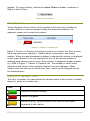
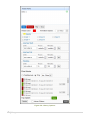
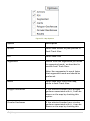
ADD ACCOUNT
The following steps will help you in the creation of a new account and adding a
tracking device to the account:
Click on ‘Add Account’ button
Select Fleet Owners as Account type in the drop-down box
Assign a unique username with which this account will be identified on
the server. In case username already exists on the server the system
will notify that the username already exists. In such a case, you are
required to assign a different username for the account.
Assign a password to access the account. It is recommended that you
choose a strong password i.e., which may not be easily imitated by an
unauthorized person. A strong password usually consist of a
combination of alphabets (both lower and upper case), numerals and
special characters. Dictionary words should be avoided.
Specify an email address. This email ID will be used to send all alerts
that are generated on the software.
Select Account Expiry date (login will be automatically disabled after
this expiry date unless it is extended further). The default value of this
46 | P a g e
field is set to one year ahead of today’s date. Also note that
appropriate e-mails are sent to user, notifying account expiry.
Select the account Creation Date. Default value of this field is today’s
date.
Fill up the remaining details for the new user.
You can also provide additional permissions to the account, as
described on the right hand side features list. While adding multiple
accounts one by one, you might need to apply similar features for
multiple accounts. To ease the selection of feature marking, the
module provides an option to save the selected features in a new
template. To save a template, type in the template name and click the
‘Save Template’ button. You can later select this template from the
template drop down list in the starting of the features list. Selecting a
previously saved template will mark all appropriate permissions
automatically. All features, reports and mapping services can be saved
in a single template. You can create multiple templates for different
permission sets.
*All the fields marked in red color on this form are mandatory and others are optional
Once you are done click on Save
Figure 37: Add Account
ADD TRACKERS TO ACCOUNT
47 | P a g e
After all the details of the account are saved, click the ‘Trackers’ button to
proceed with adding trackers to this account.
This page shows two lists, ‘Available Trackers’ on top and ‘Selected Trackers’
at the bottom. Any tracker can be selected from the list of Available Trackers
and can be added to the list of Selected Trackers to assign them to this user
account. Once you have added the trackers and moved them to Selected
Trackers list, you can now click on the ‘Done’ button to complete the process.
Figure 38: Manage Trackers
Please note that a tracker that is already assigned in to a user account can also
be added to another user account.
REMOVE TRACKERS FROM ACCOUNT
To remove trackers from a user account, go to the Manage trackers page, as
described in the previous section and shown in Figure 38: Manage Trackers.
Select the trackers you wish to remove from the Selected Trackers list and
click on ‘Remove’ button on bottom left. When you remove a tracker, it’ll
automatically be added to the list of Available Trackers. Click the ‘Done’
button to save all changes and exit.
MODIFY ACCOUNT
Modify Account is similar to Add Account in the functionality. Some unique
fields associated with the account and the trackers are not editable in the
modify section.
48 | P a g e
Shortcut: To modify any account simply double click on the account name in
the Users Management
REMOVE ACCOUNT
This option removes the selected account and all details associated with this
user.
Caution! Removing account from the server will destroy all the data present
in the database and this is an irreversible process.
BLACKLIST ACCOUNT
You can select single or multiple accounts to blacklist due to any reason
whatsoever. Upon blacklisting an account it doesn’t allow the user to login to
the software but it still keeps on storing all the data being received from the
tracking devices.
REMOVE FROM BLACKLIST
This option removes the account from the blacklist and now user will be able to
have complete access to his account.
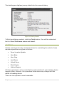
DATABASE MANAGEMENT
Administrators should make use of the database management system to
perform operations on the software databases. We strongly discourage you
from directly performing any operations on the database of the software as
even the slightest error may render the whole system useless. When you click
on the Database Management option, you’ll be presented with a page similar to
Figure 39: Database Management.
49 | P a g e
Figure 39: Database Management
Here you can see a list of trackers with their IMEI, SIM No., and Keywords. You
might opt to either select Complete Database or Select Trackers manually.
REMOVE RECORDS
You can select the period between which you wish to remove data from the
trackers’ database. Click on Remove Records to perform the operation.
Caution!
It is always wise to take the backup of the database before performing any
operations on the database. In the next section we’ll show how to take
backup of entire database.
COMPLETE BACKUP
This option allows you to perform backup of the entire database. You can
download and store the backup depending upon your choice by selecting
options above this button.
Download complete database backup as an archive
Store copy of the backup on the server itself
50 | P a g e
It is always advisable to download the file on your personal computer and move
the file to any archiving facility like DVD, pen drive etc. Storing backup file
over the server can be useful in the eventuality of your system developing
some kind of a database corruption which needs to be restored immediately
from the stored backup file. Backup filenames are generated automatically
using random digits and a log is maintained on the server. The format of the
backup file is gzip compressed file which can be uncompressed by using gunzip
command available on Linux systems.
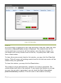
FUEL SENSOR
A wide variety of fuel sensors are available in the market, each of which has a
different configuration. These configurations should be set up in the software
so that they are calibrated properly.
On clicking this option you will see all the existing profiles in the left pane.
To create a new fuel profile, click the ‘New’ button, fill up the fuel
profile card and click the ‘Save’ button.
If you wish to modify an existing profile; select the profile, edit fuel
profile card values and click the ‘Save’ button to commit changes.
To remove an existing profile, select the profile you wish to delete and
click the ‘Remove’ button. This will remove the fuel profile
permanently.
The Fuel Profile card contains the following parameters:
Parameter
Description
Profile Name
Name of this profile
Enable auto compute
Check this option, if the fuel profile
should be automatically computed by
the software
Reference Voltage
Measured voltage when the fuel tank
is full
Empty Tank Voltage
Measured voltage when the fuel tank
is empty
Additional Parameters
Additional properties of the sensor
provided by the vendor
51 | P a g e
TEMPERATURE SENSOR
A wide variety of temperature sensors are available in the market, each of
which has a different configuration. These configurations should be set up in
the software so that they are calibrated properly.
On clicking this option you will see all the existing profiles in the left pane.
To create a new temperature profile, click the ‘New’ button, fill up
the temperature profile card and click the ‘Save’ button.
If you wish to modify an existing profile; select the profile, edit
temperature profile card values and click the ‘Save’ button to commit
changes.
To remove an existing profile, select the profile you wish to delete and
click the ‘Remove’ button. This will remove the temperature profile
permanently.
The temperature profile card contains the following parameters:
Parameter
Description
Profile Name
Name of this profile
Enable auto compute
Check this option, if the temperature
profile should be automatically
computed by the software
Temperature Lower Limit
Lowest range of temperature in
Centigrade which can be identified by
this sensor
Temperature Upper Limit
Highest range of temperature in
Centigrade which can be identified by
this sensor
Beta Constant
Beta Constant value of the thermistor
Thermistor Resistance
Fixed resistance value of this sensor
Reference Voltage
Voltage on which this sensor will
operate
Fixed Resistance
Value of the fixed resistance
Additional Parameters
Additional properties of the sensor
provided by the vendor
GLOBAL SETTINGS
52 | P a g e
Please refer to Chapter 3 – Installation for options related to System Settings.
MODIFY PASSWORD
You can use this option to modify the password of administrator account. It is
important to keep a strong password for your administrator account as the
complete functioning of the software may be hampered if this is leaked out.
This module also indicates the strength of your password so that you can
choose a good and strong password.
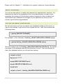
RESTORE DATABASE FROM BACKUP
We will now show you how to restore your database backup on the server in
case of any mishap. Login to the Linux system as root, start the terminal the
following steps:
> gunzip [BACKUP FILENAME]
For example, if the filename is backup_4dbd652e82e8b59ee38fbf8a.sql.gz
> gunzip backup_4dbd652e82e8b59ee38fbf8a.sql.gz
This will produce the file backup_4dbd652e82e8b59ee38fbf8a.sql. By default
the name of the database used by the software is fnsv4. You are required to
clear this database before you can perform restore.
>mysql –p fnsv2
Password: *******
mysql>DROP DATABASE fnsv4;
mysql>CREATE DATABASE fnsv4;
mysql>exit
>mysql –p fnsv4 < backup_4dbd652e82e8b59ee38fbf8a.sql
53 | P a g e
CHAPTER 2
ADVANCED TOOLS FOR ADMINISTRATORS
In the previous Chapter we visited options available to administrators via
software interface to perform administrative operations but sometimes it
becomes important for administrators to make use of Linux tools for debugging
software issues. We will go through the series of such tools in this Chapter
starting with MySQL administrator Utility.
MYSQL ADMINISTRATOR UTILITY
You can download and install MySQL administrator utility from the MySQL
website, http://www.mysql.com and moving to the section Downloads > GUI
Tools. Once you complete download and installation, you are required to
perform following operations on the Linux server:
Login as root user in the Linux system
Run Terminal
Execute mysql –p fnsv4
Enter your MySQL root user password
Execute mysql> GRANT ALL ON *.* TO ‘user’@’192.168.1.10’
IDENTIFIED BY ‘password’
This command will allow user with username as ‘user’ to login from
host IP address 192.168.1.10 and the password provided is ‘password’.
You can modify this command as per your requirements. For more
understanding please refer to MySQL manual.
Please be aware of the firewall system on your network before
making the connection to MySQL. Port number 3306 is default port
for communication with MySQL and therefore your firewall should
allow communication on this port.
Once you have performed the above steps your MySQL is ready to connect via
any PC using MySQL administrator. Open the MySQL administrator utility on
your computer and fill up the following fields:
Server Host : IP address or hostname of the server on which MySQL is
running
Username : user
Password : password
Click on ‘OK’
Your MySQL administrator will be connected to the MySQL database engine. You
can go through the wide range of documentation available for this utility to
become friendly with this utility. Some of the tasks that you can do using this
utility are:
Backup — You can schedule backup projects
Restore
Database maintenance
Server health monitoring
Server logs
Replication Status
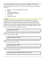
TCPDUMP
The most common source of problems with tracking devices is incorrect
configuration of these tracking devices for communication over GPRS. This
utility can help you identify if the tracking devices are communicating well
with the server or not. Find’n’Secure® software opens up port number 21000 by
default for communication over UDP and TCP/IP. Given below are some of the
useful commands and their respective meanings.
>tcpdump port 21000
Capture all the packets coming in and going out of the server related to UDP
and TCP/IP port number 21000
>tcpdump udp port 21000
Capture all the packets coming in and going out of the server related to only
TCP Protocol port number 21000
>tcpdump tcp port 21000
Capture all the packets coming in and going out of the server related to only
TCP/IP Protocol port number 21000
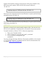
>tcpdump udp port 21000 and host 192.168.1.10
55 | P a g e
Capture all the packets coming in and going out of the server related to only
UDP Protocol port number 21000 with the host having IP address of
192.168.1.10
>tcpdump udp port 21000 and dst host 192.168.1.10
Same as previous command with the only difference to capture packets having
destination host as 192.168.1.10
>tcpdump udp port 21000 and src host 192.168.1.10
Same as previous command with the only difference to capture packets having
source host as 192.168.1.10
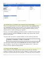
WIRESHARK
Wireshark is a kernel level network packet capture utility. You can see it as a
GUI tool with capabilities of tcpdump utility, discussed in the previous section.
To install wireshark on Ubuntu 12.04.2, follow the steps below:
1. Open a new Terminal window
2. Install wireshark by typing apt-get install –y wireshark
3. To run wireshark in background type:
wireshark &
You can go through the huge collection of documents available on the internet
for learning basic features of wireshark and also find the documentation from
its website http://www.wireshark.org
56 | P a g e
Figure 40: Wireshark
CAPTURING WITH TCPDUMP FOR VIEWING WITH WIRESHARK
There are occasions when you want to capture packets using tcpdump rather
than wireshark, especially when you want to do a remote capture and do not
want the network load associated with running Wireshark remotely (not to
mention all the X traffic polluting your capture).
However, the default tcpdump parameters result in a capture file where each
packet is truncated, because tcpdump, by default, only captures the first 68
bytes of each packet.
To ensure that you capture complete packets, use the following command:
tcpdump -i <interface> -s 1500 -w <some-file>
You will have to specify the correct interface and the name of a file to save
into. In addition, you will have to terminate the capture with ^C when you
believe you have captured enough packets.
SETTING UP MYSQL MIR ROR
Server failures are unavoidable and can make you lose all your vital data
related to tracking of the units and in such a scenario it is most crucial to make
the service up and running as soon as possible. To keep your service running all
57 | P a g e
the time with 99.99% uptime you need to setup the infrastructure that allows
you to have redundancy in the data so that in the eventuality of your primary
server going down you can switch to your secondary server. MySQL has an inbuilt ability to replicate the data on one or more storage servers. In this
section we will show you how to create a mirror for your MySQL service. You
need one additional server installed with the same version of the MySQL to
avoid any problems, let us denote your primary server with name “MAIN” and
your secondary server with name “MIRROR”
SETTINGS FOR MAIN
1. Create User in MySQL
mysql> mysql –p
Enter your password
mysql> GRANT REPLICATION SLAVE ON *.* TO
‘repl’@’%.mydomain.com’ IDENTIFIED BY ‘password’;
2. Open my.cnf, navigate to section [mysqld] and add the following lines :
log-bin = mysql-bin
server-id = 12345
3. Issue the following commands in MySQL :
mysql> FLUSH TABLE WITH READ LOCK;
mysql> SHOW MASTER STATUS;
Record down ‘File’ and ‘Position’ and quit mysql
4. On the Linux shell prompt issue the following command :
#>mysqldump –all-databases –master-data #>dbback.sql
58 | P a g e
5. Re-enter MySQL and issue following commands :
mysql> UNLOCK TABLES;
Once you have completed the above steps your primary server is ready to allow
secondary server for fetching data.
STEPS FOR MIRROR
1. Copy dbback.sql file created over the MAIN server and move it to
MIRROR server. Thereafter, issue the following command to create a
copy of the database on the MIRROR server:
#>mysql –p < dbback.sql
2. Open my.cnf, navigate to section [mysqld] and add the following lines :
server-id = 67890 //this ID should not match master
3. Issue the following command in MySQL prompt:
mysql> CHANGE MASTER TO
MASTER_HOST = ‘MASTER HOSTNAME OR IP ADDRESS’
MASTER_USER = ‘USERNAME’ //repl as created above
MASTER_PASSWORD = ‘PASSWORD’ //password as created above
MASTER_LOG_FILE = ‘LOG FILENAME’ //as you recorded above
MASTER_LOG_POS = ‘LOG POSITION’; //as you recorded above
mysql> START SALVE;
All the steps required for slave setup are now complete and data replication
should start as per the requirement. In case you face any sort of issue, you may
checkout the log files situated at the locations /var/lib/mysql.
59 | P a g e