1
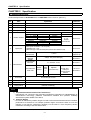
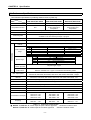
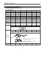
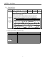
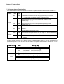
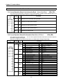
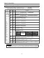
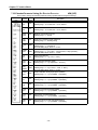
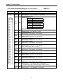
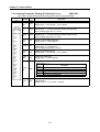
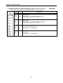
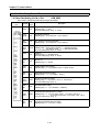
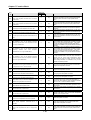
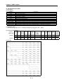
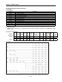
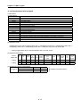
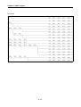
Appendix 1 Positioning Terminology
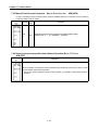
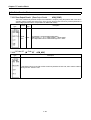
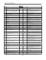
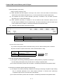
operation
is
downward.
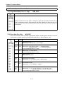
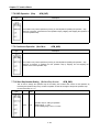
External
regenerative
resistor consumes the regenerative energy as
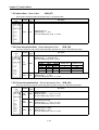
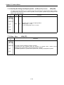
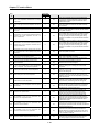
Flash memory
resistance and obtains the regenerative brake
This is used to save the parameter and positioning
torque and enables the overall acceptability of
data for the backup memory without battery. As
regenerative system during stop. Also it is used for
there is no battery, it is not necessary to maintain
the frequent acceleration/deceleration.
the battery.
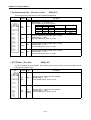
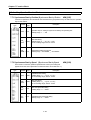
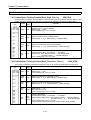
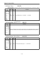
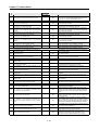
High speed homing
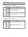
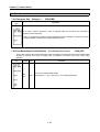
External input high limit (Forward limit switch
When high speed homing, the axis does not detect
signal)
the near point dog and returns to the mechanical
This is the input signal to inform the user that the
origin. This is effective only in the status that the
high limit switch (b contact configuration, always
positioning such as floating point or homing is
ON) is activated out of the action range where the
completed.
positioning control is carried out. The positioning
action stops when external normal direction limit
switch signal (b contact) is OFF.
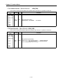
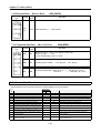
Feed pulse
This is the output pulse from positioning module to
Servo driver or stepping driver. It is also called as
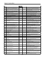
G code
command pulse.
This is the standardized (coded) 2 digit value
(00~99) that indicates various control function of
Feed screw
numeric control module. It is also called “G function”.
This is the basic screw mechanically in the
Ex;
positioning by screw rotation. Ball crew is often
G01 Linear interpolation
used to reduce backlash and numeric error.
G02 Circular interpolation CW
G04 Dwell
Feedback pulse
G28 Homing
In order to check if the machine acts reliably
G50 Max. Spindle speed setting
according to command pulse generated from
positioning module, if command pulse is generated
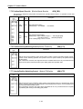
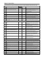
Gain
against 10,000 pulse, the feedback pulse of 10,000
The change of ratio between two values that have a
pulse returns from Servo encoder. After then, the
proportional relation. In case of Graph, it is the
residual deviation value (droop pulse) becomes “0”
change of tilting of characteristic curve. For
and it is judged that it complied with command
example, when 10 is output for the 10 input, output
pulse very well.
will be changed as 12.5 by changing the gain.
Refer to “deviation counter”terminology.
GD
2
Fixed-feed
Inertial moment. Total sum of each small area
This is the feeding of the fixed dimension to cut 제
dimension composing of the material that multiplies
지 and bar work piece by the goal dimension. The
by the square of each distance (r ) of each area
increasing system positioning is often used.
from the given straight line.
Appendix 1-5