1
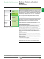
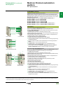
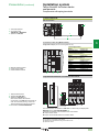
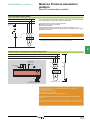
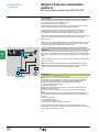
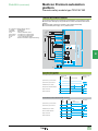
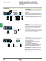
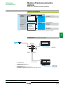
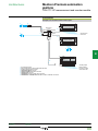
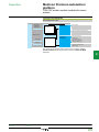
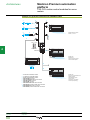
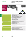
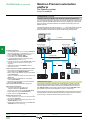
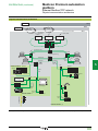
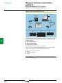
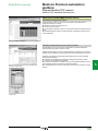
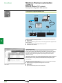
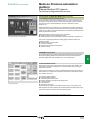
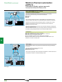
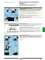
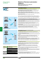
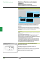
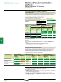
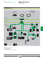
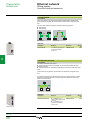
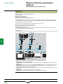
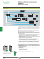
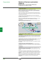
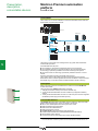
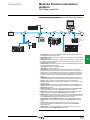
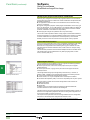
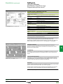
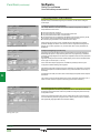
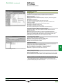
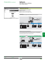
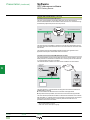
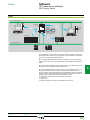
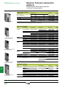
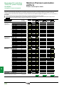
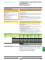
Functions (continued)
Modicon Premium automation
platform
Hot Standby system
Unity Pro software
Functions (continued)
Management of supervision transparency (SCADA)
Transparency of communication with level 2 (supervisor, third-party device, etc.)
when the Primary PLC is switched to the Standby PLC by another pair of Ethernet
Modbus/TCP TSX ETY 4103/5103 modules. Therefore, communication with a
redundant architecture is similar to that with a standard architecture. This
transparency is the result of the automatic “IP” and “IP + 1” address assignment
mechanism.
This transparency also applies with Modbus when using the TSX SCP 114 PCMCIA
card (Modbus slave protocol in RS 485) inserted in the TSX SCY 21601 communication
module (automatic “n” and “n + 1” address assignment mechanism).
1
2
Memory space
All the memory space reserved for the application program and the data is managed
by the Hot Standby system with Unity Pro software. With an embedded 192 KB or
440 KB RAM memory (depending on the model), the RAM memory for the
TSX H57 24M and TSX H57 44M processors, dedicated to Hot Standby
applications, can be increased for the application program to 768 KB or 2048 KB
(depending on the model) by the addition of a PCMCIA memory card.
3
Configuration
Inputs
Inputs
1
Hot Standby
Hot Standby
The installation of the application program does not differ
fundamentally from installing a program for a single PLC.
It essentially uses the information requested by dedicated
dialogue boxes, filled in during configuration in Unity Pro.
4
Cyclic transfer of the application context
Application
program
Data
(coprocessor)
2
Data
(coprocessor)
Application
program
(1st section only)
CPU Sync link
Outputs
Outputs
At the start of each scan cycle, the content of the Primary
PLC data memory is transferred to the Standby PLC via
the dedicated CPU Sync link, at the same time as the
contents of the I/O status tables are transferred to it. The
Hot Standby system is thus able to transfer, from the
Primary PLC to the Standby PLC, a data area (I/O image,
located internal data (1) and unlocated internal data) of:
v 192 KB max. with the TSX H57 24M processor
v 440 KB max. with the TSX H57 44M processor
The principle of the exchanges, as well as exchange times
according to the volume of data, are described in the
diagram opposite with:
1 Hot Standby system: 10 ms per 100 KB
2 Data transfer by the coprocessor: 30 ms per 100 KB.
This data transfer runs in parallel with execution of the
Primary PLC application program
Standby PLC
Primary PLC
5
6
7
8
(1) The first 100 %MW words in each located data area are not exchanged. They can therefore
be assigned to data for processing specific to each Primary or Standby PLC.
9
10
Presentation:
page 4/52
Description:
page 4/53
Architectures:
pages 4/54 ...
References:
pages 4/60 ...
4/59