1
1. If the horn option is selected then this relay can be used to drive an external horn
or bell. Whenever either a high or low alarm condition starts the relay is activated
(closed). If the alarm condition is cleared then the relay is also cleared. If the reset button
is pushed or the external reset/mute input is activated then the horn relay is
cleared. If the horn is muted then it will not reactivate until the alarm condition is
cleared and another starts.
2. If the common alarm option is selected then this relay will be activated when any of
the following conditions exist:
• High alarm
• Low alarm
• Pump Temperature Failure
• Pump disabled by fail to start test
This common alarm condition can be used to drive an alarm light, telephone dialer, or
telemetry system.
OPTION SWITCHES
There are six switches on the back of the controller which select several different
options.
SW1 / When this switch is set the fail to start test is enabled
SW2 / When this switch is set the temperature fail condition is latched up until reset
SW3 / When this switch is set the seal fail input is inverted (open is fault)
SW4 / When this switch is set the aux relay is the common alarm. If it is not set then the aux relay is
the horn output.
SW5 / When this switch is set the low and high alarm relays will cycle to cause a lamp blink
SW6 / When this switch is set the time between pump starts and the delay for the fail to start test is
12 seconds instead of 6 seconds
FAULT OUTPUTS
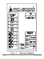
There are seven fault lamps with corresponding driver outputs. They are use to display
the following fault conditions:
1. Floats out of sequence
2. Pump 1 seal fail
3. Pump 2 seal fail
4. Pump 1 temperature fail
5. Pump 2 temperature fail
6. Pump 1 disabled
7. Pump 2 disabled
Each of these has a corresponding relay drive output. These outputs are designed to
drive the coil of a 12VDC relay external to the controller. A source of 12VDC is also
provided. To use these outputs one side of the relay coil is connected to 12VDC and the
other coil connection is connected to the driver output.
3.0 SPECIFICATIONS
3.1 Float and Sensor Input
There are five float inputs, two seal fail sensor inputs, two temperature fail inputs, and
two disable inputs. They use current limiting resistors, filter capacitors and zener
diodes for transient protection. They also have both a hardware and a software filter
on these inputs to improve immunity from noise. They have the following specifications:
PRIMEX™
4
PC-2000 Specifications