1
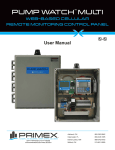
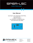
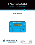
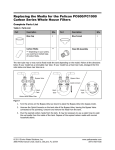
PC-1000
DUPLEX PUMP CONTROLLER
User Manual
WWW.PRIMEXCONTROLS.COM
Ashland, OH
800-363-5842
Clearwater, FL
800-349-1905
Detroit Lakes, MN
888-342-5753
Milford, OH
513-831-9959
PN 1038549A
© 2013 SJE-Rhombus® Rev 09/13
PRIMEX is a trademark of SJE-Rhombus®
PC1000
1.0 INTRODUCTION
The model PC-1000 is a float switch based duplex pump controller intended primarily for wastewater
lift station and other pump down applications. It includes sensor inputs for the seal fail and temperature fail sensors for most submersible pumps. It connects to four switches to measure the tank level
and has out puts to control two pumps, an alarm horn, a seal fail light, and a high alarm light. It has
built in HOA [hand-off-auto] switches, and pump running lights. A lead pump selector switch permits
either pump to be selected as lead pump or alternation can be selected causing the pumps to alternate as lead. The PC-1000 uses removable terminal strips to make replacement in the field quick
and easy. With the addition of an enclosure, circuit breakers, and motor starters, the PC-1000 makes
a complete low cost lift station controller.
2.0 OPERATION
The PC-1000 uses four normally open floats as level sensing inputs so when the tank is empty all
of the floats are open. On rising water the Off float closes first which causes the controller to take
no action. The Lead float will close next as the water rises. The controller will then turn on the lead
pump. If this pump causes the water level to fall, the lead pump will be turned off when both the Lead
and Off float are out of the water and open. If the lead pump is not sufficient to control the water level
then the lag pump will be started when the Lag float closes. The two pumps will not be turned off until
the Lag, Lead, and Off floats are out of the water and open, at which time, all pumps will be turned off.
The controller has delays built into the software, which will insure that whenever a pump is turned on,
the second pump cannot come on for at least 8 seconds. Another delay insures that when a pump is
turned off the other one cannot turn off for 4 seconds. These delays help insure smooth pump operation and prevent excessive electrical surges.
The last float input is for the High float. Whenever the high float is under water [closed] then the high
alarm condition is set. When a high alarm condition is set the alarm light will flash on and off, and the
horn will be activated. The horn can be silenced using an external mute button connected to pin j2-9.
Both the alarm light and horn will turn off when the high float input opens. The PC-1000 has an alarm
test button on the front panel which can be used to test the alarm horn and light.
The pump controller has two inputs for pump seal fail [leak] sensors [one for each pump]. These
inputs measure the resistance between the input and ground. If the resistance is less than 50,000
ohms then the seal fail indicator for that pump will be turned on. This action does not disable the
pump, however, it does demote the pump to the lag position in the alternation order.
The pump controller has two inputs for pump temperature sensors. If the controllers detects a short
between these inputs and ground then a temperature failure condition does not exist. If the short to
ground is removed then a temperature failure condition exists and the pump associated with that input will be disabled and the Temp Fail indicator illuminated. This condition does not latch up and will
return to normal if the short to ground is reestablished.
All of the float and sensor inputs are transient protected and filtered to prevent electrical interference
from causing improper operation.
PRIMEX™
2
PC-1000 Specifications
The controller has two switches that select what mode the two pumps are in. These HOA switches
have the following function:
H
O
A
When in HAND the pump will be constantly called to run.
When in OFF the pump will be off.
When in AUTOMATIC the pumps will be called by the pump controller.
The Hand and Off functions of these switches will operate even if the controller is off or has failed.
The controller has a switch that is used to select the lead pump. When this switch is in the center
position [ON] then the two pumps will alternate as lead pump each pump cycle. When in the 1-2 position then pump one is the lead and when in the 2-1 position pump two is the lead.
The controller has two inputs, which should be connected to the auxiliary switches on the two motor
starters. These inputs, when shorted, cause the pump running indicators to be illuminated. Using
these inputs may eliminate the need for panel-mounted pump running lamps.
3.0 SPECIFICATIONS
3.1 Float and Sensor Input
There are four float inputs, two leak sensor inputs, and two temperature fail inputs. They use current
limiting resistors and a zener diode for transient protection. They also have a resistor/capacitor filter
as well as a software filter to avoid electrical interference. They have the following specifications:
Short circuit current
Open circuit voltage
-
less than 2 mA.
5.0 VDC
3.2 Aux contact inputs
There are two sets of inputs for the auxiliary contacts on the motor starters. When these inputs are
shorted, the pump running lamps are illuminated. These inputs have the following specifications:
Short circuit current
Open circuit voltage
-
less than 2 mA.
12.0 VDC
3.3 Relay outputs
There are three form A [SPST] relay outputs. Two are to call the pumps and one for the seal fail.
They have the following specifications:
Maximum current at 120 VAC
Maximum voltage
-
5Amps with a resistive load
140 Volts
3.4 Driver outputs
There are two 12VDC driver outputs. They are used to drive the alarm light and alarm horn which
must be 12VDC devices or 12VDC relays. They can drive a maximum of 100 mA.
PRIMEX™
3
PC-1000 Specifications
3.5 Power inputs
The controller is designed to run on 120 VAC control power. It is internally fused and protected with
a MOV transient protector. It uses a transformer isolated regulated power system with the following
specifications.
Input voltage 120 Volt A.C. + or - 15%, 50 to 70 Hz
Maximum current 0.25 Amps
4.0 CONNECTOR PIN DEFINITIONS
CONNECTOR J1
PIN FUNCTION
1
OFF FLOAT INPUT
2
GROUND
3
LEAD FLOAT INPUT
4
GROUND
5
LAG FLOAT INPUT
6
GROUND
7
HIGH ALARM FLOAT INPUT
8
GROUND
9
PUMP 1 SEAL FAIL SENSOR INPUT
10
GROUND
11
PUMP 2 SEAL FAIL SENSOR INPUT
12
GROUND
13
PUMP 1 TEMPERATURE FAIL SENSOR INPUT
14
GROUND
15
PUMP 2 TEMPERATURE FAIL SENSOR INPUT
16
GROUND
CONNECTOR J2
PIN FUNCTION
1
120 VAC HOT POWER TO CONTROLLER
2
120 VAC NEUTRAL POWER TO CONTROLLER
3
CHASSIS GROUND
4
HIGH ALARM LIGHT NEGATIVE [-] CONTACT
5
HIGH ALARM LIGHT POSITIVE [+] CONTACT
6
SEAL FAIL RELAY CONTACT
7
SEAL FAIL RELAY CONTACT
8
RUN INPUT 2, CONNECT TO AUX CONTACT STARTER 1
9
MUTE SWITCH INPUT
10
ALARM HORN NEGATIVE [-] CONTACT
11
ALARM HORN POSITIVE [+] CONTACT
12
GROUND
13
RUN INPUT 1, CONNECT TO AUX CONTACT STARTER 1
14
POWER TO MOTOR STARTER 2
15
POWER TO MOTOR STARTER 1
16
120 VAC HOT MOTOR STARTER POWER
Notes: Header and plugs use copper conductors only.
Torque requirement for plugs 1.47 Ft. Lbs.
Unit operates at “Pollution Degree 2”.
PRIMEX™
4
PC-1000 Specifications
FIG. 1
Pc-1000
DUPLEX PUMP CONTROLLER
PRIMEX™
5
PC-1000 Specifications
FIG. 2
PRIMEX™
6
PC-1000 Specifications