1
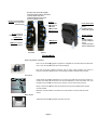
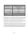
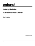
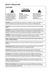
Coaxial HD Video Streamer
HD Video Streamer Model:
Mode GI-TVLHD-1002
Package Contents
1.
2.
3.
4.
5.
6.
7.
8.
HD Video Streamer :Transmitter Unit
HD Video Streamer: Receiver Unit
Wall Plug Mains Power Adaptors (x2)
IR Transmitter (Blaster)
IR Receiver (Eye)
Vertical Mount Stands(x2)
Wall Mount Brackets (x2)
Quick Set Up Guide.
DC input: Only connect the supplied
wall mount power supplies. Connection
of wrong supplies may cause
permanent damage to the unit or
prevent it working correctly
IR input: Connect IR Blaster
and position in view of the
source IR sensor
IR input:
input
Connect IR Eye
and position in
view of the
remote control.
RF Coaxial Input:
Input
Connect to TV
RF link: Connect to
Home Coaxial Network
HDMI Output:
Connect to main TV
HDMI Output :
Connect to
remote TV
HDMI input: Connect
to STB HDMI output
Transmitter
Power Indicator LED
Green: Normal
Amber:
Flashing IR activity
Steady: USB upgrade
Wireless Indicator
LED
Blue:
Flashing: trying to
connect /waiting for
source
Steady: Connected
Steady : USB upgrade
Receiver
Accessories
Wall Plug Power Supplies
Two 5.5V 2.0 A wall plug power supplies are supplied for the transmitter and Receiver
units. They are identical and can be interchanged.
Only use the power supplies provided. Use of other power supplies may result in
incorrect operation or permanent unit damage and will invalidate any warranty.
IR Control
Using the IR accessories supplied you can control your HD source from the remote TV.
Connect the IR Eye to the receiver unit and the IR Blaster to the Transmitter unit. Use
the HD source handset to control your content as if you were at the main TV.
IR Eye: Connect to Receiver Unit and position the Eye to be visible by the remote
control handset
IR Blaster: Connect to the Transmitter unit and position in front of HD source IR
Sensor
Base Stand
The Aluminium Stands provided orientate the units.
Page 2
Installation and Connection Diagram
Page 3
1.
Remove all parts from packaging and identify each part:
2.
On the Transmitter Unit: Connect a good quality HDMI cable from source HDMI
output to the transmitter HDMI (input) connector. If you are going to view the
content on a main TV connect another good quality HDMI cable between the
transmitter HDMI output (TV) connector and the TV HDMI input. Connect the IR
Blaster into the IR socket and position the blaster in front of the IR sensor on the
set-top box, (refer to its handbook for position of sensor). A set-top box source will
have an RF output (RF2) which should be connected to the coaxial RF input of the
HDMI transmitter. The home network coaxial cable should be connected to the LINK
output of the Transmitter unit. Switch on the power to the main TV and turn on the
set-top box. Connect the power adaptor jack plug into the DC input of the HDMI
transmitter unit and mains plug in to the wall socket. Switch the mains power on
and the unit will begin its installation.
3.
On the Receiver Unit connect the HDMI output to the remote TV HDMI input using a
good quality HDMI cable. Connect the IR eye to the IR socket and position the IR eye
such that it can be seen by the remote control handset. Connect the RF output of
the HDMI transmitter to the RF (aerial) input of the TV. Switch on the power to the
TV. Connect the power adaptor jack plug into the DC input of the receiver unit and
the mains plug in to the wall socket. Switch the power on and the unit will begin its
installation.
4.
The units will automatically configure and connect. During installation the TV will
display a start-up screen and the Blue LED will flash indicating the wireless is
connecting. Once connected the Blue LED will stop flashing and the units will be able
to stream video when sent from the HD source.
Page 4
Technical Specification
Dimensions mm (inches)
Supported HD Resolutions
Supported Audio Formats
Compression
: Video
: Audio
Content Security
HDMI Connectors :Transmitter
: Receiver
Range
IR Control
Power Adaptor
Operating Temperature Range
136mm x 145mm x 34mm (5.3”x 5.7” x 1.3”)
1080p60/50/24, 1080i60/50, 720p60/50,
576p50, 480p60, 480i60.
Stereo PCM
H.264/MPEG4-AVC High profile
MPEG2
Paired receivers with WPA2 AES
HDCP
Single input, single output (loop through)
Single output
>150 Meters depending on Coaxial cable loss
IR Eye on Receiver: IR Blaster on Transmitter
AC Input: 90V -264V 50/60 Hz DC Output 5.5V 2A.
+5°C - +40°C, indoor use only
Both the transmitter and receiver units come pre-loaded with all operational software
required; the user simply connects the units and powers the units using the supplied
wall plug adaptors. The transmitter and receiver then automatically go through a
configuration routine. When completed the units are ready to stream HD video.
Software updates and functional upgrades will be made available in the future to
enhance the performance of the units. These software upgrades will be available to
download from the company website and should be stored onto a USB stick.
Software upgrades are performed by connecting the USB stick in turn to both
transmitter and receiver units. With the USB stick connected to the USB port the power
is cycled and the upgrade is automatically loaded. If required units can be returned to
the factory default settings by holding down the reset switch and power cycling the unit.
This will return the unit to the original software version as supplied from the factory at
manufacture and should not be done unless instructed by the product support team.
Page 5
Troubleshooting guide
General note: Check all connections between transmitter and receiver units with
the source and TV are correct and not damaged. Please refer to the set up
configuration instructions if unsure.
I do not see a picture on the remote TV
•
•
•
•
•
•
Check that the TV is switched on
Check the TV is set to display from the HDMI port.
Check that the Receiver Green and Blue LED are on (not flashing).
No LED: check the power supply is connected and switched on at
the wall plug.
Blue LED is flashing fast: Receiver is not connected.
•
Check Transmitter
•
Check the coax connection from transmitter to
receiver.
Blue LED is flashing slowly: Connected but waiting for Source
input
•
Check Source is switched on
•
Check HDMI cable between Source and TX input
connector.
Restart the Receiver (power cycle)
Check the HDMI cable between the Receiver unit and TV is connected and
not damaged.
Replace HDMI cable
Check the picture quality through the coaxial RF output port directly to the
TV RF input
The picture quality on the remote TV is poor
•
•
•
Check the coax connection from transmitter to receiver.
Reposition the Receiver unit: Signal strength maybe too low or on the
edge of range.
Check the picture quality on the main TV (Transmitter Loop through). If
this is poor then the quality of the input signal is inadequate.
Page 6
I get an HDCP warning on the HDTV but no video
•
No sound on the remote TV
•
•
•
•
Some sources have Content Protection & Authentication issues; please
check with the manufacturers for software upgrades.
Disconnecting then reconnecting the HDMI connectors can
sometimes solve the problem.
Check the volume setting on the TV.
Check the volume setting on the source.
Check the HDMI cable is not damaged, unplug and inspect, reconnect.
Restart the Receiver (power cycle).
I cannot control my source device from the remote location
•
•
•
Check the IR Eye is not damaged and is connected correctly to
Receiver unit
Ensure the IR Eye is positioned correctly to be seen by
remote control
Check the condition of the batteries in the remote control
Check the IR blaster is not damaged and connected correctly to
Transmitter unit.
Ensure the IR Blaster is positioned correctly to be seen by
source IR sensor.
the
the
the
the
Ensure any inline amplifiers have a HDMI bypass kit fitted to allow
correct control of the IR sensor.
Page 7
Frequently Asked Questions
•
Are all makes of HDTV supported?
The HDMI standards imply that complete interoperability should be possible but
some products may implement these rules slightly differently to others leading to
complications with some combinations. See the specification page for the list of
resolutions and frame rates supported. Some monitors may have a HDMI connector
but not support HDCP and will lead to authentication errors.
•
Are all source devices supported?
In general most HDMI sources should be supported.
•
Are all IR remote controls supported?
The unit operates an IR pass through and requires no advance knowledge of the
codes used and hence supports all 34-38 kHz remote controls.
•
How do I set up the units?
The setup of the units is a simple procedure described in the set up guide.
•
What is the range of the units?
The range of the units in low loss cable is over 150 meters. In a building the exact
range will depend upon the quality of the coaxial cable used the number of
interconnects and splitting sections, the higher the cable loss, the shorter the range.
Under high loss conditions the signal strength will be seen to be low at start up and
the units may need repositioning to increase the received signal strength.
•
Is it possible to upgrade the units?
Upgrades and additional features are planned for the future and will be made
available on the website for downloading. The upgrade software is saved to a USB
stick and is automatically loaded when connected to the USB port of the units and
the units are power cycled.
•
Can multiple receivers be connected to the transmitter?
This feature is under development future software upgrades should provide this
capability.
Page 8
•
Will the units allow gaming?
The HD Video Streamer is not optimised for fast moving gaming applications. The
encoding and compression techniques used are targeted at efficient and stable video
transmission which introduces a small latency (delay) between the source and the
remote location.
•
How long do the units take to configure?
A unit will typically take 1 minute to self-configure and connect.
•
Can I use the streamer for standard definition video?
Yes the Video Streamer will transmit both HD and SD video.
•
Can I transmit to mobile devices?
This feature is under development future software upgrades should provide this
capability
•
Can I show different channels on the loop through and the remote TV?
The Video Streamer operates as a HDMI extender (repeater), the transmitter unit has
a single HDMI input hence the units will always display the same content on the loop
through port and the remote location. The loop through TV can still display from a
different input (HDMI 2, SCART or other RF) if required.
•
How important is the quality of the HDMI cable connecting the units to
the Source or HDTV?
There is a large selection of HDMI cables on the market. It is a question for debate
whether the most expensive cables offer significant improvement over lower priced
cables in a domestic environment. What can be said is that maintaining a good
ground throughout the system is critical and that the inexpensive cables often have a
less effective ground connection which will impact the performance in some
configurations and in some extreme cases will prevent the system working correctly.
•
How do I measure the signal strength between the units?
Power cycle the receiver: The received signal strength is displayed on the remote
HDTV when the unit reconnects after a power cycle. The colour coded indicator bar
will help provide an indication of signal strength.
•
What is HDCP?
High-bandwidth Digital Content Protection: Intel Corporation developed copy
protection; Implemented through a combination of authentication and encryption to
prevent eavesdropping and illegal reproduction.
Page 9
Safety Points
Please read these instructions fully.
Do not operate near water or where there is a risk of spilling any liquids into the
units.
Remove the units from the power supply or wall plug before cleaning.
Clean with a dry cloth.
Do not place near any heat source. (e.g. Radiators, Stoves or any other equipment
producing heat)
Do not block ventilation holes and operate in the recommended orientation.
Do not insert any objects into ventilation holes that might touch circuit voltage
points or areas that might cause electrical shock.
Only use the AC power adaptors supplied. Use of other power supplies may cause
malfunction or permanent damage.
Do not use an AC power supply if there are any signs of damage to case or wiring.
Do not handle the units or power adaptors with wet hands.
Disconnect the AC power adaptor from the mains when not in use.
Mounting Configurations
There are three possible mounting configurations for the HD Video Streamer:
Vertical Mount using the supplied base stand. This is the recommended orientation for
maximum coverage.
Horizontal Mount: The unit has rubber feet to protect mounting surface. It is advised
that the unit should not be placed on other electrical equipment or performance could
be affected.
Wall Mount: Using the supplied bracket, the unit can be mounted on a wall or other
vertical surface. Slide the unit into the bracket from the side
In whatever mounting configuration adopted, care must be taken to ensure the
units are placed in a safe and secure position.
Do not place the units in any position where the cables and wiring may become
entangled or cause a trip hazard
Page 10
This equipment incorporates High-Definition
Definition Multimedia interface (HDMI™) technology. HDMI, the HDMI
logo and High Definition Multimedia Interface are all trademarks or registered trademarks of HDMI
licensing, LCC.
This is a class B product, in a domestic environment; this product may cause radio
interference, in which case the user may be required to take adequate measures
This symbol indicates that when the end user wishes to discard this product, it must be sent to separate
collection facilities for recovery and recycling. By separating this product from other household waste, the
volume of waste sent to incinerators and landfill will be reduced and natural resources will be conserved.
If uncertain please
ease contact your local authority for advice.
Packaging materials are principally recyclable and wherever possible should be recycled. Materials such as
plastic bags should be kept away from children.
P
Page
11
Please record the serial numbers of the two units, this information will be
required to register the purchase and gain access to the support pages of the
website if required.
Unit Serial Numbers
Transmitter Unit
Receiver Unit
Date of Purchase
Useful Links
Company Websites
•
www.globalinvacom.com
GI-TVLHD-1002-QSG V1.00
Copyright GI Provision Ltd 2012