1
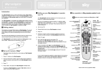
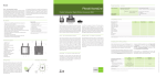
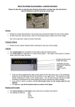
Important reading
before you begin
1. Check the new tvLINK® is functioning correctly by connecting it
directly to the back of the Sky Digital Set-topBox. Do not use cable for
this test, just the tvLINK® female connector plugged directly into the
RF2 output. Then turn the power ON to RF2 by following the
instructions on page 3. The voltage from RF2 should be at least 8
volts.
2. Be aware that the tvLINK® has a DC block on its male connector.
Therefore, when running any tests, the female connector should
always face the Sky Digital Set-top Box.
The Cable
1. Check that the tvLINK® functions correctly on the cable you are
about to install. Make sure the cable is at the length you will need,
and that you are using the connectors you will be using on completion.
Once the installation is complete, and if the tvLINK® no longer
functions, it’s likely to be the cable run. i.e. bad screening.
2. When Installing a tvLINK® it is important to remember that, where
possible, the cable used should be ‘Double Screened’ satellite grade
cable, e.g. CT100 or the equivalent of.
3. There is no specific length to be used for an install but some cable
lengths can cause the tvLINK® to fail. We have found, in testing, that
these lengths carry harmonics which can interfere with the
tvLINK® signal. Changing the length of the cable run by approx. 3 to
4 metres should cure the problem.
4. Some TVs can run “open circuit”, this is not a defect it’s just the
way the TV is built but it can affect the tvLINK®. Install a piece of
cable between the tvLINK® and the 2nd TV and this should change
the impedance and sure the problem.
5. In tests on 100 metre cable runs we have found that the pictures
begin to degrade before the tvLINK® signals fail.
6. All products installed between the tvLINK® and RFout2 on the
back of the Sky Set-topBox, must pass DC in both directions. i.e. wall
plates, splitters, amplifiers etc. If the LED on the tvLINK® is lit a
wallplate can still stop the return signal from the tvLINK® getting back
to the Sky Set-top Box.
The Connectors
1. Always use the tvLINK® connectors supplied.
(See page 8 for Installation instructions) If this is not possible and
standard UHF connectors are used, it’s advisable to solder all joints to
ensure DC continuity.
1
www.tvlink.co.uk
www.tvlink.co.uk
© globalinvacom Ltd. 2008. Not to be reproduced in full, or in part, without prior permission
© globalinvacom Ltd. 2008. Not to be reproduced in full, or in part, without prior permission
The tvLINK®
Single Installation
1. Make up a new piece of cable, using the tvLINK® connectors
supplied (see page 8 for fitting instructions). Make sure it is
long enough to reach the second TV and that is double screened
satellite grade cable.
2. Switch off and disconnect the Sky Set-top Box from the mains
supply.
3. Install the new cable between the Sky Set-top Box and the
second TV.
4. Connect the female end of the new cable into the RFout2
connector on the back of the Sky Set-top Box.
5. Connect the other end of the
new cable (male) into the
female connector of the
tvLINK® . See fig.1.
6. Connect the tvLINK® into the
back of the second TV, and
position the infrared eye in a
spot where it has a line of
sight to the Sky Remote
Control. See fig.2.
fig.1.
fig.2.
If it does not connect directly i.e. the TV housing does not allow the
tvLINK® to get close enough for a firm fitting, then use a small length
of coax between the two. See fig.3.
Extra piece of cable
fig.3.
7. Return to the Sky Set-topBox, plug it back into the mains and
switch it on.
For tvLINK® single installation diagrams see pages 4-5.
www.tvlink.co.uk
www.tvlink.co.uk
2
© globalinvacom Ltd. 2008. Not to be reproduced in full, or in part, without prior permission
© globalinvacom Ltd. 2008. Not to be reproduced in full, or in part, without prior permission
Section 1
Using the tvLINK
Before you can use your tvLINK® it must be activated
via the Sky Digital receiver. Using the Sky Digital
remote control at the main location, follow the
instructions below to Switch on RFout2 and enable
your tvLINK® .
1. Press the SERVICES button once.
2. Press the NUMBER 4 button. (System Set-up)
3. Press the 0,then the 1 then the SELECT button.
(Installer menu)
4. Press the NUMBER 4 again. (RF Outlets)
5. Press the DOWN ARROW button once. (outlet
power supply)
6. Press the SIDE ARROW button once, turning
power on.
7. Press the DOWN ARROW button once again.
(save new settings)
8. Press SELECT to finish.
The LED on the tvLINK® should now be lit and the Sky
Digital Set-top Box should now be operational from the
second location.
Always press the Blue ‘SKY’ button before you try to
operate the Sky Digital Set-top Box from an other
location.
Note: To use you remote control to operate the second
television, e.g. the volume, please refer to the Remote
Control set-up instructions.
3
www.tvlink.co.uk
© globalinvacom Ltd. 2008. Not to be reproduced in full, or in part, without prior permission
© globalinvacom Ltd. 2008. Not to be reproduced in full, or in part, without prior permission
Enabling RF2
Installation diagrams
tvLINK
2nd location
Main TV
1
From RF1
Aerial IN
From RF2
Dish Input
Sky Digibox
Fig.1
Typical Install for Sky+ set top box
tvLINK
2nd location
Main TV
Aerial IN
From RF1
Dish Input 1
Dish Input 2
From RF2
Sky+
Fig.2
www.tvlink.co.uk
4
© globalinvacom Ltd. 2008. Not to be reproduced in full, or in part, without prior permission
© globalinvacom Ltd. 2008. Not to be reproduced in full, or in part, without prior permission
Typical Install for Sky Digibox
Installation diagrams
Typical Install including a video at the main location
tvLINK
2nd location
Main TV
Sky Digibox/Sky+
RFout 1
Dish IN
RFout 2
Aerial. IN
1
Aerial. IN
Video
Fig.3
Typical install with a video at both locations
Sky+ or Sky HD
2nd location
Aerial. IN
tvLINK
Video
Main TV
Sky Digibox/Sky+
31
RFout1
Dish IN
RFout 2
Aerial IN
Aerial IN
Fig.4
Video
5
www.tvlink.co.uk
© globalinvacom Ltd. 2008. Not to be reproduced in full, or in part, without prior permission
© globalinvacom Ltd. 2008. Not to be reproduced in full, or in part, without prior permission
Sky+ or Sky HD
Solving Problems
No Sky channels available at the main TV:
No TV channels available at the main TV:
Check that the coaxial cable from the TV aerial is correctly connected
into the Sky Digital Set-top Box, as per the Sky Digital user manual.
No terrestrial or Sky channels available at the second TV:
Check that the new coax cable is correctly connected to the RF out 2
on the back of the Sky Digital Set-top Box, and that the other end of
the coax is connected to the female connector of the tvLINK® .
Check that the tvLINK® is correctly connected to the aerial socket on
the second TV and that the TV is correctly tuned in. If you are unsure
of how this is done please refer to the TV manual.
Unable to tune in the Sky Digital pictures, or sound, at the
second TV:
Changing the RF channel Number:
Using the Sky Digital remote control at the main location follow these
instructions:
1. Press the SERVICES button once.
2. Key in NUMBER 4 (System Set-up).
3. Press the 0 then the 1 then the SELECT button. These three
buttons are a command which will bring up the hidden
‘Installer Menu’
4. Press the NUMBER 4 button again. (RF Outlets)
5. Change the channel number currently showing as channel 68
(pre-set from the factory).
6. Choose a channel number between 21 and 69 (the most
common being 21, 26, 47 and 69).
7. Press the DOWN ARROW twice followed by the SELECT
button (Save new settings).
8. Finish by returning to the second TV and re-tuning the Sky
pictures back in (please refer to TV manual if you are unsure
of how this is done).
Keep changing the channel, and re-tuning the TV, until you find the
clearest pictures for the area (the 1,5 and 9 rule will apply).
www.tvlink.co.uk
6
© globalinvacom Ltd. 2008. Not to be reproduced in full, or in part, without prior permission
© globalinvacom Ltd. 2008. Not to be reproduced in full, or in part, without prior permission
Check that the dish cable is correctly connected to the dish input on
the back of the Sky Digital Set-top Box, as per the user manual, and
that the cabling and SCART leads between the VCR, Sky and the
main TV are all properly connected.
Solving Problems
Check the red LED is lit on the tvLINK®. This can be found on the
box that plugs into the aerial socket on the back of the second TV. If
the LED is not lit, complete the following:
Disconnect the tvLINK® from the back of the second TV. Unplug it
from the cable and take it to the main location. Connect it directly
onto the back of the Sky Digital Set-top Box, no cable just the
tvLINK® female connector, into RF out 2. Make sure the tvLINK® is
the right way round by checking that the LED is furthermost away
from the Digital Set-top Box.
If the LED does not light up then enter back into the Installer Menu,
page 6 of this guide, and disable the power to RF2, save the settings,
then enable the power once again and save the settings.
If the LED is now lit you may wish to check that your cable does not
run through any splitters, boosters, amplifiers or wall plates that are
not compatible with the tvLINK®. Also check that the connectors
being used are the ones supplied with the tvLINK® and that they are
fitted correctly. (see tvLINK® Connector Installation on page 11)
Unable to operate the second TV with the Sky Digital
Set-top Box remote control:
If the Sky Digital Set-top Box remote will not operate the volume or
channel change facility of the second TV, please refer to the Remote
Control Set-up Instructions.
Note: Always make sure you begin by pressing the blue
‘SKY’ button at the top of the remote control before you try
to operate the Sky Digital Set-top Box from the second
location.
7
www.tvlink.co.uk
© globalinvacom Ltd. 2008. Not to be reproduced in full, or in part, without prior permission
© globalinvacom Ltd. 2008. Not to be reproduced in full, or in part, without prior permission
Unable to change the channels on your Sky Digital Set-top
Box from the second TV:
Connector Installation
NOTE:
Please follow these instructions carefully
1. Begin by placing the black cap onto the coax cable, first. Cut
away the outer sheathing to reveal the copper braiding and fan this
out around the cable as shown in fig.1
Fig.1
2. Cut away the centre dielectric, (white plastic) so that it stands
proud from the end of the cable approx. 1mm. This will reveal the
copper centre pin (approx. 8mm long) As shown in fig.2
Fig.2
Approx. 8mm
Approx. 1mm
3. Push the centre pin up inside the silver part of the connector
until it sits tight against the white plastic. If you can still see the
centre pin then trim it back slightly and try again. As shown in Fig.3
Fig.3
Make sure the outer braiding does not cross the
base of the centre pin, thus causing a short circuit.
4. Finish by wrapping the copper braiding around the threaded part
of the silver connector before pushing the black cap over the top of
the whole lot to hold it all in place. See fig.4
Fig.4
If you can pull the connector off the end of the cable it is either, not
fitted correctly, or the cable is poor quality and does not have
enough screening for a tvLINK® installation.
www.tvlink.co.uk
8
© globalinvacom Ltd. 2008. Not to be reproduced in full, or in part, without prior permission
© globalinvacom Ltd. 2008. Not to be reproduced in full, or in part, without prior permission
These connectors are NOT standard coax connectors.
Each connector comes in two parts:
1) The Black Cap
2) The Silver F to UHF connector.