1
Integrator’s Guide
Borrego +
™
HD Component Video / Composite Video /
Analog Audio Preamp Matrix Switch
FCC Notice
NOTE: This equipment has been tested and found to comply with the
limits for a Class B digital device, pursuant to part 15 of the FCC Rules.
These limits are designed to provide reasonable protection against
harmful interference in a residential installation.
This equipment generates, uses and can radiate radio frequency energy
and, if not installed and used in accordance with the instructions, may
cause harmful interference to radio communications. However, there
is no guarantee that interference will not occur in a particular installation.
If this equipment does cause harmful interference to radio or television
reception, which can be determined by turning the equipment off and on,
the user is encouraged to try to correct the interference by one or more of
the following measures:
•
Reorient or relocate the receiving antenna.
•
Increase the separation between the equipment and receiver. —
•
Connect the equipment into an outlet on a circuit different from
that to which the receiver is connected.
•
Consult the dealer or an experienced radio/ TV technician for
help.
2
Borrego Matrix Switch User’s Guide (DOC42-00027-A_Final.doc)
Table of Contents
Table of Contents ........................................................................ 3 Introduction .................................................................................. 5 Installation .................................................................................... 6 Unpacking ...................................................................................................... 6 Inputs ............................................................................................................. 6 Outputs........................................................................................................... 7 RS-232 Serial ................................................................................................. 7 USB Serial ...................................................................................................... 7 Rear Panel IR ................................................................................................ 7 Power .............................................................................................................. 8 Rack Mounting .............................................................................................. 8 Operation ...................................................................................... 8 Front Panel Control ...................................................................................... 8 IR Remote Control ........................................................................................ 9 Matrix status ............................................................................................. 10 Setup Menu ................................................................................ 10 Using the IR remote or Front Panel .......................................................... 10 Setup Options .............................................................................................. 11 Memory Function ....................................................................... 12 Tone and Volume Control ......................................................... 13 Discrete IR Codes ...................................................................... 13 Restoring to Factory Defaults .................................................. 14 Serial Protocol ........................................................................... 15 Serial Port Settings ................................................................................... 15 Common Structures and Syntax ............................................................... 15 Maximum Response Time........................................................................ 15 Group Commands .................................................................................... 16 Response to Commands ........................................................................... 16 Errors ........................................................................................................ 16 3
Borrego Matrix Switch User’s Guide (DOC42-00027-A_Final.doc)
Switching Protocol ...................................................................................... 17 Command Types ...................................................................................... 17 Input ......................................................................................................... 17 Volume/Bass/Treble Value ...................................................................... 18 Output ....................................................................................................... 18 Time (Optional Field) ............................................................................... 18 Volume Only Commands ......................................................................... 19 Serial Control Examples ............................................................................. 19 Memory Protocol......................................................................................... 20 Setup Protocol ............................................................................................. 22 Power Control ............................................................................................. 23 Query Commands ....................................................................................... 23 USB Driver Installation .............................................................. 24 USB COM Port Settings ............................................................................. 32 Uninstalling the USB drivers ...................................................................... 33 Care and Maintenance............................................................... 33 Specifications ............................................................................ 34 Performance ................................................................................................ 34 Power ............................................................................................................ 34 Physical ........................................................................................................ 34 2 Year Warranty ......................................................................... 35 4
Borrego Matrix Switch User’s Guide (DOC42-00027-A_Final.doc)
Introduction
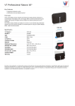
Congratulations on your selection of the Borrego+ audio/video matrix
switch. The Borrego family of matrix switches feature component video
and digital audio in an 8x8 configuration.
Features
•
8 inputs of component video (YPbPr), composite video and
analog audio. The composite video section can also be used for
SPDIF digital audio
•
Volume, Bass and Treble control for Analog Audio outputs
•
16 memory locations to store switch configurations and
volume/bass/treble levels
•
Variable duration volume fade up/down and muting
•
Discrete IR codes for volume and mute for each output
•
High bandwidth video section (140 MHz) for 1080p
•
Independent routing of all signal types
•
Attractive enclosure featuring brushed aluminum and high gloss
acrylic front, with black top cover
•
Universal AC input power, 90-240VAC 50/60Hz with standard
IEC320 receptacle
•
All gold plated RCA connectors ensure a long life without
corroded connectors
•
Ability to add more features in the future via a firmware
update.
5
Borrego Matrix Switch User’s Guide (DOC42-00027-A_Final.doc)
Installation
The Borrego+ Matrix Switch has small cooling vents on the side that
must not be covered, but it can have other equipment such as amplifiers
stacked on top of it. The Borrego is also equipped with removable
padded feet so it may be stacked on top of other equipment without
causing damage.
Unpacking
The Borrego+ ships with the following:
1 – Borrego Matrix Switch
1 – AC Power cord
1 – 6’ USB cable
1 – 6’ RS-232 cable
1 – User’s Guide
1 – CD-ROM driver disc
1 – Pair of rack mount ears with screws
A Neopro IR remote control (if purchased as an accessory).
There is a clear film to protect the front panel. To ensure proper touch
panel response, remove this film before using the Borrego+.
Inputs
Connecting source devices to the Borrego can be done in any order, but
make sure to connect the video “Y”, “Pb” and “Pr” signals as labeled on
the rear panel.
The connectors labeled “Video” are used for composite standard
definition video, or SPDIF digital audio. They can also be used for both
signal types simultaneously, as long as care is taken not to route a signal
of one type to an output of a different type.
The analog audio stereo matrix is labeled “L” and “R”.
6
Borrego Matrix Switch User’s Guide (DOC42-00027-A_Final.doc)
Outputs
Having a true matrix switch allows you to treat each output as a ‘zone’.
For example, Output 1 can be the home theater zone, and output 2 can be
the master bedroom zone. In this case you would run a set of component
video cables plus audio cables to each zone. The maximum length of
cable to each zone will vary on the quality of the cable used. High
quality quad-shielded RG6 cables can support zones 300 feet away.
RS-232 Serial
The serial port on the rear panel is labeled “RS-232”. It is wired as a
DCE device, and should be connected to a PC RS-232 port with a
straight through cable. Connection to most (most?) control systems
should be with a straight through type serial cable, such as the cable
provided with the matrix switch.
For the command protocols, see the Serial Protocols section.
USB Serial
To use the USB communication feature of the Borrego, connect the USB
cable to the PC’s USB port (flat end), and the other end (square end) to
the Borrego matrix switch. See the Serial Protocol and USB Driver
Installation sections of this manual.
Rear Panel IR
The rear panel IR connector is used for direct connection to an IR control
system. It is a 3.5mm 2 conductor jack, and accepts unmodulated IR. It is
polarity insensitive, however normally the ‘tip’ is the active signal, and
the ‘sleeve’ is the ground.
Note: Some IR repeater systems are designed to work only with their
own IR blasters, and a common “workaround” is to cut these blaster
cables and add a 3.5mm plug on the end. In some cases this will work
fine, however some repeater systems will have noise that prevents
signals from being decoded.
7
Borrego Matrix Switch User’s Guide (DOC42-00027-A_Final.doc)
Power
Once all the input and output connectors are installed, connect the
supplied power cable to the AC input. If you are not in North America,
you may use your own standard IEC320 power cable with the Borrego
matrix switch. The power supply input is auto-ranging from 90 to 240
Vac.
Rack Mounting
To prevent shipping damage the product ships with the rack mount ears
detached from the unit. The bottom of the unit has protective feet with
soft, non-scratching pads, so it may be used in a stand-alone mode,
without scratching shelves or equipment it is placed on top of.
In the rackmount configuration, the chassis is 2 rack units high after the
bottom feet are removed. Removal of the feet requires a Philips
screwdriver.. Use the supplied screws to attach the rack ears.
Operation
Overview
The Borrego+ matrix can be thought of as three matrix switches in one
box: 1) A component video matrix, 2) a standard definition composite
video matrix, and 3) an L/R analog audio matrix. By default they are
controlled together, but by using the audio and video commands
mentioned below, they can be controlled separately.
Front Panel Control
The matrix switch front panel uses NeoTouch™ technology. The
NeoTouch™ panel senses a human finger touching the acrylic panel
without any moving parts. When pressed, the button will be illuminated.
A single touch of the power button turns the unit on.
To prevent accidental power down, two button presses are required to
shut down the matrix (standby mode).
8
Borrego Matrix Switch User’s Guide (DOC42-00027-A_Final.doc)
When powered on, three buttons are enabled to start a switching
command: In, Audio, and Video. Control via the front panel is a fourbutton sequence:
1. (In/Audio/Video)
In – Switches both audio and video
Audio – Switches the Audio matrix only
Video – Switches both the component and composite video
2. (Number)*, To select the source input.
3. (Out)
4. (Number)* To select the output or zone
*The panel will not allow you to select inputs or outputs that do not exist
(i.e. “9”).
There are two features that use 0 for the (Number) entry:
Disabling an Output
Selecting Input 0 will disable the output that is selected.
Example: In, 0, Out, 5 will disable audio and video in zone 5.
Party Mode
Selecting Output 0 will route the selected input to all outputs. Example:
In, 3, Out, 0 routes input 3 to all 8 outputs.
IR Remote Control
The command sequence for controlling the matrix switch signal routing
from an IR remote control is similar to front panel sequences, except the
composite and component video can be addressed separately (the front
panel has only one “Video” button). See the previous section
“Controlling from the front panel” for details.
IR Control Sequence
(Video1), (#), (Out), (#) – Controls YPbPr matrix
(Video2), (#), (Out), (#) – Controls composite video matrix
(Audio1), (#), (Out), (#) – Controls analog audio matrix
9
Borrego Matrix Switch User’s Guide (DOC42-00027-A_Final.doc)
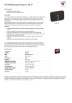
Matrix status
To view the connection status of the matrix, use the IR remote left and
right arrow keys. Each screen will show the current status of one output
(see figure 1). The first line of the display is the output number, and the
second line lists the inputs that are currently connected to that output. In
some cases, the input numbers may be different, indicating that audio
and video have been switched separately. To view another output status,
use the left and right arrow keys to as needed.
At any time the user may press EXIT to return to the home screen, or
wait 10 seconds and the home screen will return on its own.
<
V:1
Output 1
D:1
A:1
>
C:1
Figure 1
V: Component Video
D: Digital Audio
A: Analog Audio
C: Composite Video
Setup Menu
The user setup menu is accessible using the Neopro IR remote,the front
panel, or serial ports (refer to the Serial Protocols section for details).
Using the IR remote or Front Panel
Press “Setup” to open the menu.
Use the “Left” and “Right” arrow buttons to navigate through the
different options (see below for details) and the “Up” and “Down” arrow
buttons to change any of the optional settings.
Use the “Left” or “Right” arrow to save the changes and proceed to the
next setup option.
To quit the Setup menu, there are two options:
Pressing “Select” saves the changes.
Pressing “Exit” discards the changes made to the current option.
The Setup Menu also auto-exits after being idle for 30 seconds.
10
Borrego Matrix Switch User’s Guide (DOC42-00027-A_Final.doc)
Setup Options
SET: Panel LED
This option controls all the front panel LEDs.
The default is ON.
SET: Disp Lamp
Sets the display brightness to one of four levels. The default is 100%
(full brightness).
SET: AC PowerUp
This option controls what the matrix will do when AC power is first
applied, and how it recovers from a power outage. Selecting “ON”
(default) will force the unit to turn on, and the previous switch state will
be restored. Selecting “STANDBY” will cause the unit to enter standby
mode when AC power is applied.
SET: Touchpanel
This option enables or disables the front panel buttons.
The default is “ON” (enabled).
SET: Touchsense
This controls the sensitivity of the front panel buttons.
Default is “HIGH” and this makes the front panel respond faster. A
lower setting reduces the risk for accidental button pushes or false
triggers by outside interference.
SET: Front IR
This option enables or disables the front panel IR sensor. Set to OFF to
prevent spurious IR signals from controlling the matrix.
The default for the front IR is “ON (enabled).
SET: Verbosity
Memory commands and mute commands will always echo serial
responses, regardless of this setting.
The default for this option is ON, where the matrix echoes responses to
any command (via RS-232, IR, or front panel). When set to OFF, the
matrix only echoes responses to RS-232 commands.
11
Borrego Matrix Switch User’s Guide (DOC42-00027-A_Final.doc)
Volume Presets and Preamp
The range for all bass, treble and volume levels is “00” to “99”. The
matrix switch is shipped with default volume set to 25%, and bass and
treble set to 50%.
If you are not going to use the preamp function of your matrix switch, set
the audio preamp for a flat audio response (the output level will match
the input level). Set the volume to “99” and bass and treble to “50”
(bass and treble “neutral”—no boost or cut).
?>>If any of the output volumes were changed (i.e. not anymore at max),
you can activate this option again. The “Use Current” option will not
change any of the volume settings.
Memory Function
The matrix switch has 16 available memory slots (1-16). Each memory
slot can store the state of the switch and is editable using the serial
protocol. Storing and recalling to and from a memory slot is done easily
using the IR remote.
Shortcuts: “#” may be 1 or 2 digits depending on the slot no. Leading
zeroes are not required for slots 1-9.
(Stop), (#) – Store current switch state to memory slot #
(Play), (#) – Recall memory slot # and overwrites current switch
state
Memory view and edit can only be done via the serial port. You can
make a backup of all memory slots by using memory view and save them
in a text file. Please refer to the Serial Protocol section of this manual.
12
Borrego Matrix Switch User’s Guide (DOC42-00027-A_Final.doc)
Tone and Volume Control
Tone and volume control can be accessed through the front panel, IR
remote, or serial (see Serial Protocol section in this manual).
Press “VOL+TONE” button from the front panel or “INFO” button on
the IR remote to access the tone and volume control menu.
Use the “LEFT” and “RIGHT” arrows to change output numbers.
Use the “UP” and “DOWN” arrows to increase or decrease value.
For bass and treble, 50 is used for a “flat” frequency response. Maximum
is 99 and minimum is 00.
Press “SELECT” to switch between Volume, Bass, or Treble.
Quit (via front panel) by pressing “VOL+TONE” button or powering the
unit down. To quit with the IR remote, press the “EXIT” button.
Discrete IR Codes
You may download the discrete IR codes from our website:
http://www.neoprointegrator.com.
The codes come in multiple formats.
13
Borrego Matrix Switch User’s Guide (DOC42-00027-A_Final.doc)
Restoring to Factory Defaults
If you accidently disable the front panel or IR input via the USB or RS232 port, you may restore those features without using the ports again.
The factory defaults may be restored using the steps below.
CAUTION!
Restoring to factory defaults wipes out all switch settings, volume and
tone settings, setups, and memory slots. Make sure you have a backup of
these. Use the query commands (see Serial Protocol section in this
manual) and save the responses in a text file.
To restore the Borrego+ matrix switch back to factory defaults:
•
Place the Borrego+ in standby mode by pressing the power button.
•
On the front panel, slowly press 0, 0, 7.
The unit will then enter Initialization, and when complete, return to
“ON” mode. The front panel and IR will work normally.
14
Borrego Matrix Switch User’s Guide (DOC42-00027-A_Final.doc)
Serial Protocol
Commands
Commands are structured so that a control program has two-way
communication with the matrix. The control system can confirm and
store the state of the matrix switch. These commands are also human
readable ASCII text, which will help in troubleshooting and testing.
The matrix may also be controlled with one way serial communications.
Some models have the ability to switch audio and video separately. For
these switches, the matrix looks like several independent switches. These
“levels” are also called Command Types.
Serial Port Settings
115.2 kilobaud, no parity, 8 data, 1 stop.
Common Structures and Syntax
Commands are not case sensitive. Upper and lower case characters are
used in this manual, but have the same effect. Numbers are 1 or 2 digits,
(leading zeroes not required). Spaces are not permitted within the square
braces—they will generate an error (see Error section).
A command is always wrapped in square braces:
[command]
It is not necessary to follow the command by any carriage returns or
other special characters. The closing brace will trigger the switch to
process the command. Within a command or response, there will be one
or more fields, separated by commas:
[BV,1,2]
Maximum Response Time
Delays are not required between individual commands or group
commands for sending up to 32 commands at a time to the matrix switch.
For more than 32 commands, wait 500ms before sending.
15
Borrego Matrix Switch User’s Guide (DOC42-00027-A_Final.doc)
One Way Serial Hints
Any of the examples shown in this guide can be sent to the matrix at
anytime without concern as to the state of the matrix. If you need to send
a string of commands, put them in a Group Command.
Group Commands
A group command is always wrapped in curly brackets:
{[command1][command2][command3]}
Group commands are used if the user wants to see one response per
command mode inside the group brackets. So if there are two volume
commands in one group bracket, there will only be one volume response.
Example:
Group commands are also used for memory edit function, this will be
discussed later.
Response to Commands
The serial port does not echo characters sent.
When a command is sent, the matrix switch response will be in curly
brackets, like in a group command. That way, any response from the
switch can be used as a command back to it. The contents depend on the
type of command and the model. When signal paths are switched, code
indicating the status of the entire matrix is returned. Refer to the “Query
commands” section for the specific matrix switch model for more details.
Errors
Any command with a syntax error will result in a response of
[E]
The switch will only attempt to process a command between matching [
] braces, so any characters before and after the braces is thrown
discarded. If invalid characters are between the braces, they will be
processed, and the switch will echo the bad command and return an
error.
16
Borrego Matrix Switch User’s Guide (DOC42-00027-A_Final.doc)
Switching Protocol
Switching commands use this structure
[mc,i,o,t]
m is the first letter of the model name (e.g. “b” for Borrego)
c is the Command Type (see below)
i is the Input number or Volume/Bass/Treble Level
o is the Output number
t is the Time (optional for delays, fades, etc.)
Command Types
X to switch All A/V Signals
V to switch High Definition Video (YPbPr)’
D to switch Digital Audio (SPDIF)
A to switch Analog Audio (L/R stereo)
C to switch Composite Video
L toSet Volume Level
B to Set Bass Level
T to Set Treble Level
Note: Some matrix switch models do not have all these levels enabled
and will display the error [E] response when such a command is
received.
Example: The Delano (video only matrix), has one level, HD Video. So
D A C L B T are not valid command types, and will generate errors.
Input
Source input range is from 0 to maximum number of inputs. Please refer
to the user manual to determine maximum number of inputs and outputs.
This may be one or two digits--no leading zeros required. Selecting Input
0 will disable the selected output zone
17
Borrego Matrix Switch User’s Guide (DOC42-00027-A_Final.doc)
Volume/Bass/Treble Value
Valid values ranges from 0 to 99 (max.). “Flat response” settings are:
Volume = 99 (no gain from input to output)
Bass, Treble = 50. Greater than 50 boosts and less than 50 attenuates the
respective tone.
Output
Output zone range is from 0 to maximum number of outputs.
Output ‘0’ sends the selected input to all output zones (Party Mode).
Time (Optional Field)
The time parameter is used to smooth transitions between volume levels.
It may be used to minimize “pop” or sudden noises when switching
audio sources.
The format for commands using the time parameter is:
[mc,i,o]
where:
m is the first letter of the model name
c is the Command Type.
i is the Input number.
o is the Time (0 to 10 seconds for transition).
For a switch command, time is split for ramping down and ramping back
up. So for a time 10, 5 seconds is spent ramping the volume to 0, then
switching occurs and the level ramps to the current level over 5 seconds.
For lower volumes, the matrix switch will not wait for the time to expire,
which means switching can happen faster once the target volume is
reached.
Some command types do not fade in or out of the time field.
V (YPbPr video), C (composite video), D (digital audio) will perform
the switch at the middle of the time interval, so for a time setting of 8, the
video will switch at 4 seconds without any fade-in or out.
B (bass) and T (treble) will not be affected by time settings, and no error
will be generated.
18
Borrego Matrix Switch User’s Guide (DOC42-00027-A_Final.doc)
Volume Only Commands
These commands only affect audio:
x is the first letter of the model name (e.g. “b” for Borrego)
n is the Output number
[xL,M0,n] – Absolute mute output n (absolute = 0)
[xL,MP,n] – Partial mute output n
[xL,U,n] – Volume UP output n
[xL,D,n] – Volume DOWN output n
Serial Control Examples
[BV,1,2]
Borrego matrix: Routes HD Video input 1 to output 2
[GX,0,0,3]
Gillespie: Disable all outputs in 3 seconds.
{[EL,99,1][eb,99,1][et,99,1]}
Eureka : (Group) Set volume, bass, and treble to 99 for output 1.
[CL,M0,0]
Concord : (Group) Mute (absolute) all outputs.
19
Borrego Matrix Switch User’s Guide (DOC42-00027-A_Final.doc)
Memory Protocol
Memory functions enable the user to store, recall, view, and edit switch
configurations. There are 16 memory slots available.
The Memory Command structure begins with “M”:
[M,x,n]
x
n (memory location)
Function
S
1-16
Store current state to memory location n
R
1-16
Recall memory location n
V
1-16
View memory location n via serial
C
1-16
Clear memory location n
E
1-16
Edit memory location n
Memory function stores volume, bass, and treble values, and all inputoutput combinations in the matrix switch. . Fading time cannot be stored
in memory using [M,S,n]. Instead, user can use memory edit function to
store the time field.
Example: If you want to have a paging setup to save the current
configuration, switch all outputs to input 1, set all volumes to 99, and
then restore the saved configuration once the paging is done the macro of
commands is:
[M,S,1]
{[BA,1,0][BL,99,0]}
…do your paging…
[M,R,1]
20
Borrego Matrix Switch User’s Guide (DOC42-00027-A_Final.doc)
Memory Edit
Memory edit allows the user to modify the current stored memory from
any memory location. To do this, invoke the memory edit function
[M,E,n], then send switch commands using the group brackets. These
commands will be stored in the memory location, but will not be
executed
These commands must be inside a pair of curly brackets:
{ [][][][]… }
They can have a time field and will be stored in memory. Any error
command inside a group bracket while memory edit command is active
will be ignored.
Succeeding commands after the end bracket ‘}’ will be treated as normal
commands. If no opening bracket is detected right after memory edit was
invoked, and another command was detected (valid or not), it will be
ignored and the program will exit memory edit function without saving
anything to that memory location. The Memory edit function only
accepts switch commands.
21
Borrego Matrix Switch User’s Guide (DOC42-00027-A_Final.doc)
Setup Protocol
Command structure prototype begins with “S”:
[S,x,n]
x
n
Output
L
0
Led OFF
L
1
Led ON
R
0
IR OFF
R
1
IR ON
B
0
Front Panel Buttons OFF
B
1
Front Panel Buttons ON
V
0
Verbosity OFF
V
1
Verbosity ON
D
25
Display Brightness 25%
D
50
Display Brightness 50%
D
75
Display Brightness 75%
D
100
Display Brightness 100%
S
L
Front Panel Sensitivity
LOW
S
M
Front Panel Sensitivity
MEDIUM
S
H
Front Panel Sensitivity
HIGH
A
0
On Power Up –
STANDBY
A
1
On Power Up – ON
22
Borrego Matrix Switch User’s Guide (DOC42-00027-A_Final.doc)
Power Control
To Power ON use:
[P,1]
For Power OFF use:
[P,0]
Query Commands
Query commands begin with “?” and return current states. Responses are
enclosed in curly brackets. They can be re-used as input back to the
matrix switch. Queries only respond to valid command types and levels.
Example: For the Delano matrix, [?DA] is invalid. because it does not
have an Analog Audio (A) command type or switch level. The query for
all levels, [?D] or [?DX] will only return HD Video (V) responses.
x = model letter
[?S] – Setup
[?P] – Power
[?V] – Version
[?x] – All levels Switch State (X, V, D, A, C)
[?x0] – All levels Switch State (X, V, D, A, C)
[?xX] – All levels Switch State (X, V, D, A, C)
[?xV] – HD Video Switch State (V)
[?xD] – Digital Audio Switch State (D)
[?xA] – Analog Audio Switch State (A)
[?xC] – Composite Video Switch State (C)
[?xL] – Volume (L)
[?xB] – Bass (B)
[?xT] – Treble (T)
23
Borrego Matrix Switch User’s Guide (DOC42-00027-A_Final.doc)
Model Specific Queries
For Avalon, Borrego, Concord only:
[?x1] – HD Video Switch State (V)
[?x2] – Avalon = Digital Audio Switch State (D)
[?x2] – Borrego/Concord = Analog Audio Switch State (A)
For Borrego and Concord only:
[?x3] – Composite Video Switch State (C)
USB Driver Installation
When using the USB port, the matrix switch will be installed as a virtual
COM port. This means that any control program capable of controlling a
device through a normal serial port should be able to control the matrix
through a USB port.
This driver set is for all versions of MS Windows. Linux and Mac drivers
can be made available upon request.
The following steps are for Windows XP, but other versions of Windows
are similar.
Step 1 – Connect the USB cable to the matrix and controlling computer.
Windows will detect the new hardware, and launch the plug and play
wizard.
24
Borrego Matrix Switch User’s Guide (DOC42-00027-A_Final.doc)
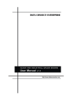
Step 2 – Found New Hardware Wizard
The first window will attempt to use the internet to find the driver, Select
“No, not at this time”, and click Next.
25
Borrego Matrix Switch User’s Guide (DOC42-00027-A_Final.doc)
Step 3 – Driver location
The next window attempts to find the driver disc. Insert the driver CD
disc in the your CD-ROM drive if you haven’t already.
Leave the button labeled “Install the software automatically
(recommended)” selected, and click Next.
26
Borrego Matrix Switch User’s Guide (DOC42-00027-A_Final.doc)
Step 4 – Continue Anyway
Windows will prompt on logo testing. Click “Continue Anyway”
27
Borrego Matrix Switch User’s Guide (DOC42-00027-A_Final.doc)
Step 5 – Completion of first half
Click “Finish”.
28
Borrego Matrix Switch User’s Guide (DOC42-00027-A_Final.doc)
Step 6 – Installing virtual COM port driver
Windows will again start the new hardware wizard to install the virtual
COM port driver. Click “No, not this time”, then click Next.
29
Borrego Matrix Switch User’s Guide (DOC42-00027-A_Final.doc)
Step 7 – Finding the driver
Leave the button labeled “Install the software automatically
(recommended)” selected, and click Next.
30
Borrego Matrix Switch User’s Guide (DOC42-00027-A_Final.doc)
Step 8 – Continue Anyway
Windows will prompt on logo testing. Click “Continue Anyway”
Step 9 – Completing the Hardware Update Wizard
This is the final step, click Finish
At this point, the drivers are installed properly.
31
Borrego Matrix Switch User’s Guide (DOC42-00027-A_Final.doc)
USB COM Port Settings
Whether using a Windows terminal program such as Hyperterminal, a
control application, or a dedicated control system, the baud rate settings
are the same: 115200 baud, 8 data, no parity, 1 stop, no flow control. The
COM port shown in the following example may change depending on
your system.
32
Borrego Matrix Switch User’s Guide (DOC42-00027-A_Final.doc)
Uninstalling the USB drivers
There is typically no harm in leaving the drivers installed in Windows. It
is usually best to keep them installed, so that when the device is plugged
back in, it will be recognized automatically and is assigned the same
COM port number.
However, if you need to uninstall the drivers for any reason, use the
Windows Control panel to do so.
To Uninstall:
Click the Start Menu
Select Settings, then Control Panel
Click Add or Remove Programs
Find Matrix Switch USB Drivers
Click Change /Remove
Follow the on screen instructions.
Care and Maintenance
The Borrego+ matrix switch does not require any regular maintenance
besides keeping it clean.
Never use harsh cleaners or solvents on the Borrego+ front panel. There
are several dusting products for electronics, and standard glass cleaner
may be used.
Spray any liquids onto a towel first, then wipe the front of the Borrego+
with the moist towel.
Should the Borrego+ matrix switch fail to operate as expected, please
contact NeoPro for service advice. THERE ARE NO ADJUSTMENTS
OR USER SERVICEABLE PARTS INSIDE THE CABINET.
33
Borrego Matrix Switch User’s Guide (DOC42-00027-A_Final.doc)
Specifications
Performance
Component Video
Input coupling
Input impedance/termination
Output coupling
Output impedance
Output video bandwidth (-3dB)
Crosstalk
Video modes
Video vertical rates
AC
75 ohms
DC
75 ohms source terminated
140 MHz
Below –80dB
480i, 480p, 540i, 540p, 576i, 576p,
720p, 1080i, 1080p
24, 25, 29.97, 30, 50, 59.97, 60
Composite Video &
DigitalAudio
Output video bandwidth (-1dB)
Crosstalk
10 MHz
Below –80dB
Audio (Analog L/R)
Input termination
Audio bandwidth
Gain and output type
10K ohms
20-20KHz, +/- 0.5dB
Variable gain (0%= -100bD,
100%=0db), low impedance output
Power
Input voltage
Input power
90-240V AC 50-60Hz autosensing
8W when “On”; 4W in “standby”
Physical
Dim. with feet (removable)
Dim without feet
17”W x 3.75”H x 10.75”D
17”W x 3.55”H x 10.75”D
Weight
8.8 lbs (shipping wt. 13 lbs.)
34
Borrego Matrix Switch User’s Guide (DOC42-00027-A_Final.doc)
2 Year Warranty
NeoPro warrants this product against defects in material and
workmanship for a period of 2 years. This warranty applies to the
original end-user purchaser and installation service provider. NeoPro
will, solely at its option, repair or replace this product with a functionally
equivalent new or factory-reconditioned product during the warranty
period. The consumer should contact the installation service provider that
resold the product who will in turn deliver the product to NeoPro. All
transportation risks and costs in connection with this warranty service are
the responsibility of the consumer.
In order to keep this warranty in effect, the product must have been
handled and used as prescribed in the instructions accompanying this
warranty. This warranty does not cover any damage due to accident,
misuse, abuse, or negligence. Repair or replacement, as provided under
this warranty, is your exclusive remedy. NeoPro shall not be liable for
any incidental or consequential damages. Implied warranties of
merchantability and fitness for a particular purpose on this product are
limited to the duration of this warranty.
Some states/countries do not allow the exclusion or limitation of
incidental or consequential damages, so the above limitation or exclusion
may not apply to you. Some states/countries do not allow limitations on
how long an implied warranty lasts, so the above limitation may not
apply to you. This warranty gives you specific legal rights, and you may
also have other rights that vary from state to state and country to country.
35
Borrego Matrix Switch User’s Guide (DOC42-00027-A_Final.doc)
© 2010 NeoPro
www.neoprointegrator.com
36
Borrego Matrix Switch User’s Guide (DOC42-00027-A_Final.doc)