1
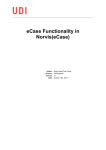
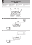
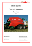
DCU 205 User’s Manual DIESEL ENGINE CONTROL UNIT DCU 205 - USER’S MANUAL - N-2000 Lillestrøm, Norway Tel: (+47) 64 84 52 00 Fax: (+47) 64 84 52 12 [email protected] -1- DCU 205 User’s Manual TABLE OF CONTENTS 1. INTRODUCTION TO THE DCU 205 .....................................................................4 1.1. TYPE APPROVAL CERTIFICATES ...................................................................4 2. TECHNICAL SPECIFICATION..............................................................................5 2.1. IN GENERAL ................................................................................................5 2.2. FUSES........................................................................................................5 2.3. FRONT PANEL LAYOUT ................................................................................6 3. BEFORE OPERATION..........................................................................................7 3.1. CONTROL INDICATOR ..................................................................................7 4. OPERATING THE CONTROL UNIT .....................................................................8 4.1. START BUTTON ...........................................................................................8 4.2. STOP BUTTON.............................................................................................8 4.3. STANDBY BUTTON .......................................................................................8 4.4. MANUAL BUTTON ........................................................................................9 4.5. RESET BUTTON ...........................................................................................9 4.6. SIREN-OFF BUTTON.....................................................................................9 4.7. LAMP TEST BUTTON ....................................................................................9 4.8. HOUR COUNTER..........................................................................................9 5. ALARM CENTRE.................................................................................................10 5.1. IN GENERAL ..............................................................................................10 5.2. NOT USED ALARMS ...................................................................................11 6. SHUTDOWN CENTRE........................................................................................12 6.1. IN GENERAL ..............................................................................................12 6.2. EMERGENCY AND HARBOUR GENERATOR SETS...........................................13 6.3. OVERSPEED ADJUSTMENT.........................................................................13 7. ADJUSTMENTS AND TIMER SETTINGS ..........................................................14 7.1. FRONTPANEL TEXT LABELS ........................................................................14 8. REMOTE CONTROL...........................................................................................15 8.1. MANUAL START AND STOP .........................................................................15 8.2. AUTOMATIC START, DELAYED STOP ...........................................................15 9. TROUBLE SHOOTING........................................................................................16 10. WIRE CONNECTIONS TABLE .........................................................................17 11. SCHEMATIC DIAGRAM ....................................................................................19 -2- DCU 205 User’s Manual Document revisions Date Revision January 1998 March 1997 August 1996 May 1996 March 1996 Release automatic resettable fuses Release v.1.1 Release v1.0 Prototype Created Approved by: • Det norske Veritas (DnV), certificate no. A-6246. • Lloyd's Register of Shipping, certificate no. 96/00095. DnV logo Lloyd's logo Copyright Auto-Maskin A/S, 1994 - 2001 Information given in this specification may change without prior notice. This document should not be copied without permission from AutoMaskin A/S. Description: Revision: august, 2001 User’s Manual order no.: 05012 -3- DCU 205 User’s Manual INTRODUCTION TO THE DCU 205 The Diesel Control Unit type DCU 205, is a unit for control and monitoring of marine diesel engines used as generator sets, main propulsion engines or pumping stations. The unit covers functions such as manual start and stop, automatic start and stop, shutdowns and alarms for the diesel engine. Furthermore, it has built-in functions that make it easy to interface the unit to other control units onboard the ship. DCU 205 is made up of two separate parts, mainly an alarm unit and a control unit. The alarm unit must be powered from the ships alarm centre, and the control unit from the start battery. The alarm unit will operate independently of the control unit. The front panel contains separate indication for alarms and shutdown functions, as well as buttons for start, stop, manual, standby, reset, siren off and lamp test. All inputs are electrically isolated with optocouplers, and the relay outputs can withstand 2 ampère load. The unit is built for console mounting and requires little cabinet depth. It is delivered with a separate wire terminal unit which should be mounted in the cabinet. The cable between these units has snap-on connectors, which ensure quick and easy mounting and servicing. The unit can be placed wherever suitable, or where it feels most natural to control and monitor the diesel engine. It can be fitted in the ship's control console or delivered in a steel enclosure for bulkhead mounting. The unit is robust and has a high degree of dust and water protection, and thus can be placed in the engine room. Type approval certificates The DCU 205 diesel control unit is CE-marked and type approved by the following classification bodies: • Det norske Veritas (DnV), certificate no. A-6246. • Lloyd's Register of Shipping, certificate no. 96/00095. To obtain a copy of the certificates for your documentation, please contact your distributor, or Auto-Maskin directly. -4- DCU 205 User’s Manual TECHNICAL SPECIFICATION In general Supply To control unit, from startbattery To alarm unit, from alarmcentre battery Voltage 20-30VDC 20-30VDC Output relay contact load Operating ambient temperature Max. 125V, 2A 0 - 70°C Current consumption Ca. 100mA Ca. 50 mA DCU 205 unit Cut-out dimensions Overall dimensions Centre distance, mounting holes Total depth Holding screws Total weight Front cabinet protection 188 x 167mm (HxW) 204 x 182mm (HxW) 193 x 172mm (HxW) 67mm M3 - countersunk 900 g IP55 Wire terminal card Overall dimensions Cable length (standard) 40 x 211 x 83 mm (HxWxD) 1.5 meters Steel enclosure version Overall dimensions Total weight (DCU 205 and enclosure) Degree of protection 300 x 300 x 140mm (HxWxD) 4300 g IP44 Fuses A total of 3 automatic resettable fuses are built into the unit. If the fuse breaks, it will reset itself in about 20 seconds. Fuse F1, Circuit fuse F2, Alarm fuse F4, Output fuse Purpose Protects the functions in the shutdown unit. Protects the functions in the alarm unit. Protects the start- and stop signal outputs to the diesel engine. Table 0-Feil! Bryterargument er ikke angitt., The built-in automatic fuses The fuses are of type Raychem Polyswitch ®, RXE040. -5- DCU 205 User’s Manual Front panel layout The Alarm section with replaceable textlabels and one spare field The Shutdown section indicates conditions that will stop the engine Select mode of operation in the Function section Get Status from the Status section The Hour meter indicates engine running hours Figure 0-A, DCU 205 front panel layout The frontpanel is divided into the four sections Alarm, Shutdown, Function and Status. -6- DCU 205 User’s Manual BEFORE OPERATION Before switching on the Control Unit's 24VDC voltage supply, the following should be verified: 1. The switch for selecting the speed sensor type must be set to the right position according to the table below. The switch is located on the back panel. Speed sensor type Tachogenerator Pick-up at the timing gear Pick-up at the flywheel Frequency range 0-80 Hz 0-2 kHz 0-8 kHz Switch position 1 2 3 Table 0-Feil! Bokmerke er ikke definert., Selection of speed sensor type 2. Alarms not in use must be set in the OVERRIDE position. This is accomplished using DIP switch nos. 16, located on the back panel of the Control Unit. For further instructions, please see chapter 0. 3. Shutdown functions not in use should not be connected. 4. Verify all connections. 5. Check that the voltage supply is correct, positive 24VDC on terminal 1 and 39, negative on terminal 2 and 40. See chapter 0 and 0. 6. Make the necessary adjustments as noted under chapter 0. Control Indicator Verify with the Control Indicator on the back panel, that a red and green lamp is flashing. This indicates that the Alarm and Shutdown parts of the unit are activated and operating. A constant light indicates malfunction. Flashing lights indicates the unit is operating: One flashing and one black light normally indicates that power is applied to only one unit. Red: Alarm unit Green: Shutdown unit -7- DCU 205 User’s Manual OPERATING THE CONTROL UNIT The DCU 205 Control Unit is controlled using the seven pressure-sensitive push buttons on the front panel. For remote operation see chapter 0. The functions of these push buttons are discussed underneath. Start button For manual starting of the engine. The start solenoid is activated as long as the button is pressed, but is disabled when the RUNNING signal comes on. The RUNNING signal indicates that the engine has reached ignition speed. The lamp in the start button area lights up when the button is pressed, when a remote start signal is given, or when the Control Unit receives an AUTOMATIC START signal in the STANDBY mode. Stop button The engine will stop immediately when voltage is applied to the stop solenoid connected to terminal no. 9. A brief press on the button is enough to activate the stop solenoid, which is then activated for approx. 50 seconds. The voltage on terminal no. 10, used for run solenoids or as feed voltage for electronic regulators, disappears at the same time. The lamp in the STOP button will light during the stop holding time (the time terminal 9 has voltage), or if the engine has a DELAYED STOP command in STANDBY mode. Standby button Standby START STANDBY is a situation where the Control Unit will try to start the engine three times if an external start signal, AUTOMATIC START, e.g. in the form of a blackout signal, is applied to terminals no. 21-22. The signal must be applied during the entire start sequence, approx. 45 sec., and may then be removed. The lamp in the START button will remain on as long as the AUTOMATIC START signal is present. If the signal is removed, the start sequence will be aborted. Each start attempt lasts 7 seconds followed by a 7-second pause (50% duty cycle). In addition, there is a 2-second delay before the first start. These delays are not adjustable. If three start attempts have elapsed without a successful start of the diesel engine, the AUTOMATIC START FAILED alarm will be activated and the RESET button lamp will come on to indicate that no further starts can be made until the operator has pressed the RESET button. Standby STOP -8- DCU 205 User’s Manual The engine may be given a delayed stop by applying the DELAYED STOP signal to terminals no. 21-23. The engine will then run the pre-set DELAYED STOP time, before the generator circuit breaker disconnect signal is given to terminals 35-36. The engine will then run at idle for a pre-set cooling time before finally stopping. The STOP lamp will remain on as long as the DELAYED STOP signal is present, to indicate that the engine is in the stop cycle and about to stop. If AUTOMATIC START and DELAYED STOP are applied simultaneously, priority is given to AUTOMATIC START. A relay contact will be closed on Control Unit wire terminals no. 33-34 when the Unit is on STANDBY and START DISABLED lamp does NOT light up. These terminals can be used as an indication that the engine is ready for operation. Manual button This button is used to get the system out of STANDBY and into MANUAL. Once this is done, the lamp in the MANUAL area will light up and the automatic start and delayed stop inputs will be blocked. Reset button The RESET button is used to reset all alarms and shutdown functions. In addition, the STOP solenoid holding time will be reset. Alarms with flashing lamps will stop blinking but remain lit to indicate that the alarm has been reset but is still present. If the alarm switch is in normal position before RESET is pressed, the alarm light will turn off. The common alarm relay will return to normal position. Siren-off button The internal siren is activated by any alarm or shutdown. The siren is pulsing if caused by a shutdown situation and continuously if caused by an alarm. The siren is turned off using the SIREN OFF button. This however, does not have any influence on the alarm conditions or relay outputs. Lamp test button Pressing this button will light all the lamps and activate the siren in the DCU 205. Hour counter The LCD counter shows the engine's total running hours, and runs when the RUNNING lamp is on. This is indicated by the blinking hour glass symbol. When the engine is stopped the hour glass lamp remains visible but does not blink. The meter has 1/10 of an hour resolution. It counts up to 99,999.9 hours and can only be reset by the supplier. -9- DCU 205 User’s Manual ALARM CENTRE In general The Control Unit has a total of 9 alarms. Three of these alarms are internally generated by the Control Unit, and the remaining 6 alarms are based on normally closed contacts from the controlled system, i.e., an open contact will set off an alarm. The three internal alarms are: • Supply voltage low • Automatic start failed, and • Speed sensor failure An activated alarm is indicated by its flashing lamp on the front panel. At the same time, the alarm will start the siren and activate the common alarm output relay. The siren can be silenced by pressing the Siren Off button (marked with a symbol) located on the front panel. The alarms are reset by pressing the RESET button. The common alarm relay will return to normal and the flashing lamp will stop flashing but remain lit. This indicates that the alarm has been acknowledged but is still present. The light turns off when the alarm actually disappears. Supply voltage low Alarm is given if the supply voltage drops below 23.5V. Interlocked in 60 sec. and while starting. Failed automatic start After 3 failed start attempts AUTOMATIC START FAILED and COMMON ALARM will appear. Speed sensor failure If the alarm is activated while the engine is running, it is either a broken wire connection or the signal might be too weak. Signal strength can be measured between wire terminals 3 and 4, and should be at least 2.0VAC. If the actual alarm has disappeared before it has been acknowledged (reset), the flashing lamp and the common alarm will remain on until the RESET button has been pressed. All alarm inputs are delayed by 1.5 seconds. The LUB. OIL PRESS. LOW and the extra SPARE alarm inputs are interlocked for 15 seconds after the engine has started, thus these alarms will not be triggered while the engine is stopped. If the alarm is activated when the engine is at standstill, there is a problem with the oil pressure switch (shutdown switch) connected to terminal 5, since it is this signal that - 10 - DCU 205 User’s Manual interlocks the alarm. At the same time, this situation will activate the RUNNING signal and SPEED SENSOR FAIL. Not used alarms Alarms that are not in use must be overridden by switching the DIP switches located on the Control Unit’s back panel to the Override position. Otherwise, these inputs will give an alarm. DIP switch no. 1 2 3 4 5 6 Wire terminal 12 13 14 15 16 17 Alarm Up = Override Down = Normal LUB. OIL PRESS. LOW LUB. OIL TEMP. HIGH COOLING WATER TEMP. HIGH COOLING WATER LEVEL LOW FUEL OIL LEAKAGE SPARE Table 0-Feil! Bokmerke er ikke definert., Overriding alarms that are not in use Please take a moment to mark here which alarms (if any) should be overridden in this particular system. - 11 - DCU 205 User’s Manual SHUTDOWN CENTRE In general The Control Unit recognises up to 4 conditions that will activate engine shutdown. They are: • Overspeed • Lub. oil press. low NO • Cooling water temp. high NO • Spare NO The Overspeed alarm is based upon the speed sensor frequency. The other three are normally open (NO) contact inputs. The LUB. OIL PRESS LOW and SPARE alarms are excluded for 15 seconds after the engine has started, and are excluded if the engine is stopped. An activated shutdown will flash its corresponding alarm lamp and start the siren. The siren can be silenced by pressing the Siren Off button located on the front panel, without resetting the alarm. The shutdown sequence is as follows: • The SHUTDOWN alarm output is activated. • The Emergency Stop system output (wire terminal 11) is activated (OVERSPEED only). • The stop solenoid is activated by applying voltage to terminal 9, and the engine stops. (The solenoid is activated for approximately 50 seconds). • The run solenoid or electronic regulator on terminal 10 is deactivated. • The STOP lamp located in the units FUNCTION area remain on as long as the stop solenoid is activated, or run solenoid is deactivated. • The START DISABLED lamp activates. Any Shutdown is reset by pressing the RESET button. - 12 - DCU 205 User’s Manual Emergency and harbour generator sets When the generator set is used as a combined emergency and harbour generator set, it can be necessary to disable all shutdown functions, except overspeed, when used for emergency power. This function is enabled or disabled using DIP switch no. 7, located on the unit's back panel. When the Control Unit is set in the STANDBY position and DIP switch no. 7 is in the OVERRIDE (ON) position, all the shutdown functions are disabled except for overspeed. If the Control Unit is set in MANUAL, all the shutdown functions are enabled, regardless of the position of DIP switch no. 7. The following table illustrates the situation. Selected Function STANDBY STANDBY MANUAL DIP switch no. 7 OFF ON Don’t care Shutdown Functions Enabled Disabled Enabled Table 0-Feil! Bokmerke er ikke definert., Disabling the Shutdown Functions in Standby mode When shutdown function DISABLED is selected, the three lamps LUB. OIL LOW, COOLING WATER TEMP. HIGH and SPARE will flash simultaneously every 3 seconds, to indicate and remind of this particular selection. Overspeed adjustment The Control Unit activates alarm and shutdown when it detects engine overspeed. Here is how to adjust the overspeed setting to 15% above nominal speed. 1. Set DIP switch no. 8 to the OVERRIDE position. 2. Turn the OVERSPEED SETPOINT potentiometer a few revolutions clockwise. 3. For generator sets, run the engine at nominal speed. For main propulsion engines, run the engine at maximum speed 4. Now, slowly adjust the potentiometer anticlockwise, until the engine stops and the OVERSPEED lamp begins to blink. 5. Important!!! Turn DIP switch no. 8 back to the NORMAL position. The overspeed set point has now been raised 15% above nominal or maximum speed. - 13 - DCU 205 User’s Manual ADJUSTMENTS AND TIMER SETTINGS The table below shows the predefined time delays and the adjustable functions. All adjustments are done on the back panel, see figure. Use a fine screwdriver and a delicate hand when adjusting. Function Delayed automatic start Start and pause intervals during automatic start RUN signal Min. - Max. - Default value 2 sec. 7 sec. Comment Not adjustable Not adjustable 200 600 400 rev/min. Overspeed (rev./min.) 1000 3000 15% above nominal speed Adjustable from back panel Adjustable from back panel. See chapter 0, Overspeed adjustment. Stop solenoid, holding time Delay before disconnecting generator breaker Cooling time 5 180 50 sec. 30 sec. 5 180 30 sec. 0 - 20 mA output for external rev. counter Monitoring delay Alarms delay Shutdown delay 2200 3000 - - 20mA @ 2500 rev./min. 15 sec. 1.5 sec. 1.5 sec. Not adjustable Adjustable from back panel Adjustable from back panel Adjustable from back panel Not adjustable Not adjustable Not adjustable Table 0-Feil! Bokmerke er ikke definert., Table of predefined time delays and adjustable functions. Frontpanel text labels The DCU 205 Control Unit is delivered with the most commonly used wording for alarms and shutdowns. However, there will be situations where other texts may be necessary. New labels can be inserted by sliding the labels into place from the backside of the frontpanel. - 14 - DCU 205 User’s Manual REMOTE CONTROL The Control Unit has wire terminals for two remote start and stop alternatives. • Manual start and stop • Automatic start and delayed stop Manual start and stop The Unit has terminals for remote start and stop. They work in the same way as the local push buttons. Remote Start is connected to terminals no. 18-19. Remote Stop is connected to terminals no. 18-20. Remember, a brief press on the stop button is enough to stop the engine. Automatic start, delayed stop When the Control Unit is set in the STANDBY mode, an internal start/stop program can be activated by means of external signals. Closed contact between terminals no. 21-22 activates start, and closed contact between terminals no. 21 and 23 activates stop. For a more in-depth description of the above, see section 0, Standby, on page 8. - 15 - DCU 205 User’s Manual TROUBLE SHOOTING Symptom 1. The engine does not start manually. Possible cause Action 1. Charge the battery, replace if defective. 2. Wait approx. 20 seconds. 3. RESET alarms. 1. Low battery capacity. 2. Blown fuse. 3. START DISABLED indication. 4. RUNNING indication. 2. The engine does not start automatically. 3. The RUNNING lamp is lit when the engine is stopped and the SPEED SENSOR FAILURE alarm is activated. 4. The SPEED SENSOR FAILURE alarm comes on while the engine is running. 1. Low battery capacity. 2. Control Unit not in STANDBY mode. 3. Missing AUTOMATIC START signal. 1. Lost connection between oil pressure shutdown switch connected to terminal 5. 1. Lost connection to terminal 3 and/or 4. 2. Signal too weak. 5. The common alarm relay is activated without any indication on the control panel. 1. Blown fuse. 2. Control Unit fault. 6. 1. The CIRCUIT fuse is blown. 2. DCU 205 malfunction. Simultaneous alarm for SUPPLY VOLTAGE LOW, SPEED SENSOR FAILURE and AUTOMATIC START FAILED. 4. Check oil pressure switch and its connections, terminal no. 5. 1. Charge the battery, replace if defective. 2. Set the Unit in STANDBY mode. 3. Check connections to terminals 21-22, or the signal source. 1. Check the oil pressure switch and its connections. There should be connection between terminals 2 (negative) and 5 on a stopped engine. 1. Check relevant cables. 2. The signal must be at least 2.0VAC. Adjust or change tachogenerator. 1. Wait approx. 20 seconds. 2. Check that the lamp marked CONTROL on the back panel of the unit is flashing. Turn power off and on again. If the lamp does not flash, contact distributor. 1. Wait approx. 20 seconds. 2. Contact distributor. Table 0-Feil! Bokmerke er ikke definert., Trouble shooting table Further, please verify the following:• Verify that the Control Unit has the correct voltage and polarity. • Make sure the battery is connected in such a way that the Control Unit is sourced from the battery, not the battery charger only. - 16 - DCU 205 User’s Manual WIRE CONNECTIONS TABLE This is a description of all wire connections to the DCU 205 unit. Maximum output relay contact load is 125V, 2A. Terminal no. 1, 2 In/Out In 3, 4 In 5, 6, 7 In 8 Out 9 Out 10 Out 11 Out 12, 13, 14, 15, 16, 17 18, 19 18, 20 21, 22 In 21, 23 In 24, 25, 26 Out 27, 28, 29 Out 30, 31, 32 Out 33, 34 Out 35, 36 Out 37, 38 Out 39, 40 In In In In Comments 24VDC mains, supplied from engine start battery. Also supplies the shutdown unit in the DCU 205. Positive on terminal 1, negative (0V) on terminal 2. From engine speed sensor. Use shielded cable and shield to battery negative (0V, terminal 2), not to ground. Signal strength must be 2-12VAC (pk-pk). Shutdown inputs. 0V in gives shutdown after 1.5 seconds. Input 5 and 7 are interlocked 15 seconds after detected RUN signal. 24VDC output for operating auxiliary start-motor relay. Protected with a 2 amp. fuse. 24VDC output for operating auxiliary stop-solenoid relay. Protected with a 2 amp. fuse. 24VDC output for operating auxiliary run-solenoid or electronic regulator relay. Voltage remains until a STOP command is given. Protected with a 2 amp. fuse. 24VDC output for operating auxiliary emergency stop relay. Not activated during normal STOP. Protected with a 2 amp. fuse. Alarm inputs. If 0V is removed, alarm is given. Input 12 and 17 are interlocked 15 seconds after detected RUN signal. Remote START button. Remote STOP button. Input for automatic start when in STANDBY mode, e.g. blackout signal from main switchboard. Input for delayed stop, e.g. signal from load-dependent start/stop equipment. Voltage free change over contact for Common alarm. 24-25 is NC, 25-26 is NO. Relay deactivates in case of Common alarm. Voltage free change over contact indicating engine running. 2728 is NC, 28-29 is NO. Relay activates when engine running. Voltage free change over contact indicating engine disabled. 3031 is NC, 31-32 is NO. Relay activates if Shutdown is detected. Voltage free contact (NO). If START DISABLED is not given, this indicates DCU 205 unit in STANDBY. Voltage free contact (NO) for generator circuit disconnect. Closes at STOP or when stop delay time has elapsed during a delayed stop. 0-20mA output as a function of engine speed. Positive on 37, negative on 38. Use potmeter at the backpanel to calibrate. Use any correctly scaled 0-20mA meter. 24VDC supply for the DCU 205 alarm section. Supply taken from the alarm centre battery. Positive on terminal 39, negative on terminal 40. Table 0-Feil! Bokmerke er ikke definert., DCU 205 wiring connections The terminal blocks are 2.5mm2. All connections can be made using 0.5mm2 cable, except to terminal 1-2 and 39-40 (power supply) where 1.5mm2 should be used. The diesel engine's terminal box must include auxiliary relays for start and stop, see drawing no. 1205-1, page 19. - 17 - DCU 205 User’s Manual The DCU 205 unit Wire terminal connector - 18 - DCU 205 User’s Manual SCHEMATIC DIAGRAM Figure 0-Feil! Bokmerke er ikke definert., DCU 205 wire connection diagram - 19 -