1
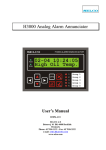
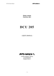
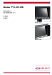
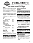
Multiview box
Art no. 0404110
Multiview box Serial
Art no. 0404120
User Manual
No. UM0972190 R2-0
04/2013
English
User manual
User Manual
Multiview box
Art no. 0404110
Multiview box Serial
Art no. 0404120
Manual no. UM0972190 R2-0
Contents
page
1.Introducing3
2.Quad Servive Menu3
3.Channel mode3
4.Camera settings4
5.Camera tags5
6. Advanced settings5
7.Info7
8. Channel mode overview8
9. Version details9
If you have any questions or issues concerning the operation of this
equipment, consult the relevant section in the manual or contact the Orlaco
Products BV Service department.
The camera and monitor systems from Orlaco comply with the
latest CE, ADR, EMC and mirror-directive regulations. All products are
manufactured in accordance with the ISO 9001 quality management, ISO/
TS16949 quality automotive and ISO 14001 environmental management.
For specifications see Data sheets
DS0404110 Multiview box
DS0404120 Multiview box Serial
2
UM0972190 R2-0
User manual
1. Introducing
This user manual describes the Orlaco Multiview box.
Orlaco Multiview box is a video view system for up to 4
cameras PAL or NTSC.
Note: Use only PAL or NTSC cameras. You can not
connect both PAL and NTSC cameras in one system
together.
There are many possibilities of different split views in
5 selectable video channels. After the easy installations
you’ve got an advanced video viewing image for various
camera-system configurations.
2. Quad Service menu
Please first refer to the Orlaco Monitor User Manual for
operating using and the external device configuration
(Ext. device config) selection.
When the Ext. device config is selected you will see the
Quad Service menu, see figure 1.
Figure 2
Choose how the camera views should be shown.
See figure 3.
NOR-mode: full view
ALL-mode: all view
DUA-mode: dual view
TRI-mode: 1-2 top view
REA-mode: 3-1 bottom view
D+R-mode: dual inset top view
SU 1 mode: surround view 1
SU 2 mode: surround view 2
Options for channel 1-4:
1
1
NOR
1
2
3
4
1
ALL
1
2
2
DUA
2
1
3
2
3
Figure 1
Note: To exit the Quad Service menu, press de Option
for 3 seconds.
button
TRI
3
2
REA
1
4
The ‘Quad Service’ menu offers the following possibilities: Channel mode, Camera settings, Camera tags,
Advanced settings and Info. The following chapters will
explain these possibilities.
3. Channel mode
The Orlaco Quad has five camera channels. For the first
four channels you can select a default image layout or
a customer image (chapter 6) layout. Channel five is
always the quad layout, see figure 2.
3
2
D+R
1
4
SU1
SU2
Default channel 5:
1
2
3
4
QUAD
Figure 3
Refer to chapter 8 for a complete overview
Showing the channels: Press the camera button
switch between the channels.
to
Please refer to chapter 6 ‘Advanced channels’ for customize your channel mode.
UM0972190 R2-0
3
User manual
4. Camera settings
This section describes image, tag and marker options.
Note: The camera settings that have already been set
from the monitor will be mixed by the camera settings
which are set in the Multiview box.
The ‘Camera settings’ menu offers the following possibilities for each camera (C1-C4), see figure 4.
Marker pos.
Adjust the horizontal position of the marker. 0 is the top
of the screen, 100 is the bottom of the screen.
Marker col.
Adjust the color of the marker. Adjustable options:
GRN: Green
BLU: Blue
MAG: Magenta
BLA:
Black
RED: Red
WHI: White
YEL:Yellow
CYA:Cyaan
Marker mix
Adjust the transparancy of the marker.
(adjustable options: 0-, 25-, 50- or 100%)
Figure 4
Mirror
Enable this option to mirror the image (left/right)
Upside down
This option reverses the image (flips it upside down)
Tag hor. pos
Adjust the horizontal position of the tag.
(adjustable between 0-100)
Hor. marker2
Enable this option to switch a second marker on. The
marker is displayed as a horizontal default green (color
adjustable) line.
The marker options are the same as the Hor. marker1.
Marker pos.
Adjust the horizontal position of the marker. 0 is the top
of the screen, 100 is the bottom of the screen.
Tag ver. pos
Adjust the vertical position of the tag.
(adjustable between 0-100)
Tag color
Select the color in which the tag should be shown;
(Black, Blue, White, Yellow, Magenta, Red, Cyan and
Green).
Figure 6
Marker col.
Adjust the color of the marker. Adjustable options:
GRN: Green
BLU: Blue
MAG: Magenta
BLA:
Black
RED: Red
WHI: White
YEL:Yellow
CYA:Cyaan
Figure 5
Hor. marker1
Enable this option to switch the marker on. The marker
is displayed as a horizontal default green (color adjustable) line.
4
Figure 7
UM0972190 R2-0
User manual
Marker mix
Adjust the transparancy of the marker.
(adjustable options: 0-, 25-, 50- or 100%)
Brightness
Adjust the brightness of the image
(adjustable between 0-100)
Contrast
Adjust the contrast of the image.
(adjustable between 0-100)
6. Advanced settings
Note: This option shows a menu of settings that
rarely need adjustment and are better left to qualified
technicians.
This chapter describes the advanced settings of language
selection, factory default resetting, channel settings,
Switchwire settings, Communication settings, OSD setting and boundary settings, see figures 10, 11.
Saturation
Adjust the saturation (color intensity) of the image.
(adjustable between 0-100)
5. Camera tags
Figure 10
This section describes how to define the camera textlabels, see figure 8.
Figure 11
Figure 8
In this menu the text-labels for the camera inputs can
be defined.
The number of the tags is depending on the camera
switch option. (For more info please refer to the Orlaco
Monitor User Manual.)
Language
This option opens the language selection menu. See
figure 12. The selected language will be used for all OSD
menus. The OSD menu is available in English, Dutch,
German, French, Czech, Hungarian, Italian, Polish,
Portuguese, Spanish, Turkish, Swedish, Finnish, Danish
and Norwegian.
Select a camera and the option opens the camera tag
editor menu. You can define each camera a name. (max.
6 characters), see figure 9
Figure 12
Figure 9
UM0972190 R2-0
5
User manual
Default settings
Figure 13
W1 priority
Select the window priority, see figure 16.
LOW: lower window
NOR: middle window
HI:
upper window
Note: There’s only one priority high- and one priority
low possible. Make sure that the priority normals do
not overlap each other.
Select defaults
See figure 13. This option opens the factory defaults
menu. Choose the number of the desired factory settings (1=standard Orlaco)
Restore defaults
See figure 14. If the option ‘restore defaults’ is selected,
the factory settings will be reset. Warning: All user settings will be lost when factory defaults are reset.
Channel settings
Figure 16
W1 size
Select the size of the window, see figure 17.
Adjustable options:
1/1, 3/4, 2/3, 1/2, 1/3, 1/4, 1/5, 1/6, 3/4, 2/3, 1/2
Figure 14
Figure 17
Figure 15
The channel settings can be modified. Per channel (CH1CH5) you can choose a window (W1-W4 and define per
window which camera (C1-C4) is shown, see figures
14, 15.
W1 hor. pos.
Determine the window top left horizontal position.
(adjustable between 0-100)
W1 ver. pos.
Determine the window top left vertical position.
(adjustable between 0-100)
W1 on/off
When enabled the window is displayed.
W1 Camera
Select here which camera (C1-C4) should be shown in
this window.
6
UM0972190 R2-0
User manual
Switchwire settings
See figure 18
Boundary settings
See figure 21
These settings are for internal Orlaco use only and
have no function with the orlaco Serial monitor.
Please do not change the settings
Figure 21
Boundary on/off
Turn boundary around video channel on er off.
Figure 18
Comm. settings
See figure 19
These settings are for internal Orlaco use only and
have no function with the orlaco Serial monitor.
Please do not change the settings
Boundary color
Adjust the color of the boundary. Adjustable options:
GRN: Green
BLU: Blue
MAG: Magenta
BLA:
Black
RED: Red
WHI: White
YEL:Yellow
CYA:Cyaan
Boundary blink
Choose wether the boundary should blink or not.
Boundary blink colo
Figure 19
OSD settings
See figure 20
Adjust the color of the boundary blink. Adjustable
options:
GRN: Green
BLU: Blue
MAG: Magenta
BLA:
Black
RED: Red
WHI: White
YEL:Yellow
CYA:Cyaan
7. Info
See figure 22. This option shows Orlaco Multiview box
information. Check in this screen your software version
which is described in this manual.
Figure 20
Menu horizontal pos
Adjust the horizontal position of the menu. 1 is left up
and 16 is right up.
Menu vertical pos
Adjust the vertical position of the menu. 1 is top of
screen and 8 is bottom.
UM0972190 R2-0
Figure 22
7
User manual
8. Channel mode overview
Channel 1
>
Channel 2
>
1
Channel 3
>
2
Channel 4
>
3
4
NOR
mode
1
mode
1
1
2
2
3
4
ALL
1
2
3
3
4
2
2
4
2
3
3
3
4
4
1
mode
2
2
(quad-mode)
1
2
3
4
1
2
3
4
1
2
3
4
1
2
3
4
1
2
3
4
1
2
3
4
1
2
3
4
1
2
3
4
4
DUA
1
Channel 5
>
3
3
4
4
1
TRI
mode
3
4
1
2
1
2
3
2
3
4
4
1
REA
mode
1
3
2
2
4
3
3
4
1
2
4
1
D+R
mode
3
SU1
2
1
4
4
mode
3
3
2
1
1
2
1
4
4
3
2
2
3
2
1
1
4
3
4
3
2
1
4
SU2
mode
4
8
1
2
3
UM0972190 R2-0
>
User manual
9. Version details
Version R1-0. First issue, 9/2010.
Version R1-1. Chapter 8; Channel mode overview added, 7/2012.
Version R1-2. Chapter 3; camera views added, Chapter 6 Advanced settings; settings added, 4/2013.
Version R2-0. Manual number changed, 7/2014
UM0972190 R2-0
9
10
UM0972190 R2-0
UM0972190 R2-0
11
ORLACO
Orlaco is a Manufacturing company that specializes in making cameras and
monitor systems for commercial vehicles, fork-lift trucks, cranes, off shore
and maritime.
Our objective is to design and produce camera systems for the professional
market that improve the drivers view and increase operating efficiency.
At our factory in Barneveld, we have a production department, warehouse,
design department, service department and showroom.
Vision is our mission, and Orlaco therefore deploys the development,
manufacture, supply and service of camera and display systems that will
improve safety and efficiency of all vehicles, machinery and vessels. Our
systems give the end user a view on each blind spot and create comfort
and improved working conditions. Our active approach will support market
demands and innovations and will lead to enthusiastic ambassadors in the
market; our Customers.
For more information: www.orlaco.com
ORLACO PRODUCTS BV
Albert Plesmanstraat 42, 3772 MN Barneveld
PO Box 193, 3770 AD Barneveld
The Netherlands
Phone: +31 (0) 342 404555
Fax:
+31 (0) 342 404556
E-mail:[email protected]
Internet:http://www.orlaco.com