1
Beyond Measure
User Manual and Reference Guide
March 15, 2014
Copyright © 2012 - 2013 Code Zeal
1
Table of Contents
Introduction..........................................................................................................................................5
Application overview.......................................................................................................................5
The Kernel...................................................................................................................................5
The Configuration Tool...............................................................................................................5
The Modules...............................................................................................................................5
Installation............................................................................................................................................6
Prerequisites.....................................................................................................................................6
Selecting a database....................................................................................................................6
Service Configuration......................................................................................................................6
Completing the Installation..............................................................................................................7
Using a Trial License..................................................................................................................7
Installing a purchased license file...............................................................................................7
Starting the Application........................................................................................................................8
General Configuration..........................................................................................................................9
The Supervisor.................................................................................................................................9
Logging............................................................................................................................................9
Advanced debugging.................................................................................................................10
Data Link.......................................................................................................................................10
Database Connections....................................................................................................................11
Data Sources..................................................................................................................................11
Modules..............................................................................................................................................12
Module Communication................................................................................................................12
Messaging Overflow.................................................................................................................12
Module: 1-Wire..............................................................................................................................12
Supported 1-Wire Adapters.......................................................................................................12
Supported 1-Wire Devices........................................................................................................12
Operation and Configuration....................................................................................................13
Operational Settings.............................................................................................................13
Command Priority................................................................................................................14
Setting up adapters and devices............................................................................................14
Adapters and multiple module instances..............................................................................15
Module: Database Storage.............................................................................................................16
Storing tags...............................................................................................................................16
Module: Graph Generator..............................................................................................................18
General requirements and rules for creating a graph................................................................18
Creating Your First Graph.........................................................................................................18
Data Series................................................................................................................................19
Keywords in Legend Texts...................................................................................................20
Examples..........................................................................................................................20
Custom Titles............................................................................................................................20
Keywords and macros in custom titles.................................................................................20
Keywords.........................................................................................................................20
Macros.............................................................................................................................21
Example:.....................................................................................................................22
Module: Mail Gateway..................................................................................................................23
A Word of Caution....................................................................................................................23
Configuration............................................................................................................................23
Copyright © 2012 - 2013 Code Zeal
2
Authentication......................................................................................................................23
Port Numbers........................................................................................................................23
Retrieving Mail.....................................................................................................................23
Configuration Example........................................................................................................24
Google Mail.....................................................................................................................24
Module: Network Binder...............................................................................................................25
Message Distribution................................................................................................................25
A problem: Message Loops..................................................................................................26
Connecting With BM Tool...................................................................................................27
Module: RFXtrx Gateway.............................................................................................................28
Configuration............................................................................................................................28
Data logging..............................................................................................................................28
Module: RaZberry Gateway..........................................................................................................30
Prerequisites..............................................................................................................................30
Supported devices.....................................................................................................................30
Setup..........................................................................................................................................30
Device aliases............................................................................................................................31
Controlling devices...............................................................................................................31
Adjusting configuration options for a device through BM..................................................32
Module: Rule Engine.....................................................................................................................33
The Basics.................................................................................................................................33
A First Example........................................................................................................................33
Schematics................................................................................................................................34
Custom Components............................................................................................................34
Component Library...................................................................................................................34
Components..............................................................................................................................34
Component Properties..........................................................................................................34
Input and Outputs.................................................................................................................35
Pull States........................................................................................................................35
Signal Quality..................................................................................................................35
Circular Connections.......................................................................................................35
Clock Signals...................................................................................................................36
Composite Components............................................................................................................36
Terminals..............................................................................................................................36
Wire breaks...............................................................................................................................37
Live View..................................................................................................................................38
Oscilloscope.........................................................................................................................38
Tag Components........................................................................................................................38
Available Components..............................................................................................................38
Clock outputs........................................................................................................................44
Writing a plug-in for the External component......................................................................53
Creating a Visual Studio project for your external component.................................................53
Module: SMS Gateway..................................................................................................................56
Compatible Devices..................................................................................................................56
Module: Sound...............................................................................................................................57
Text-to-speech Setting...............................................................................................................57
Installing Additional Voices (TTS engines)..............................................................................57
Module: Switch King Bridge.........................................................................................................58
Tag naming................................................................................................................................58
Example................................................................................................................................58
Copyright © 2012 - 2013 Code Zeal
3
Configuration.................................................................................................................................58
Devices...........................................................................................................................................58
Module: Tag Storage......................................................................................................................59
The Concept..............................................................................................................................59
Tags sent between multiple computers.....................................................................................59
The Module...............................................................................................................................59
Module: Tellstick Gateway............................................................................................................60
Requirements............................................................................................................................60
Configuration............................................................................................................................60
Hint................................................................................................................................................61
Module: User Module Engine........................................................................................................62
Development Environment.......................................................................................................62
User Module Development.......................................................................................................62
Life cycle of a User Module.................................................................................................63
Available Message Types.....................................................................................................64
Installing a User Module...........................................................................................................64
Take care when updating BM...................................................................................................64
Module: WebAPI...........................................................................................................................65
Configuration............................................................................................................................65
Configuring to run in desktop mode.........................................................................................65
Provided services......................................................................................................................66
Index Service/Web Server....................................................................................................66
Tag Service...........................................................................................................................66
Configuration...................................................................................................................66
Accessing the service.......................................................................................................66
Module: xAP Gateway...................................................................................................................68
Module: XBMC Bridge.................................................................................................................69
Configuration............................................................................................................................69
Limitations............................................................................................................................69
Usage.............................................................................................................................................69
Cron....................................................................................................................................................70
Fields..............................................................................................................................................70
Field Rules.....................................................................................................................................70
Operators........................................................................................................................................70
Examples........................................................................................................................................70
Copyright © 2012 - 2013 Code Zeal
4
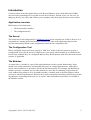
Introduction
Contrary to how most other applications work, Beyond Measure (hence forth abbreviated 'BM'),
does not come prepackaged in a way that it work out-of-the-box. Instead, it lets you, the user, set
things up the way you want, and it allows you to purchase only those parts that you want to utilize.
Application overview
BM consists of two main parts:
•
The kernel and its modules
•
The configuration tool
The Kernel
The kernel runs in the background as a Windows service and is normally not visible to the user. It is
responsible for starting the desired modules (modules are parts of the application that provides
specific functionality) based on the configuration read from the configuration file.
The Configuration Tool
BM is configured using a tool know simply as “BM Tool” which is the only means to prepare a
configuration for use by the kernel. Using this tool, you specify which module(s) to load when the
kernel starts, and how they are configured and how they should operate with each other and external
systems, if applicable.
The Modules
As stated above, a module is a part of the application that provides certain functionality. Some
modules are totally stand-alone, meaning that they have no external dependencies, while others
require other modules to be present to provide the full functionality. For example, the DB Storage
module (provides a common way for other modules to store data in a database) will perform no
work without being asked to do so by another module. A module such as the Rule Engine (which
executes a schema containing user defined rules) can be run totally stand-alone without any external
dependencies (depending on the rule set, of course). More information on modules is available in
the Modules section.
Copyright © 2012 - 2013 Code Zeal
5
Installation
Before you can start using BM, you must first install it onto the computer you wish to run it. Start
by downloading the latest version from the download page, then start the installer and follow the
instructions. Take care to select the upgrade-option if you are performing an upgrade of a licensed
system, otherwise the installer will overwrite your license key with a trial key. Before installing
however, you should make sure that the prerequisites are met.
Prerequisites
BM runs on any 32 or 64bit platform with Microsoft .NET Framework 4 installed (Windows XP
SP3, Windows Vista SP1 or later, Windows 7, Windows Server 2003 SP2, Windows Server 2008
(not Server Core Role), Windows Server 2008 R2 (not Server Core Role) ).
Depending on your functional requirements, you will likely have to install one ore more of the
following items:
•
Maxim’s 1-Wire driver for 1-Wire support. (Be sure to select the correct 32 or 64bit version)
•
ODBC driver for database connectivity.
•
Microsoft SQL Server
•
SQL Server 2005 (section Microsoft SQL Server Native Client, select the x86
or x64 package)
•
SQL Server 2008 (Microsoft SQL Server 2008 Native Client, select x86 or
x64 package)
•
SQL Server 2012 (Microsoft® SQL Server® 2012 Native Client, select x86
or x64 package)
•
MySQL
•
SQLite (this driver is included in the application and does not need separate
installation.
Of course, you will also have a functional database server, should you choose other than
SQLite.
Selecting a database
As a user new to these things, it might be tempting to opt for the SQLite database as it does not
require a separate server installation, but be aware that most users of BM actually uses Microsoft
SQL Server or MySQL since they allow for easier access from other applications and also comes
with more mature configuration and administration tools.
Service Configuration
During installation the kernel is installed as a Windows service (unless you choose not to) and will
run under the local system account. Normally this gives the application sufficient access right to
perform its work, but be aware that network access is limited; network shares etc. are not
accessible.
To configure the service to run as another user (to allow network share access etc.), follow these
Copyright © 2012 - 2013 Code Zeal
6
steps:
•
Open the Services Management Console (Winkey+R, enter “services.msc” and hit Enter.
•
Find the Beyond Measure service in the list.
•
Right-click on and select Properties.
•
Open the Log On tab
•
Select the This account option and enter the account name and password.
•
Press Apply. Please note that the changes does not take effect until the the service is
restarted (done via the General tab).
Completing the Installation
BM comes with a default, empty, configuration so you may opt to configure the application before
starting the service (Winkey+R, enter services.msc, hit Enter then find the service entry and start it)
or, you may start the application in desktop mode by using the shortcut on your start-menu. See
section Starting the Application for more details.
Using a Trial License
The trial license that comes with the license key allows you to load up to four modules, and a run
time of a certain number of hours since the last reboot of of the computer. Note that each module
has its separate time counter, thus each module will stop operations at different times within the
preset time. Once a module considers the trial license to be expired, you have to reboot the
computer before operations can continue.
Installing a purchased license file
When you receive a license file after completing a purchase, simply copy it to the installation folder
and (re)start the service. The application will look for available license files, and select the one with
the latest creation date. Should this search for some reason select the wrong license, such as the trial
license (you can determine this by enabling debug log messages) simply delete the license files that
you do not want it to use.
Copyright © 2012 - 2013 Code Zeal
7
Starting the Application
As noted above, the kernel can run in two modes:
•
Desktop Mode
•
Service Mode
Running in desktop mode has the advantage that you can see the generated log information directly
from within the console window that appears. Regardless of which way you choose, whenever the
configuration file is changed, the kernel will reload it and restart all modules so they can refresh
their settings. Please note that you cannot run the service and in desktop mode at the same time –
only the first instance will be operational.
Copyright © 2012 - 2013 Code Zeal
8
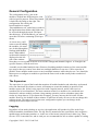
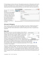
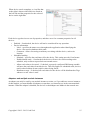
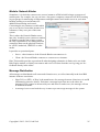
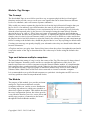
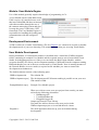
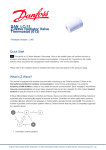
General Configuration
The configuration tool is, just as the
modules, divided into different parts, each
with its specific purpose. When first started,
it looks like the image to the right. The
configuration file read by the
kernel/modules is named
“BeyondMeasure.scb” and always resides in
the applications data-folder (this folder can
be accessed through the menu File/Open
data directory). In all likelihood, you want to
open this file before continuing (File/Open
menu).
As a new user, you'll
want to start by adding
the modules you want
use, do this through the
Settings/Add Module
menu. When added,
each module instance is
displayed on the left
side of the window.
Note that you can expand each item to access the settings that modules support. To configure the
specific instance, click the tool-icon.
A module can be added multiple times. Reasons for adding multiple instances of the same module
type may be that you want to store data in to multiple databases or run two 1-Wire networks in
parallel. Some modules makes sense to run in multiple instances while other do not. Care should be
taken not to to configure to modules to perform the same work as that usually leads to undesired
side effects.
The Supervisor
The supervisor is a part of the kernel that monitors all enabled modules and when they are deemed
to be non-functional for whatever reason, will attempt to restart the module in question. Each
module reports (aka. 'kicks') to the supervisor with a regular interval, and if it does not it is
considered to be non-functional. The most common reason for a module to be considered nonfunctional is when a module performs a long running operation, such as a database query that
results in a large data set. If you know this to happen, you may increase the kick-time for that
module. However, the default of three minutes is sufficient in nearly all cases so do not change this
without reason. The supervisor also has some configuration options you can change in the
Settings/Preferences/Supervisor tab.
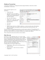
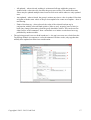
Logging
Regardless of run mode (desktop or service), the application will produce log files in the Logsfolder beneath the installation folder. The log files are named after the current date, their respective
module name and instance number, or, in the case of the kernel, simply Kernel-<date>.log. These
files are UTF-8 encoded files, and as such you are recommended to use an editor capable of reading
Copyright © 2012 - 2013 Code Zeal
9
UF8 encoding (most modern editors do). The application outputs a lot of information to the log files
by default (all four log levels are enabled: Info, Warning, Error & Debug) and the log files are the
first place you should look if you run into problem. It is recommended to let all levels be enabled
during initial setup, then disabling Debug information once the system is taken into production use.
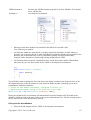
You access the Log settings
through
Settings/Preferences/Logging.
You can select which debug
levels you want to log, and
whether you want to log them
to file and/or Windows Event
Log). You can also change
how and when log files
should be deleted (Windows
Event Log clean-up is
configured using Windows'
own tool).
Advanced debugging
The two options, “Log message count” and “Log debug trace messages” should be used with care
as they can potentially cause a huge amount of data being written to the log files and Windows
Event log. The latter of them should only be enabled if searching for the cause of a problem in the
application.
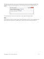
Data Link
Depending on your use case (such as running a schema with live
data), you may want to connect the configuration tool to a kernel
running at either the local or a remote computer. To do this you
must first enable the Network Binder module in the kernel and
configure it to act as a server. Then, open menu Link/Data
link/Connect. You will be presented with the Link Settings
window in which you must enter the IP address or DNS name of
the computer running the kernel. Unless you have changed the port
used by the Network Binder module, leave it at its default of 6001. Once satisfied with the server
address, press enter and the tool will attempt to connect to the kernel through the
Network Binder module. The data link indicator will reflect the link status in the
lower left corner of the window. For information about the Hops To Live-setting,
see Module: Network Binder.
There are two additional menu items under the Data Link menu; “Block all outgoing non-user
commands” and “Request Update”. The former can be used to prevent a schema running in the
configuration tool to interfere with a live system by preventing any command messages being sent
to the kernel. The latter one is a command that causes the modules to report (possibly re-read from
end devices) its current status. This message is also sent on each connect to the kernel so there is no
need to manually issue the command without good reason as it may cause an unwanted load on the
system.
Copyright © 2012 - 2013 Code Zeal
10
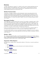
Database Connections
Connections to databases are configured centrally using the Database Connections window
(Data/Database Connections).
Each connection requires a set of
parameters:
•
Connection name
•
Host/Path (in the case of SQLite
databases, you must enter the path
to where the file should reside on
the local computer)
•
Port (not used for SQLite)
•
ODBC Driver (if the driver cannot
be located, it is indicated in the
drop down box)
•
User name
•
Password
•
Database name (in the case of SQLite databases, you must enter the name of the database
file (so the full path to the database becomes the path entered in the Host-filed + the
database name) )
You can click the icon beside drop down box to test the current connection. The application will
attempt to create the database if it does not already exist. Of course, the creation of the database will
only work if the specified user account has sufficient access rights in the database.
These connections can later be used from various modules.
Data Sources
Data Sources (menu Data/Data Sources) are used to define
how to retrieve data from external sources, such as a database,
for use in for graph generation. Each data source requires a
database connection from where the data should be read and
information on how the data should be parsed. There are a
number of templates for different 1-Wire sensors, but you may
also write your own custom SQL queries.
Currently, there are two types of data sources:
•
Graph Sources – these are for use in Data Series in
graph generation.
•
Schema Sources – these are for use in schema
components.
Copyright © 2012 - 2013 Code Zeal
11
Modules
A module (also known as a “plug-in” or “add-on”) can be seen as a separate application, but one
that runs within the same application context as other modules. This separation into functionspecific parts makes it easier to build a system that can be expanded based on the user's need
without adding parts that are not used from the start.
Module Communication
All modules are capable of talking to each other through a common messaging interface; this
enables great possibilities in terms of integration. To the average user these messages are of no
immediate concern, but for those that delve into the User Module Engine, these messages are of
great importance. The kernel handles all message distribution automatically so there is no need to
manually configure it; as long as the module is loaded, it can receive and send messages to/from
other modules.
Messaging Overflow
All messages takes a certain amount of time to process. For example, a command to read a 1-Wire
device takes approximately one second to execute, depending on the network complexity. If you
request it to be read every half second the receiving module, in this case the 1-Wire module, will
start accumulating a number of unprocessed commands, essentially delaying the execution of the
commands. To prevent the system from being flooded, all modules drop messages that are too old
(by default 30 seconds or older) and logs a warning in the module log.
If any of your modules logs such a message, it means that it cannot keep up with the number of
incoming messages and you need to revise your system configuration to lighten the load.
For each separate module, you can set a maximum message age. Although you can set it as high as
a full minute, doing so is not recommended unless you know that a module occasionally is busy for
such a long time.
Module: 1-Wire
The 1-Wire module adds the ability to read and control Maxim's 1-Wire devices. For those that are
not yet familiar with these, Maxim provides a technical but good introduction here. In less technical
terms, a 1-Wire device can be seen as a component with a very specific functionality that is
controlled by a master, in this case the 1-Wire module of BM.
Supported 1-Wire Adapters
BM supports those adapters that are supported by Maxim's 1-Wire drivers, except for parallel port
adapters.
•
Serial: DS9097U
•
DIY/Homebrew adapters (various schematics can be found on the Internet)
•
USB: DS9490R
Supported 1-Wire Devices
•
0x05 – DS2405
Copyright © 2012 - 2013 Code Zeal
12
•
0x10 – DS18S20
•
0x12 – DS2406 (one and two channel versions), DS2407
•
0x1D – DS2423
•
0x1F – DS2409 (when acting as a 1-Wire network switch)
•
0x20 – DS2450
•
0x22 – DS1822
•
0x26 – DS2438 (also as humidity devices when paired with humidity sensors
HIH4000/4021)
•
0x28 – DS18B20
•
0x29 – DS2408
•
0x30 – DS2760/61/62
•
0x3A – DS2413
•
0xEF – Hobbyboards 4 Channel Hub
•
LCD devices: There are currently two supported LCD devices; Swart and Hobby-board.
Since neither of these devices have an official family code, they must be manually converted
from their actual device types from within the configuration, and their type and LCD-size
provided by the user.
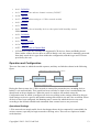
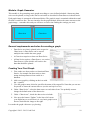
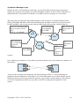
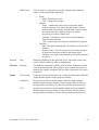
Operation and Configuration
There are four states in which the module operates, and they are linked as shown in the following
figure.
Optional: Retry configure/search missing devices
Start-up
Configuration
Running
Terminate
Optional: Configuration failed
During the Start-up state, the 1-Wire network is scanned for present devices, including devices
behind 1-wire network hubs. This search has been verified to a depth of two cascaded hubs, but
should work at deeper depths too. When the search is complete, the module enters the
Configuration state in which it configures all devices according to the settings defined by the user.
Such settings are device specific and includes settings like alarm levels and value resolution. When
all devices have been configured, the Running state is entered in which the devices are read
according to the defined schedule and commands from external sources are processed.
Operational Settings
1-Wire networks are mostly stable, but it does happen that a device temporarily is unavailable for
various reasons, especially on larger networks with long wires. There are two options to handle
such situations.
Copyright © 2012 - 2013 Code Zeal
13
•
Automatically search for missing devices every 15 minutes.
◦ With this option enabled, the module will enter a search-mode every 15 minutes when a
device is unavailable during start-up.
•
Instead of terminating when device configuration fails, retry every 15 minutes.
◦ With this option enabled, the module will resume normal operation even when the
configuration stage fails for a device during start-up.
Command Priority
Commands that are received from external sources, such as a component in a schematic, have
priority over the normal read schedule and as long as there are commands to process, the normal
read schedule is put on hold. In practical terms, this means that if too many commands are sent to
the module it will not be able to perform its normal procedure. A command does however not abort
a scheduled read already on progress when the command is received.
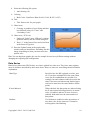
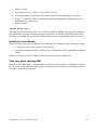
Setting up adapters and devices
Adding a 1-Wire network (adapter & devices) to
a configuration is done through the use of the
auto-search function. Simply press the button
labeled “Adapter scan”. When you do, the
application will search all available ports (Serial
and USB) for available adapters.
If a serial adapter is found, the application will
ask if it is of a DIY/Homebrew type in order to
handle it correctly
When the adapter search is complete, a question
asking if a search for adapters should be
performed is shown. Select Yes to search for all
connected devices on the found adapters.
Copyright © 2012 - 2013 Code Zeal
14
When device search completes, a view like that
to the right is shown with all devices listed on
the left side and the properties for the selected
device on the right side.
Each device type has its own set of properties, and there are a few common properties for all
devices:
• Enabled – if unchecked, the device will not be considered for any operation.
• Device information
◦ Label – specifies the name to use throughout the application when identifying the
device. Also used as database table name.
◦ Comment – allows for storing an arbitrary text along with the device, such as its
location.
• Scheduled reading
◦ Schedule – specifies the read interval for the device. This setting uses the Cron format.
◦ Enabled timed reads – if unchecked, the device will never be read according to the
schedule, only on direct request from an external source.
◦ Allow read values to be stored – if checked, a properly configured DB Storage module
will store the read values from this device. This only applies to scheduled reads, devices
read in other fashions do not result in values being stored.
◦ Distribute at tags – if checked, all read values for the device will be distributed as Tags
whenever a new value is read.
Adapters and multiple module instances
An adapter can only be used by one module instance at a time, so if you add two or more instances
of this module, you must disable all adapters except those you intend to use in the current module
instance. When the adapter is disabled, the devices on that adapter are hidden in the network tree.
Copyright © 2012 - 2013 Code Zeal
15
Module: Database Storage
This module has only one purpose; to store data gathered/published by other modules in a database.
It requires only a configured database connection to be operational. Once activated, the module will
translate messages sent from other modules into tables and columns in the database. Only one
database connection can be selected, but you may add additional instances of the module to store
the data into multiple databases.
It can operation in two modes:
•
Processing all general storage requests from other modules
•
Processing only those requests that specify a specific database connection.
The latter mode is used together
with a DB Writer component
configured with a specific
database connection. The reason
for the second mode is to allow
for configurations where the DB
Writer component decides where
a value should be written and not
the Database Storage module.
The second mode has one
limitation that it is important to
be aware of; it does not function
between different instances of
BM linked together with a
Network Binder module, even if the database connections are configured with the same name. Also
see “Storing tags” below for additional ways of storing values from a schematic and/or modules.
Regardless of operational mode, all connections used by the module are kept alive for the
configured time. By setting this to a time slightly longer than the shortest interval between two
write requests it is possible to keep the number of reconnects to the database server to a minimum,
thereby improving performance.
Storing tags
As your system grows and you come to see the possibilities, you will find that the default
functionality for storing values are not meeting your demands. For example, most modules can
publish values on a per-device/unit basis for direct storage, but what if you want to combine
multiple values into from different sources? This is where the Tag Groups tab comes into play.
By adding one or more groups, you can define a set of tags that shall be stored in a single table, as
specified in the group. For each tag, you can specify the column name and data type it should be
interpreted as but in most cases you can leave it as “Auto” unless you know the value to be outside
the limits of what can be parsed as a boolean, double or date/time type. If a boolean tag is selected,
the type selection becomes unavailable.
There are a few rules that determine when a group is written to the database:
•
All tags within the group must have been updated at least once.
•
The write policy must be fulfilled
Copyright © 2012 - 2013 Code Zeal
16
◦ All updated – when selected, nothing is written until all tags within the group are
updated with a value since the last time the group was written. This means that some
values may be updated multiple times between each write while others are only updated
once.
◦ Any updated – when selected, the group is written any time a value is updated. Note that
an update with the same values as the previous update also counts as an update – there is
not filtering.
◦ Flank of boolean tag – when selected, the value of the selected boolean tag in
conjunction with the selected flank (positive [false to true], negative [true to false] or
both) [any change] determines when the group should be written. This can be used to
either send a “write command” from a schematic or to initiate a write based on a tag
published by another module.
•
The tag being parsed is not a refresh broadcast, i.e. the tag is not sent as a refresh from the
Tag Storage module in response to a refresh command. In other words, only tags that has
actually been updated are taken into consideration.
Copyright © 2012 - 2013 Code Zeal
17
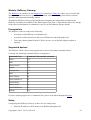
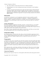
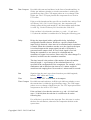
Module: Graph Generator
This module is for generating static graphs according to a user defined schedule. Almost any data
series can be plotted; as long as the data is retrievable as described in Data Sources it should work.
Each graph image is structured as illustrated below. The graph in turn is contained within the actual
file that is written to disc. The user interface for the graph module follows the same structure as the
graph image – remember this and you will have an easier time finding the settings you need.
Graph
Chart Area
Chart Area
General requirements and rules for creating a graph
•
Data Series are what is plotted in the respective
Chart Areas. A Data Series can be reused
multiple times within the same graph.
•
A Chart Area requires at least one Data Series.
•
A Data Series requires a Data Source, see section
Data Sources, from which it will retrieve the
data that should be plotted.
Creating Your First Graph
1. First, make sure that you have a functional Data
Source, for example one that retrieves time
stamp and temperatures from a table in a
database.
2. Add a new graph by clicking on the icon with
the +-symbol.
3. Give the graph a name, this also specifies the name of the output file. Note that you can use
'keywords' to insert the current time etc (see the tool tip for a list).
4. Under “Data Series”, select the data source to read values from. You probably want to
change the default name of the data series.
5. Under “Chart Areas”, check the data series to include.
6. Now press the button “Update” in the lower left corner
(you might have to scroll down). A very basic graph is now
shown, much like the image to the right.
Lets make the graph a bit more eye-pleasing.
Copyright © 2012 - 2013 Code Zeal
18
8. Select the following file option:
1. Anti Aliasing: All
9. Coloring
1. Back Color: Cornflower Blue (R:100, G:149, B:247, A:255)
10. Title
1. Title: Enter a title for your graph.
11. Chart Areas
1. Coloring: A gradient of your liking and then
two different colors for “Color” and
“Secondary Color”
12. Chart Areas / X/Y Axis
1. Under tab “Label” enter “HH:mm” (without
quotation marks) into the format string box.
2. Enter “1” in the Interval box and select Hour
in the Interval Type box.
13. Press the Update button in the graph render
window and you should have something like this
image, depending on what your data and color
options were.
Hint: You can duplicate graphs, this can for example be used to try different settings without
changing the original graph configuration.
Data Series
Data Series (abbreviated 'DS' below) are what is plotted in a chart area. They have many options,
most of which are described by their name alone. However, there are some things that need further
explanation.
Chart Type
Specifies how the DS is plotted; as a line, area
etc. If you have multiple DS in the same Chart
Area, not all combinations are possible. For
example, bar and columns cannot be used in the
same Chart Area and when using Stacked types
each series must have the same number of data
points.
X-Axis/Indexed
When checked, the data points are indexed along
the X-axis instead of being placed by its actual
value. If enabled, and two or more series are
enabled, both must have the same number of
data points.
Gradient
If a Gradient is enabled, it takes precedence of
any other color for the same area. Cannot be
used together with Hatching.
Copyright © 2012 - 2013 Code Zeal
19
Hatch
The hatch color is taken from the color for the
same area. Cannot be used together with
Gradient.
Keywords in Legend Texts
Each data series has the property “Legend Text” where you may enter a text that will be displayed
in the legend for each chart area. By using certain keywords, you can extract values and calculate
certain mathematical expressions. The allowed keywords are:
#TOTAL
Total of all Y values in the series.
#AVG
Average of all Y values in the series.
#MIN
Minimum data point of all Y values in the series.
#MAX
Maximum data point of all Y values in the series.
#FIRST
First data point of all Y values in the series.
#LAST
Last data point of all Y values in the series.
All keywords allows the usage of format strings. Format strings are appended to the keyword and
always begins and ends with an opening and closing brace: #KEYWORD{#.##}
There are several format strings available, you can read the full specification here and here, but for
most use cases a combination of the #, 0 and .-character will be sufficient.
Examples
#AVG{#.##}
Round the average value to two decimals
#LAST{00.00}
Display the value using at least two digits
#FIRST{#}
Round the value, no decimals
Look here for more examples.
Custom Titles
Under tab Chart Appearance/Custom Titles, you can add your own title boxes and place them where
you want on the graph.
Keywords and macros in custom titles
The custom titles supports several keywords and macros that results in auto-replacement with actual
values.
Keywords
{DATE}
Copyright © 2012 - 2013 Code Zeal
Returns the current local date.
20
{TIME}
Returns the current local time.
{UTCDATE}
Returns the current UTC date
{UTCTIME}
Returns the current UTC time.
{yy}
Year, two digits
{yyyy}
Year, four digits
{MM}
Month, two digits
{dd}
Day, two digits
{hh}
Hour, 12h format
{HH}
Hour, 24h format
{mm}
Minute, two digits
{ss}
Seconds, two digits
{PATH}
Returns the path, excluding the file name to
where the graph is stored.
{FULLPATH}
Returns the path, including the file name to
where the graph is stored.
{NAME}
Returns the name of the graph, as specified in
the graph configuration.
{HEIGHT}
Returns the configured height of the graph.
{WIDTH}
Returns the configured width of the graph.
Macros
%MEAN( 'source' )
Returns the mean value of the Y-values for the
given data source.
%MEDIAN( 'source' )
Returns the median value of the Y-values for the
given data source.
%LASTVALUE( 'source' )
Returns the last value of the Y-values for the
given data source.
%MAX( 'source' )
Returns the maximum value of the Y-values for
the given data source.
%MIN( 'source' )
Returns the minimum value of the Y-values for
the given data source.
Copyright © 2012 - 2013 Code Zeal
21
Example:
%MEAN( 'outside, west' )
results in the mean value of the data source which has its Name-element set to “outside, west”
Note:
Values returned by these macros are always retrieved from the Y-axis of the data source.
The single quotation marks must be included in the configuration, thus is %MACRO('source') valid
syntax, %MACRO(source) is invalid.
Hint: By inserting “\n”, you can force a line break in the text.
Copyright © 2012 - 2013 Code Zeal
22
Module: Mail Gateway
Please note: To utilize this module, you also need the Rule Engine or the User Module Engine.
E-mail is great thing and with today's
smart phones and tablets it can be used in
many ways, such as for notification and/or
controlling units connected to your
system. The purpose of this module is to
act as a gateway to one or more e-mail
accounts, allowing e-mail to be both sent
and received from within BM.
A Word of Caution
We recommended against using your
regular e-mail account for the purpose of this module. Instead, setup a separate account dedicated
for use with this module.
Configuration
Authentication
All serious e-mail providers requires the e-mail client to authenticate before being allowed to send
e-mails in order to prevent their systems from being used by anonymous spammers. This module
supports two modes of authentication:
•
Normal authentication using user name and password.
•
Pre-authentication using POP3. When enabled, the module will first log in to the POP3
server using the provided account details before attempting to send an e-mail using SMTP.
Although the module allows both to be be activated at the same time, one should be sufficient. Ask
your ISP which one that applies to you.
Port Numbers
The standard SMTP port number is 25, but most ISP/e-mail providers blocks this port and tend to to
configure their SMTP servers to use another port, often 2525, instead.
The standard port for POP3 is 110. When using a secure POP3 connection (by checking the
appropriate check box) the port should usually be changed to 995, but this may vary so check with
your ISP/e-mail provider.
Retrieving Mail
As each mail is received from the server, it is transformed into a format that can be distributed
internally between modules. Note that attachments are not supported at this time.
You may configure each separate account to for manual (instead triggered though a rule schema) or
automatic, periodic, retrieval of e-mails in 1 minute intervals. Entering a 0 will disable the
automatic retrieval. To filter which messages that shall be retrieved and parsed, you may enter a
Copyright © 2012 - 2013 Code Zeal
23
filter string that must be present anywhere in the subject of the e-mail (case insensitive comparison).
Note: If you choose not to delete the email after retrieval, the same messages will be read over and
over until you manually delete them.
Configuration Example
Google Mail
Google provides all the required information to configure BM to work with GMail on this page but
in short, the following settings have been seen to work:
Outgoing:
•
SMTP Server: smtp.gmail.com
•
Port: 587
•
Pre-authenticate using POP3: No
•
Login using credentials: Yes
•
Enable SSL: Yes
Incoming:
•
POP3 Server: pop.gmail.com
•
Port: 995
•
Enable SSL: Yes
Copyright © 2012 - 2013 Code Zeal
24
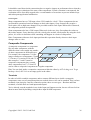
Module: Network Binder
Sometimes, it is desired to connect two or more instances of BM to build a larger system out of
smaller parts. For example, lets say you have a low-power computer (connected via WiFi) running
in your garage for monitoring of temperatures and light control and a media server in your main
building running a second instance for
additional monitoring and control.
Connecting the two instances would enable
you to use devices from either instance in a
schema as if they were part of the same
system.
This is where the Network Binder comes
into play. It enables you to connect a number
of instances together into a larger system,
the only requirement is an existing network
connection between the physical locations;
be it WiFi, hardwired, GPRS/3G or other
media.
It provides to operational parts:
•
Server - other instances of the Network Binder can connect to it.
•
Client - the Network Binder connects to a remote server instance.
Hint: This module provides a great benefit when designing schematics in Sanity to be run in the
Rule Engine module, as Sanity can connect and receive live data from the server giving you live
feedback directly in the editor.
Message Distribution
All messages are distributed to all connected clients/servers, as well as internally in the local BM
instance with two restrictions:
•
Hops To Live (HTL). A 'Hop' is the transference of a message between client/server A and B
(illustrated as an arrow below). Each time a message hops from one to the other, the
messages' HTL-counter in decreased by one and when it reaches zero, the message will not
be distributed further.
•
A message is never sent back the way it came to prevent rouge messages in the system.
Copyright © 2012 - 2013 Code Zeal
25
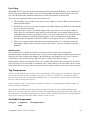
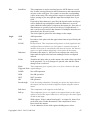
A problem: Message Loops
Despite the above two distribution restrictions, you can still end up with messages doing loops
within your system if you configure your Network Binder instances to form a circle connection, as
illustrated below. The problem is in that the server BM1 processes message A a second time.
This image does not show the full problem though, as the message A is actually distributed from
BM1 to both BM2 and BM3, which means that before the message is deleted, it is processed twice
by BM2 and BM3, and as many as three times by BM1 before the message is deleted from all
End: A is received by BM1
A is forwarded to
BM3 receives A
and processed a second
the originating
and processes it.
time.
server BM1
HTL:1
HTL: 0 – A is deleted
BM1
BM3
Start: Message
A is created and
processed.
HTL:3
BM2
BM2
receives A,
and
processes it.
HTL:2
A is sent to
server BM2
A is
forwared to
BM3
systems.
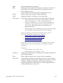
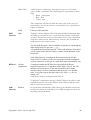
Even with only two instances, it is possible to get this problem if you cross-connect two instances of
this module:
Server
Server
Client
Client
To prevent this situation from happening, the default setting for HTL is 1, thus eliminating the
problem in most installations as a message is never forwarded when received from another system.
Should you need to connect more than two systems, you can either connect them in a star network,
or in series. Depending on which one you choose, the HTL-setting must be updated for each
system.
Copyright © 2012 - 2013 Code Zeal
26
BM2
BM1
BM3
BM3
BM4
Star network. BM2, 3 & 4 requires HTL: 2, BM requires HTL:1
BM1
BM2
BM3
BM4
Series network. BM1 & 4 requires HTL: 3, BM2 & 3 requires HTL:2
Connecting With BM Tool
To which Network Binder instance should BM Tool connect, and what HTL setting should be used
in the above two scenarios?
Remember that the transfer to the tool adds one Hop. This gives the following answers:
•
Star network: Connect to BM1 and set HTL in Sanity to 2.
•
Series network: Connect to either BM2 or BM3. Set HTL in Sanity to 3.
Copyright © 2012 - 2013 Code Zeal
27
Module: RFXtrx Gateway
This module adds support for RFXCOM's USB RFXtrx433 transceiver. With it, you can both
control (through the Rule Engine module) and gather data from devices that are compatible with the
device, such as NEXA's lightning devices and also temperature/humidity sensors for various
weather stations. Controlling certain projector screens are also possible.
Configuration
When plugged into your computer, the RFXtrx device will show up as a serial port through which
BM will communicate with the device. Simply select the port where the device is located and save
the configuration to enable the module. The device supports a long range of devices, using many
different communication protocols. Each protocol to be used (for receiving) must be enabled before
the device will listen for devices using the respective protocol. The rule is that only those protocols
actually being used should be enabled; this will increase the sensitivity of the device. Some
protocols cannot be used together, please refer to the RFXtrx Users Guide for more information.
The test button lets you test the communication with the device, observe the output in the text box
above the button. If communication is established, a window will show the last received data packet
until you close it. Note that you cannot use this test function while the module is active as the port
will be busy.
Data logging
The module is capable of
distributing both sent and
received data for storage in a
database through the use of
the Database Storage module.
Which devices to log data
from is determined on the tab
“Devices”. The list of devices
is populated on-the-fly as data
Copyright © 2012 - 2013 Code Zeal
28
is received from the module though the Network Binder module, so for this to work, you must be
connected to the NB-module.
Specifying a custom label for a device is optional, but recommended as the default label is just a
copy of the unit id. Also note that the label will become the name of the table in the database. The
two options “Outgoing” and “Incoming” refers to data going out of the device, i.e. being sent, and
data going into the device, i.e. being received from an outside source. The actual data being logged
depends what is available for the specific device family.
Copyright © 2012 - 2013 Code Zeal
29
Module: RaZberry Gateway
The RaZberry, an extension to the Raspberry Pi created by Z-Wave.me, allows you to control and
react upon events from devices on a Z-Wave network, such as wall plugs, door sensors, motion
detectors and temperature/humidity sensors.
Through the RaZberry Gateway, Beyond Measure integrates the information provided by the
RaZberry and makes it available for the Rule Engine in the form of Tags and also allows for storage
of the retrieved information in a database by the use of the Database Storage module.
Prerequisites
The RaZberry Gateway requires the following:
•
A properly setup RaZberry on a Raspberry Pi.
•
A network connection between the server BM runs on and the Raspberry Pi.
•
To do more than log data from the Z-Wave devices, use of the Rule Engine module is
required.
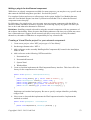
Supported devices
The different Z-Wave devices may support one or more of the many command classes.
Currently, the following command classes are supported.
Command Class
Command Class number (decimal)
Alarm
156
Basic
32
Binary Switch
37
Battery
128
Configuration
112
Meter
50
Sensor Binary
48
Sensor Multilevel
49
Switch Binary
37
Binary sensor
48
Switch Multilevel
38
Wakeup
132
If you are missing support for a Command Class, please let us know through the forum.
Setup
Configuring the RaZberry Gateway is done in a few simple steps.
1. Enter the IP address or DNS name of the RaZberry/Raspberry Pi.
Copyright © 2012 - 2013 Code Zeal
30
2. Enter the port number the RaZberry service is
listening on.
3. Choose an Update Interval. This setting
determines how often the RaZberry is asked for
updated information since the last update.
4. Enter a network name. This is used to identify
this particular network if multiple RaZberry
devices are used. See also the RaZberry
Gateway components in the Rule Engine.
5. Choose how many parts of the alias that are to be used to build a table name when a value is
logged to database. See below for more info on this.
Device aliases
When working with the device aliases, you need to be connected to the BM service, otherwise some
parts of the interface are disabled.
By deault, values are published as Tags using the name format “network
name::deviceno::instance.no::commandClass(Name)::subpart::value”. While these are perfectly fine
to use, they are not very readable. Instead, you can create aliases for each value you want to use.
You can enter the tag name manually, or selecting one of the available from the menu presented
when you click the “...”-button. To determine which Tag that corresponds to which device, please
refer to the RaZberry Expert UI. Please note that only Tags beginning with the network name set in
the configuration for this module are displayed.
The entered alias will also be used as the table name when the “Log to database” option is selected.
Using the setting “Use n parts for DB table name”, a table name is built of the n last namespace
parts. In the example above, the name would be “TV_kWh”. In case there is only one part in the
alias (i.e. no “::”) or too few, as many parts as are available will be used.
The button “Request update of units” will send a command to all active RaZberry modules,
requesting that they perform a full refresh of available devices from the RaZberry.
Note: When an alias is created, the default tag will no longer be updated.
Controlling devices
Devices whose values are published can also be controlled, simply by setting the Tag to the desired
value from withing a schematic using the tag components, or through the use of the Tag Storage
interface.
Copyright © 2012 - 2013 Code Zeal
31
Adjusting configuration options for a device through BM.
Please note that adjusting configuration values may result in not-functioning devices, use caution.
Configuration values are also reported to BM as tags, therefore you can adjust them (if they are not
read-only, see the device's manual) by setting the Tag to a new value.
Example:
Tag: RaZberry::D13::I0::C112(Configuration)::Parameter::39::Value
Value: 600,2
In this case, the value is “600”, and the size of the value, in bytes, is 2. When adjusting the value
you look at what is published by the device and then adjust the first part of the value as the second
part should be the same as was published. For example, if e wanted to decrease the value to 500, we
would send “500,2”.
Please refer to the manual for your device for information on what each configuration setting is
used for and what the valid values are.
Copyright © 2012 - 2013 Code Zeal
32
Module: Rule Engine
In 1854, George Boole developed what is known as Boolean
algebra. Today you take advantage of his work almost
without noticing it – any electronic device with a
microprocessor (such as a personal computer, smart-phone or
calculator) uses Boolean algebra to perform its tasks. Now
you actively can take advantage of his work through the use
of the Rule Engine module.
This module really embodies what BM stands for - flexibility
and the user's own choice. It brings together different worlds,
such as 1-Wire, xAP and SMS into a single domain where the user can make them interact in a way
he or she wants.
It should be noted that, while some of the components included with this module functions without
external dependencies, many requires other modules to be activated and configured.
The Basics
This module do not perform any operations on its own, instead it loads a set of user-built schematics
that define the operations to be performed based on input from internal or external sources. Of
course, it is entirely possible to write a schematic that is fully self-sustained if the requirements are
such. Adding and removing schematics to load is done via the module configuration, as for any
other module.
The Play and Pause buttons sends a
message to a running instance of the
Rule Engine module (via Network
Binder) to unload or load the specified
schematics. This only works if it is
known to the module in the currently
running configuration. The Edit button
naturally opens the schematics in an
editor.
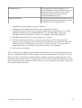
A First Example
Lets say that we have a 1-Wire network switch (DS2406) connected to a push button on the front
door, and when someone presses that button we want to have our computer say the phrase “There is
someone at the front door”.
A schematic that realizes this functionality can look what is illustrated in this image.
Copyright © 2012 - 2013 Code Zeal
33
In short, it functions as follows:
1. The 1-Wire module reads the status from the device labeled 'FrontDoor'.
2. The Rule Engine receives the resulting status message and forwards it to the FrontDoor
component.
3. If activity was detected on the input of the switch, the output ActivityA will go high and a
clock pulse emitted on the CLK output. Together, they the are AND:ed (C1) into a clock
pulse for the TTS component, Sound1, which will send a command to the Sound module to
output the phase read from the component's Text input; the String component (D1) holds the
phrase to speak.
Schematics
As seen above, a schematic is a set of components connected via wires to perform a specific
function. A schematic is in itself a special type of component – a Composite Component, see
chapter Composite Components, but labeled as a 'schematic' since it is the topmost/encompassing
component. You use the schematics editor (accessed via menu Tools/Rule Editor) to create your
schematics.
Custom Components
By saving a Composite Component to the folder <data-dir>\ComponentLibrary, you can make
your own components available for reuse from the library. If you want to organize your own
components into separate sections in the library, simply create sub folders in the ComponentLibrary
folder, and they will be shown parallel to the Custom-section.
Note: When a custom component has been added or removed from a the library, you must reload
the library through the menu Library/Reload from the editor's menu.
Component Library
The component library, on the left side of the editor, is where all available components are held.
These are added using drag-and-drop into an editor. The components are sorted by their type, such
as Logic (AND, OR), Terminals, module-specific etc and can be mixed as you see fit in a
schematics.
Components
A component can be seen as a box that, given some input, performs a specific operation and outputs
the result on its output pin(s) and/or as a message to an external part, such as another module. Some
components are self-sustained, i.e. they are not dependent on external parts, while other components
requires another component or module to perform some operation before performing its own
operation. To rename a component, just double-click on the component name and enter the new
name.
Most components have a clock-input, and often a clock output, pin. These pins are used to trigger
an operation, or to signal that new data is available on the outputs of the component as a result of
the physical device being read.
Component Properties
When open, the Component Properties, on the right side of the editor, shows the properties for the
Copyright © 2012 - 2013 Code Zeal
34
currently selected component. All components have a color, rotation and comment property. Most
components have additional properties that can be adjusted to fit the requirements.
Note: If you do not want to use the images in the components, simply delete the corresponding
file(s) in the <application data>\ComponentImageLibrary folder.
Input and Outputs
Most components have both inputs and outputs. Inputs are always located on the left side of the
component and outputs on the right side. In- and outputs (commonly known as connection points –
see Terminals) are used to pass signals between two components, via a wire. There are two kinds of
connection points:
1. Boolean – these are used to signal either true (high) or false (low) signals. These connection
points are visualized as a square.
2. Data – these are used to pass arbitrary data, such as a string or a temperature value. These
connection points are visualized as a circle.
Pull States
All unconnected Boolean inputs have a default pull-state (default value) of false, as indicated with
red coloring. By pressing and holding shift and right-clicking on an input, the pull-state is toggled
between true (colored green) and false. When a wire is connected, the pull-state does not have any
effect.
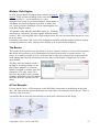
Signal Quality
Depending on how a schematic is built, there are times
when the state of the input/outputs are unknown. This is
known as a signal having bad quality. For example, look
at the schematic in the image (a user-built 3-input AND
gate). This schematic has three inputs, I1, I2 and I3 and
one output, O1. Since neither of the inputs has a
connected wire, they have neither a true nor a false value,
thus the quality is bad. Bad quality is visualized with a
black coloring of the connected wires.
When a component has an input with a bad signal quality,
the component will in most cases not operate until all inputs has a signal with good quality.
Circular Connections
When designing a schematic, one should take care not to create
circular connections. The image illustrates a non-functional SRFlipFlop circuit. The reason it is not functional is due to the
circular connections between components C1 and C2. As each
component is dependent on the others output, neither is able to
provide a good signal quality on its output. To solve this issue, a
pull-down or pull-up component can be inserted between C2/O1
and C1/I2.
The Pull down-component pulls its output low when it receives a
bad quality on its input pin, thus making it possible to connect as desired.
Copyright © 2012 - 2013 Code Zeal
35
It should be noted that circular connections have a negative impact on performance due to that they
cause a recursive evaluation of the state of the components. If such a situation is encountered, the
evaluation will be forcefully stopped after a certain number of recursions to prevent infinite loops
and subsequent application malfunction.
Clock Signals
Many components have a CLK-input, where CLK stands for “clock”. These components do not
perform their operations based on changes on their other inputs, if any. Instead, they require a
clock-pulse (low to high state change) to be provided on their clock input. When such is detected,
the component perform its operation.
Some components also has a CLK-output. When such is the case, they first update the values on
their other outputs, if any, then they provide a clock-pulse on their clock output. By using the clock
pulses, it is easier to determine when something will happen in a chain of components.
Hint: Components without a clock input perform their operation directly whenever their input
changes state or value.
Composite Components
A composite component is a component
like any other component, with the
difference that it can contain any number
of other components in different layers.
For example, the component C1 in the
image contains two components, C2 and
C3. In turn, C2 consists of C4 and C5. In
this example, C1 and C2 must be
composite components (they contain
other components) but C3, C4 and C5
can be either a composite component or a regular component.
Hint: You can look inside a composite component within the editor by ALT-clicking on it. To go
back up a level, ALT-click on an empty space in the editor.
Terminals
In order to build a reusable component, and to connect different layers inside a composite
component, some sort of connection points are needed where wires can be attached. This is where
terminals come into play. Just like connection points, there are two types – Boolean and Data
terminals, of which there are both inputs and outputs.
You've already seen the terminals in use in the Input and Outputs section, but we will now look at
them in more detail by building a simple three-input NAND component.
Copyright © 2012 - 2013 Code Zeal
36
First, we create a schematic with a three-input
AND circuit. The Boolean inputs (B/I) will serve as
the input connections when using the schematic as
a component. Likewise, the Boolean output (B/O)
will serve as the output connection.
After saving the component in the
ComponentLibrary (named 3AND), reload the
component library from the menu. and add it to a
new schematic and connect three input terminals
and a NOT-component and also a final output
terminal as illustrated in the image.
Again, save the schematic as a new component in
the ComponentLibrary (named 3NAND), reload
and add a copy of it to a new schematic. You have
now built a composite component in two layers. An
additional output terminal has been added in the
image, just to illustrate that the output of the
3NAND component in fact has a value of true.
Hint: By right-clicking on an input terminal, you can set a temporary value it should provide on its
output. This way, you can test a schematic directly within the editor.
All terminals have a Sort Order-property that is used to determine the order of the resulting pin of
the parent composite component. The sort algorithm works like this:
•
All Terminals with a sort order larger than 0 are sorted in ascending order and placed first
(top) on the resulting composite component. Input and outputs may have the same Sort
Order.
•
The rest of the components are sorted alphabetically and are placed after the others.
Wire breaks
Wire breaks can be used to route a wire in a more esthetic way around other components, but also to
split a wire in two. By pressing Ctrl-Shift while left-clicking on a wire, you add a wire break to it.
You can then move the break point to where you wish. Connecting other wires to it is done as
normal, but in order to pull a wire from it, you must press and hold shift, otherwise you'll move the
break point instead. You can easily 'unbend' a wire by pressing Ctrl-Shift while left-clicking on the
wire break (this only works if there are exactly two wire connected to it). Removing a wire break
will also remove any wires connected to it.
Copyright © 2012 - 2013 Code Zeal
37
Live View
When BM Tool is connected to the kernel using the Data Link/Network Binder, your schematic is
run directly from within the editor as if it was running under the Rule Engine module. This way,
you can edit and test the schematic and directly see the results based on actual data.
There are a few important items you need to be aware of:
1. The schematic is run as the current user so access rights etc. may be different than when run
under the Rule Engine.
2. If BM Tool is not run on the same computer as the Rule Engine any differences between the
two may affect the outcome.
3. If the schematic is active in the Rule Engine at the same time as it is run from within an
editor, there is a risk that they may interfere with each other. For example, double sets of
commands may be sent to an external system – one from each instance. To avoid this, either
unload the schematic in the Rule Engine module, or prevent outgoing messages from
leaving Sanity through the Link/Data Link/Block all outgoing non-user commands menu.
4. There is no synchronization made between a running instance of a schematics under the
Rule Engine and the same schematics opened in an editor – they are completely separate
instances.
Oscilloscope
The oscilloscope (accessible via Tools/Oscilloscope) can be a great aid in viewing and
troubleshooting a schematic. You add (right-click) a probe to either input or output connections and
whenever the value on that point changes, the oscilloscope will display the new value. A probe is
removed by pressing and holding CTRL and right-clicking on the input or output.
Boolean data is always presented as either 0 or 1, while a data point will be presented as its actual
value, but only if it is convertible to a numeric value. Values that are not convertible can be viewed
in the ‘Data’ tab, where all values are presented in text format, with the most recent value at the top.
Tag Components
A Tag is a user-defined pair of a name and a certain value. Using a tag, you can abstract a physical
device into a logical one. For example, if you use a 1-Wire or xAP device to monitor the state of
your front door, you can distribute the resulting value as a Tag, thereby removing the need to know
how the value is read by the system.
Tags can also be used to create your own named “signals” for communication inside a single, or
between multiple schematics.
Note that tags of different types do not interact with each other. So you can have multiple tags
named “A” as long as they are of different types. Having multiple output tags of the same type with
the same name is strongly discouraged as it usually creates unwanted side effects. Having multiple
inputs of the same type and same name is however not an issue.
Available Components
Category
Component
name
Description/Notes
Copyright © 2012 - 2013 Code Zeal
38
1-Wire
These components represents a physical device on a 1-Wire network, and requires its
physical device to exist to function. Each component is named by its official name. To
pair the schematics component with the physical device, rename the component in the
schematic to match the label or ROM code of the device in your configuration.
All 1-Wire components have a pin named ReadCLK used to request a read of the
device. One example usage is to control the read schedule via a schema instead of
from the 1-Wire module's schedule configuration. All 1-Wire switches have a
WriteLatchCLK input to trigger a write-command to the latches.
DS1822
DS18B20
DS18S20
DS2405
DS2406-1
Single channel version of DS2406
DS2406-2
Dual channel version of DS2406
DS2408
DS2413
DS2423
DS2438
DS2438
Humidity
When you configureyour DS2438 as a humidity device, you can use
this component to use the humidity values in a schematic.
DS2450
DS2760/61/62
LCDHobbyboa
rds
Data
LCDSwart
Due to a limitation in the firmware of the device, it does not support
reading latch states on the outputs and thus does not support the
synchronization procedure used with with other switch-devices.
Compare
Compares the input values according to the specified operation. If
both values can be converted to a number then numerical comparison
is used, otherwise culture invariant string comparison used used.
Counter
Increases/decreases a counter in the direction and step specified for
each clock pulse. Emits a clock pulse after each change.
Data select
Selects between two input values based on the Select-value. Low,
selects value at input D1.
Hysteresis
This component applies a hysteresis on a (numerical) input value.
The reference value is read from the 'Reference' input, the hysteresis
value from the 'Hysteresis' input and the value to apply hysteresis to
from the 'Value' input. Example: With a reference value of 5 and
hysteresis of 3, the output pin (and clock) will change on the values 2
and 8.
Copyright © 2012 - 2013 Code Zeal
39
Math
Performs mathematical operations.
Shift
Shift register. Data is taken from input I1, to output O1, then O2 on
each clock pulse. Enable determines if the component is active.
Reset clears the outputs.
Can be chained to create shift registers holding more values.
String
Holds a single string as input to other components.
Strlen
Outputs the number of characters of the input string.
Text Format
Formats up to four strings/values into a single string at its output.
• The component has four inputs, D0 through D3. These are
known as argument 0, 1, 2 and 3 in the format string.
• The input “TryNumeric” is used to tell the component if it
should try to treat the input values as numerals instead of
plain strings. This option needs to be enabled to use
numerical formats.
• The Pad-inputs allows padding the result up to a fixed length
(PadLeft/Right) using a specified character (PadChar)
There are numerous format option available; please refer to
Microsoft's MSDN documentation for all details:
• Standard Date and Time Format Strings
• Custom Date and Time Format Strings
• Standard Numeric Format Strings
• Custom Numeric Format Strings
Specifying a specific culture format is not supported, the invariant
culture is always used, which basically corresponds to English
formatting.
Examples:
• First argument, one decimal: {0:0}
• Third argument, two decimals: {2:00}
Transform
Transforms the input value according to the specified transformation
and decimal properties.
Value
Hold a single numerical value as input to other components.
Value View
A kind of mini-oscilloscope, allowing an easy view of data within a
schematic. Whatever data value is available on the input, it is printed
inside the component. If the entire value cannot be fit into the
component, just hover with the mouse over the component and the
tool tip will display the entire value.
Copyright © 2012 - 2013 Code Zeal
40
XML Parser
Used to retrieve a value from a specific path/tag and/or attribute
within a well-formed XML data block.
•
•
•
Inputs
◦ XML- XML data to read
◦ CLK – triggers the parsing
Outputs
◦ Value – contains the value retrieved from the found
element. In those cases where the path results in an an
element with sub elements, the full XML structure from
the current element is made available for further
processing in an other XML Parser.
◦ Attribute - contains the value retrieved from attribute
from the found element.
◦ CLK – pulses when a new block of data has been parsed.
Properties
◦ Path – the path (including the root element) to the desired
element.
◦ Instance count – used to select one of the many instances
of the desired element (sorted by document order)
◦ Attribute – the name of the attribute on the found element
to retrieve.
Network
Ping
Sends an ICMP Ping to the specified server. The output reflects the
result, with the round-trip value in milliseconds.
External
External
The External component is differs from all other components in that
it can load external code, like a plug-in. Once loaded, that code can
interact like with the schematic like any other component. See below
for details.
Sound
Clear Sound
Clears the current and all enqueued sounds for the module which the
Target Module Instance Name property matches.
Sound File
Plays the specified file on the module which the Target Module
Instance Name property matches. If provided, the file provided on
the input takes precedence over the one specified in the properties.
TTS
Speaks the specified text on the module which the Target Module
Instance Name property matches. If provided, the file provided on
the input takes precedence over the one specified in the properties.
Copyright © 2012 - 2013 Code Zeal
41
Time
Date Compare
Provided with start and end dates, in the form of month and day, its
Within-pin indicates whether or not the current date is withing the
provided two dates. The CLK output pulses on every change of the
Within-pin. The UTC input pin tells the component to use local or
UTC times.
If the provided month and day specifies an invalid date, such as 29:th
of February 2011 (2011 is not a leap year), the component will
silently reduce the day and month in 1-day decrements until the date
is valid. E.g. 29:th of February 2011 becomes the 28:th 2011.
If the end date is less than the start date (e.g. end = 1/1 and start =
1/12) then the end date is considered to be during the following year.
Delay
Delays the input signal with a configurable delay, including a
configurable random element. Whenever a positive flank on the
input clock is detected, a time interval is calculated and a countdown
is started. When the countdown reaches zero, the signal on the input
is read and output on the output signal pin and a clock pulse is
generated on the output clock. If a new clock signal is received
during the countdown, a new interval is calculated and the
countdown is begun a new unless “Reset only if in-value changed” is
checked, in which case the countdown continues.
The time interval is the product of the number of intervals and the
interval length +/- a percentage of the calculated interval, as
specified in the configuration of the component. For example, a 50%
randomness and an absolute time interval of 1 minute results in
actual intervals ranging from 30 seconds to 1 minute and 30 seconds.
Sun
Signals when the sun is up or down based on provided longitude,
latitude, UTC offset and Zenith.
Time
Provides either UTC or local time on its outputs.
Time Compare Provided start and end times, itsWithin-pin indicates whether or not
the current time is within the provided time range. The CLK output
pulses on every change of theWithin-pin. The UTC input pin tells the
component to use local or UTC times.
If the end time is less than the start time (e.g. end = 01:00:00 and
start = 22:00:00) then the end time is considered to be on the
following day.
If a valid time is provided on the input pin Time, this time is used as
the base for calculations, otherwise the component defaults to the
system time.
Copyright © 2012 - 2013 Code Zeal
42
Time Delay
Adds or subtracts a random time interval from the date/time provided
on the BaseTime input, whenever a clock signal is received in the
input clock. The resulting date/time is provided on the Time output.
Copyright © 2012 - 2013 Code Zeal
43
Time Line
Allows the user to specify multiple events that sets a boolean and/or
data value on the components outputs based on the following
criteria:
• Time of day
• Week day
• Up to five optional inputs.
Time Line automatically uses the system time. A user defined time
can be supplied on the Time input pin.
The value specified in the Data value field of the configuration will
be output on D1 for the active event.
Binary outputs B1-B5 can be individually set to hi/low for each
event.
At least two events must be defined for the component to work.
The specified events are evaluated in time-ascending order and only
the last event found matching the criteria is allowed to set the
outputs. If no matching event is found, a backwards search is made,
one minute at a time, until at total of 24h has been subtracted from
the current time or a match is found.
If checked, the check boxes I1-I5 specifies that the corresponding
input(s) must be high for the event to be evaluated at all. This allows
for easy enabling and disabling of events based on other data
sources.
Fallback value
These check boxes and data value are are used as the output value
during the following specific event:
• An event is active (time an input states fulfilled)
• One or more inputs changes so that the input states no longer
are fulfilled.
During set up, you will need to sort the items if you change the times
of the events to get correct evaluation.
A typical usage case for this component is to turn on or off a device
(light, fan etc.) through the RFXtrx Gateway at specific times.
Clock outputs
The CLK-output pulses whenever one of the outputs changes states.
The EventCLK pulses whenever the active event changes.
Copyright © 2012 - 2013 Code Zeal
44
Database
DBReader
Using a special type of data source (see Data Sources), this
component reads the first row in the resulting data set and outputs
the values onto the O1 and O2 pins (if enabled in the source), and
then pulses the CLK out pin. If the operation succeeds, the Result pin
will be high during the clock pulse, otherwise low. Note that due to
the possibly memory- and time-consuming nature of the database
read operation, once a read request has been triggered by a positive
flank on the CLK input, no further read operations will be initiated
until the first one has completed.
DBWriter
This component is used to write a value to a database table. It
requires a Database Storage module, with a matching configuration.
There are two operational modes:
•
By selecting the “Specific database connection“, you can
specify a specific database connection to use when the value
should be stored.
•
By not selecting a database connection, any DB Storage
module (not configured for the above mode) that receives the
write request will process the message.
The expected columns in the table are:
•
index (64 bit integer, auto incrementing)
•
Timestamp (DateTime)
•
One column as specified in the component properties.
If the database and/or table doesn’t already exist, it will be created by
the DB storage module (assuming sufficient access rights).
The Result pin will indicate the result of the write request:
•
As reported by the DB Storage module when an attempt to
write the provided data has been made
•
As a result of the preparation of the request (value
conversions etc.), in which case only failures can be
reflected. (success can only be reported by the DB Module,
see (1) )
The out clock is pulsed every time the Result pin can be read. Please
note that, depending on your configuration (such as multiple active
DB Storage modules) you may get multiple pulses with different
result indications for each write request.
File I/O
File Monitor
Can monitor a file, or files, including sub directories, for changes
and output the path and file name when a change is detected.
Copyright © 2012 - 2013 Code Zeal
45
File Reader
Using regular expressions it can read a file one line at a time and
output up to four groups of data extracted from that line. Learning to
use regular expressions isn't something that is done in a few minutes,
but there are some resources available on the web. Once such is “The
30 minute Regex tutorial” by Jim Hollenhorst. Although a bit dated,
it is still very much a valid source of information. The tool used in
the article, Expresso, is at the time of writing free to use and register.
It is this tool, that I, the author of BM, recommend. Expressions
created in Expresso can be used directly in BM.
•
The component keeps a track file on disk that allows it to
continue where it left off last.
•
As the reader keeps track of the last read position by using a
tracker file paired with the file to be read, you should not use
multiple readers for the same file as doing so will cause the
readers to access the same tracker file and thus overwriting
each others read positions.
•
When it goes high, the CLK input triggers a new read cycle
of the file specified with the Path and Filename inputs.
•
If high during the clock pulse, the Reset input will reset the
read position to the beginning of the file. If this pin is held
constantly high, the file will be read from the beginning on
each clock pulse.
•
The “Require new line character” property specifies if the
line must end in a new line before being parsed.
Example
The regular expression, without quotes,
“(?<g1>.{1,})\:(?<g2>.{1,})\:(?<g3>.{1,})\:(?<g4>.{1,})\;”
would match the line, without quotes, “a:b:c:d;”
If g1, g2, g3, g4 had been entered in the component properties for
Group 1-4, the values “a”, “b”, “c” and “d” would have been made
available on the outputs.
TextOut
Can write data to a file.
Copyright © 2012 - 2013 Code Zeal
46
I/O
SerialPort
This component is used to send and receive ASCII-data on a serial
line. It takes a string (limited to ASCII-characters) and outputs them
as bytes on the serial port. Use \n and \r to insert the corresponding
values in the string. The string will be stripped of actual line breaks
before parsing so you may split the input onto multiple lines if you
wish.
If an end-of-data character is specified, the input from the serial port
will be buffered (up to 4096bytes) until the character is received
upon which the entire buffer is output on the output pin. If no end-ofdata character is specified, each received byte is output directly. \r
and \r can be used as end-of-data character. If multiple characters are
entered only the first one is used.
The clock signal is pulsed for each change on the output.
Logic
AND
AND operation.
CLK
Provides a clock pulse with the approximate interval specified by the
properties.
D.CLK
Delayed clock. This component will generate a clock signal after the
configured interval whenever a clock pulse is sensed in its input. If
another clock pulse is sensed before the interval expires, the interval
starts over again without triggering a clock pulse on the output.
Debounce
Debounces the input, i.e. does not set its output to the value of its
input until the input value has been unchanged for the configured
interval.
D.Out
Transfers the input value to to the output value with a delay specified
in the properties. Up to 50 changes are queued, after that the oldest
change event is removed.
Flank
This component gives a pulse (false-true-false) whenever the input
Triggered Pulse signal changes.
NAND
Not AND operation.
NOR
Not OR operation.
NOT
NOT operation.
OR
OR operation.
Pass through
Used for testing schematics. Normally just passes the input value to
the output, but may be locked to high/low output using the context
menu.
Pull down
This component is the opposite to the Pull-up.
Pull up
This component give a true signal on its output whenever the signal
quality is bad on the input. Otherwise it will just give the same signal
as that on the input.
Shift
Shift register. Value is taken from input I1, to output O1, then O2 on
each clock pulse. Enable determines if the component is active.
Reset clears the outputs.
Can be chained to create shift registers holding more values.
Copyright © 2012 - 2013 Code Zeal
47
Value View
A kind of mini-oscilloscope, allowing an easy view of boolean
values within a schematic. The input signals is represented by three
flags:
• Black – bad quality
• Red – false
• Greed – true
This component will always show the same color as the wire it is
connected to, but may be easier to view than the wire, especially on
higher resolutions.
Mail
Gateway
XOR
Exclusive OR operation.
Mail
Together with the Module: Mail Gateway, the Mail component adds
the ability to send and receive e-mail from any number of different
accounts. You need to set the account name to use in the component
properties, otherwise the Mail Gateway won’t be able to match the
send-request to an e-mail account.
You can send the same e-mail to multiple recipients by separating the
input string on the To-pin with ‘;’, e.g
“[email protected];[email protected]”. Each send attempt will result in
a clock signal on the ResultCLK pin, with the result indicated on the
Result pin.
If the Mail Gateway is configured for manual retrieval, use the
RequestCLK to initiate a retrieval of messages from the configured
account, otherwise set this pin to a pull-down state (indicated by red)
RFXtrx/*
Various
components
Components under the RFXtrx tabs represents the different
supported end devices. Components with a high “Forced” pin will
attempt to keep the device in the state dictated by their inputs
whenever they receive a notification that the device is in another
state. Level-pins expects decimal values of 0-100%, i.e. 45.0 or
simply “45”.
Each device must be configured with their id.
“Lighting 4” components requires a Pulse Timing to be able to send
commands, please refer to the RFXtrx User Guide to find the value
that is correct for your device.
SMS
Gateway
Modem
In conjunction with Module: SMS Gateway the Modem component
provides the means to send and receive SMS messages and to act on
incoming call notifications.
Copyright © 2012 - 2013 Code Zeal
48
System
Execute
This component can start an an arbitrary process/application (.exe,
.bat etc.)
• Inputs
◦ The input clock triggers the execution when going from
low to high.
• Outputs
◦ ExecuteCLK – pulses when the configured command is
successfully executed.
◦ ErrCLK – pulses when execution fails for whatever
reason.
◦ ExitValue – if Wait for exit is selected, the exit value of
the process will be available on this port when ExitCLK
pulses.
◦ ExitCLK – pulses when the process has exited and Wait
for exit is selected.
◦ StdOut – contains the output of the process, if any.
◦ StdErr – contains the error output of the process, if any.
Note that, when Wait for exit is selected, a new process will not be
started until the previous one has exited. If Wait for exit is not
selected, the component will start a new process on each clock pulse,
which can lead to multiple running processes if care is not taken.
The standard output and standard error output of the process are also
logged as Info-messages in the Rule Engine log file.
Tag
BT/I
Boolean Tag Input – acts as an input for tags from the current or
another schematic.
The property Tag Name (case insensitive) specifies the name of the
tag the component should listen for and should match the name
specified in a tag output component. Press the “...”-button to display
all currently known boolean tags.
The output “Tag Name” mirrors the configured tag name (see above)
for use in the schematic.
“Validity time” determines how old a value may be before it is
considered invalid. When passed, the default value is provided on the
output, and the Expired output pulses once.
Any change on the outputs is followed by a clock pulse.
See Tag Storage for information about the concept of Tags.
Copyright © 2012 - 2013 Code Zeal
49
BT/O
Boolean Tag Output
The counterpart for the Boolean Tag Input.
The input “Tag Name” allows for dynamic update of the tag name.
The component will use the last updated name from either the
configuration or the input when a clock-pulse is detected on the
CLK-input. Please note that changing the tag name via the input pin
in the editor will also update the configured tag name.
The output “Tag Name” mirrors the currently active tag name.
ST/I
String Tag Input
Same as Boolean Tag Input, but for strings.
ST/O
String Tag Output
The counterpart for the String Tag Input
Tellstick
TS *
Components under the Tellstick tab represents the different
supported end devices. Components with a high “Forced” pin will
attempt to keep the device in the state dictated by their inputs
whenever they receive a notification that the device is in another
state. Level-pins expects decimal values of 0-100%, i.e. “45.0”, or
simply “45”.
Each device must be configured with their label, and in the case of
the TS Sensor, also the data type.
Components with the Result and ResultCLK pins signals the result
of commands on these pins.
Terminal
B/I
Boolean Input. Creates an input pin in a composite component.
B/O
Boolean Output. Creates an output pin in a composite component.
D/I
Data Input. Creates an input pin in a composite component.
D/O
Data Output. Creates an output pin in a composite component.
xAP
BSC stands for Basic Status and Control. Devices with the word
“mirror” in the name mirrors the state of a physical device (such as a
Netiom) and can also control it. The rest of the devices lives inside
the schematic, but are also visible on the xAP network. Read more
about xAP here.
BSC Level
Input Mirror
BSC Level
Output
BSC Level
Output Mirror
BSC State
Input Mirror
BSC State
Output
Copyright © 2012 - 2013 Code Zeal
50
BSC State
Output Mirror
XAP Reader
This device is capable of reading any xAP schema and retrieving one
value for each output pin from a block/key pair. For example, take
the following xAP message.
xap-header
{
v=12
hop=1
uid=FF400100
class=Weather.Report
source=mi4.weather.1
}
Weather.Report
{
tempf=19.2
utc=21:59:52
tempc=-7.1
icon=Dry
date=20110214
}
By configuring the component with the addresses and uid, it is
possible to retrieve the values from the key/value pairs within the
Weather.Report block simply by entering the block and keys into the
component properties.
XBMC
XAP Writer
This component is the opposite of the reader. By specifying block
names and keys, an xAp message is built with the data retrieved from
the inputs. You can specify the same block multiple times to add
more than key to the same block.
XBMC Player
Controls and reacts to events received through an XBMC Bridge
module with the same Instance name as configured for the
component.
The Video, Audio and Picture outputs indicates which type of player
that is active, if any.
The Connected output indicates if the module with the same Instance
name is connected to an XBMC instance.
Volume input accepts a value between 0 to 100 and whenever a clock
pulse is detected on the VolumeCLK, an attempt at setting the
volume to the desired level is made.
The rest of the inputs and outputs controls/represents the respective
parts of the player as indicated by their names.
Copyright © 2012 - 2013 Code Zeal
51
Web
XBMC Gui
This component can send a message to the XMBC Bridge module
with the same Instance name as configured for the component, which
will then display the message on screen in XBMC.
The Info, Warning and Error determines the icon used and are
prioritized from right to left and if neither is high, a default icon will
be used.
The Duration input accepts a value, in milliseconds (>1500) that
determines how long the message shall be displayed.
The Title and Message inputs accepts a string each that will be
displayed when the NotificationCLK detects a clock pulse.
Web Request
Based on the configuration, this component reads a web page and
uses the configured expression for a match in the retrieved value. An
example usage is to read a string from a web page for further action
in the schema, or to report a value to a web server using the standard
http protocol.
•
Inputs
◦ I1 through I5 can be used to replace the tokens ‘$1′
through ‘$5′ withing the URL property with data from
outside the component, such as values read from external
sources.
◦ CLK – triggers the retrieval of the configured URL. Only
one retrieval can be active at any one time, so a high
clock frequency does not result in multiple requests.
•
Outputs
◦ Value – If the request succeeds, the data retrieved from
the URL, after the matching against the value expression,
will be available on this pin.
◦ ValueFound – if a match is found then this pin will be
high, otherwise low.
◦ Result – reflects the result of the retrieval of the URL;
high for success, false for failure.
◦ D1 – contains the raw data retrieved from the URL or if
the retrieval fails, a message that may provide some
information on what when wrong.
◦ CLK – pulses when data on the outputs have been
updated and is ready for reading.
Copyright © 2012 - 2013 Code Zeal
52
Writing a plug-in for the External component
While there are already components available for many purposes, you may have very specific needs
that cannot be fulfilled using those provided . So what can you do?
For complete freedom and access to all messages in the system, build a User Module that runs
under the User Module Engine. but what if you don't need all that? This is where the External
component comes into play.
By following a few simple rules, you can create your own custom component with the ability to
interact with the schematic in which it is placed. The following step-by-step guide will show you
how to do it and what rules that must be followed.
Disclaimer: Installing external code and/or using the external component voids any guarantees of
the software functionality. Please be aware that loading unknown code into your system may cause
loss of data and worse. Support for all external code may or may not be given by the authors
themselves; the author of BM takes no responsibility for any external code.
Creating a Visual Studio project for your external component.
1. Create a new project, select .NET project type of “Class library”.
2. Set the target framework to .NET 4.
3. Add a reference to the assembly RuleEngineExtComponent.dll, located in the installation
folder of BM.
4. Add a reference to the following .NET4 assemblies:
1. PresentationCore
2. PresentationFramwork
3. System.Xaml
4. WindowsBase
5. Create a class that implements the IExtComponentFactory interface. This class will be the
factory for the component we're creating.
public class MyClass : IExtComponentFactory
{
public
public
public
public
public
string Author{ get { return "Name of author"; } }
IExtComponent Create() { return null; }
string Identifier {get { return "A unique string"; } }
string Name { get { return "An awesome thing"; } }
Version Version{ get { return new Version(0,1); } }
}
Implement each method and property. Be sure to specify a unique identifier, preferably
using a Guid.
6. Next, create a class and that implements the IExtComponent interface. Implement the
methods as needed.
public class MyComponent : IextComponent
{
public void RequestPins( IPinSetup pinSetup ) {}
Copyright © 2012 - 2013 Code Zeal
53
public void Stop() {}
public void Initialize( IConfiguration config ) {}
public void Start() {}
public string DisplayName { get { return"Name"; } }
public void InputChanged( IBooleanInput input ) {}
public void InputChanged( IDataInput input ) {}
public void Tick() {}
public FrameworkElement ConfigurationView{
get{ return new MyConfigurationView(); } }
public object ConfigViewModel{ get { return myViewModel; } }
}
The following table briefly describes the available methods that must be implemented.
Method/property name
Purpose
RequestPins
Using the provided IPinSetup interface, you
create the pins you want to have on your
component. The interface returned via the
IpinSetup interface is threadsafe. Please note
that a change on the output pins is queued, so it
is not possible to “revert” a output pin without
the first set value being propagated.
Stop
This method is called when the parenting
component is being destroyed. Your code must
stop executing once the call to this method is
made.
Initialize
Provides your code with the IConfiguration
interface, that can be used to write and read from
the configuration for your component instance.
You may save a reference to the IConfiguration
interface for later use, but be aware that it is not
thread safe, so do not call it from a thread that
you create.
Start
When this method is called, the component is
fully created and you may start performing the
operations needed to fulfill your requirements.
DisplayName
This property shall return the text that shall be
displayed on the component in the schema
editor.
InputChanged
When an input is changed, that input will be
provided as a parameter in a call to the correct
overload of this method.
Tick
This method is called approximately >= 100ms
and can be used to perform quickly executed
operations. Do not use for things that may
execute for more than a few ms, as this will slow
down the entire Rule Engine.
Copyright © 2012 - 2013 Code Zeal
54
ConfigurationView
This property shall return an instance of a
System.Windows.FrameworkElement (such as a
UserControl) that provides the view used to
visualize the object/data returned by the
ConfigurationModel property.
ConfigurationModel
This property shall return an object that provides
the properties/methods needed by the view that
is returned by the ConfigurationView.
7. Implement the required logic for your component.
8. Implement the ViewModel and View for your component, if needed.
9. Compile the project and move the resulting assembly (and any dependencies) to a folder
named ExternalComponents in BM's datafolder.. It is recommended to place your
assemblies within a sub folder to separate your assemblies from other assemblies.
10. Start BM Tool and add one External component to a schema.
11. Select the component and choose your code in the drop-down box in the component
properties. The component will now display the pins and name your defined in your code.
The drop-down box will disappear once you have made a selection, it is not possible to
change what code to load. Instead, repeat this step with a new component.
12. Your code is now running
There is a demo project bundled with the installation that shows all of the above mentioned items.
You are recommended to have a look at it and to read the comments before writing your own code.
The project can be found in the installation folder, sub folder “External Component Demo”. You
should copy the entire directory to a working folder of your choice outside the Program Files folder
before opening the project, otherwise Visual Studio may as to restart in elevated mode, which is not
necessary to compile the project.
Copyright © 2012 - 2013 Code Zeal
55
Module: SMS Gateway
With a compatible cellphone or modem, the SMS Gateway brings the world of SMS, caller id and
caller mode (voice/fax) into the schematics and User Modules.
It allows you to send and receive SMS messages, detect incoming calls, either with or without caller
id and perform actions based on these events.
Adding/removing devices is done though the context menu (right-click) in the Devices list on the
left hand side. Although the default settings works with most devices, there are some differences
that might require you to make some adjustments, especially regarding the message settings. You
will however always need to enter the COM-port number to which the device is connected. It can be
found in the properties for the device via Windows’ control panel.
You can set a maximum number of SMS messages to be sent for each device you add. When this
limit has been reached, no more messages will be sent during the current 24h-period or until the
module is restarted.
Compatible Devices
Any cellphone or modem that follows the GSM07.05 standard (ESTI, RE/SMG-040705PR5)
should be compatible, but some may still not be due to vendor-specific differences. The device must
also support communication via a serial port (either directly or via a Bluetooth or similar adapter).
The following devices have been known to work
•
Mobile Phones
◦ Sony Ericsson
▪ K700i
▪ P1i
•
Modems
◦ Multitech
▪ MTCBA-G-F1
•
Requires the use of the “SR” storage setting.
◦ Cinterion
▪ MC55i
Copyright © 2012 - 2013 Code Zeal
56
Module: Sound
This module adds the ability to play sound files and text-to-speech functionality.
Each instance of this module takes an
instance name in its configuration, which
is used to determine if a command from
one of the sound components should be
processed or not. If you leave the
instance name empty, or set to “*” (no
quotes), the module will process all
commands, regardless of their actual
target instance (see the descriptions for
the components for more details).
When a command is processed, and it is determined that the sound should be played, the module
will use the default sound device, as configured in Windows. The volume is determined by the
system’s overall volume setting, in addition to the volume specified in the command.
The module can only play one sound at a time, and all received commands (up to 30 in total) are
held in a queue until all previous sounds have been played, or a command to clear the play queue is
received.
Text-to-speech Setting
The module allows you to select among the compatible voices installed on your system. If no voice
is selected, no TTS operation can be performed. There are two supported TTS-interfaces; COM
(Component Object Model) and SAPI5, where the latter is preferred (there have been instances
reported where COM doesn't work when the kernel is run as a service). The drop down box will
indicate the type of interface the voice is accessed through. Some voices are accessible through both
interfaces, but may be named differently.
Installing Additional Voices (TTS engines)
Any engine you install must be either SAPI5-compliant, or support the COM (Component Object
Model) API. It is recommended to evaluate the compatibility with BM using a trial before buying
the full product.
Two providers that provide downloads for SAPI5-compliant trial versions are: IVONA and
Cepstral.
Acapela Group laims to provide SAPI5-compliant voices for personal use, but their voices are not
listed as such by the .NET framework. However, by using COM-API, these voices are still usable in
BM.
Copyright © 2012 - 2013 Code Zeal
57
Module: Switch King Bridge
The Switch King Bridge integrates the Switch King application into Beyond Measure by translating
data sources, scenarios and system modes into specially named Tags. By reading and setting the
values of these tags, it is possible to control Switch King and Beyond Measure from each other. For
example, you can use the status of a scenario as input to a schematic or enable a scenario from a
schematic.
Tag naming
Data sources, scenarios and system modes translated into tags according to the following naming
scheme:
SK::<type>::<name>
where SK stands for Switch King, <type> determines the type of the translated function and
<name> is the name of the item as configured in Switch King.
•
Data sources uses the type DS.
•
Scenarios uses the type SC.
•
System modes uses the type SY.
Scenarios and system modes are translated to boolean tags, while data sources are translated as
string tags. The translation works both ways; if you set the value of a tag named SK::DS::Data1, a
data source named Data1 in Switch King will be updated with that same value.
Example
A data source in Switch King named “My data” becomes: SK::DS::My Data.
For an explanation of Tags, see the Tag Storage module.
Configuration
This module has only a few configuration options
and it performs its work without any user
intervention. The user and password must match
those configured for REST access in Switch King. If
no authentication is to be used, leave them empty.
The address to the server can be entered either as the
DNS name or as an IP address. The port must match
what is configured in Switch King.
The update interval determines how information is
retrieved from the Switch King server; information
to Switch King is sent immediately.
Devices
Devices are not handled by this module; instead you use a component in the Rule Engine to
control/read the status of them.
Copyright © 2012 - 2013 Code Zeal
58
Module: Tag Storage
The Concept
The idea behind Tags are two-fold: to provide a way to separate physical devices from logical
functions and to provide a way to create your own 'signals' that can be shared between different
levels of a schematic, and even between separate schematics.
Why would you want to separate the physical device from the logical function? Imagine that you
have a device of an arbitrary type which monitors the state of your front door (open/closed).
Wherever you want to use this status you are not interested in how it is read (physically) but only
what the actual reported value is (the function). So instead of using the status directly from the
physical device (e.g. xAP or 1-Wire) when you create a Tag named 'front door' and read that tag
wherever needed. You have now gained two benefits: 1) replacing the physical device will be much
simpler (since it exists in just one instance) and 2) you can set it to a default to a value used before
the physical device has had a chance to report the actual value (during start-up) and a maximum age
before reverting to the default value, should the physical device ever stop reporting its default value.
Creating your own tags can greatly simplify your schematics since they are shared both within and
between schematics.
A Tag does not have an expiry time. Instead, they know when they where last updated/created and it
is up to the reader of the Tag to determine how old a value may be before using the default value
instead.
Tags sent between multiple computers
The last-update time stamp of a tag is set by the creator of the Tag. The time used is always that of
the local computer. Normally you do not have to consider the implications of this, but if you
transfer tags between to or more computers using the Network Binder module, it is important that
both computers have synchronized their clocks, otherwise the time calculations for the tags will
give unexpected results. A typical example of when this situation may occurs is when running a
schema within a Rule Editor in BM Tool when connected to a kernel on another computer.
It is recommended to set up all affected computers to synch their clock against an NTP-server to
avoid any problem related to unsynchronized clocks.
The Module
The purpose of this module is to provide persistent
storage for Tags between different sessions
(computer restarts etc.) and to oversee distribution
of existing tags whenever a third-party (module or
otherwise) requests an update. This module does not
have any configuration options, but it does provide
a user interface that lets you view, create, delete and
modify tags (requires a connection to the kernel
through the Network Binder module).
Copyright © 2012 - 2013 Code Zeal
59
Module: Tellstick Gateway
Acting as a gateway between BM and Telldus' Tellstick Duo (or the older one-way Tellstick), this
module enables you to control wireless devices and receive values from wireless sensors together
with the Rule Engine module.
Requirements
Use of this device/module requires that Telldus' drivers are installed. You can find them on Telldus'
webpage. Direct link to latest driver.
Configuration
Configuration of this module is carried out through the use of both Telldus Center and BM Tool. In
TC you define the devices devices you wish to control, these will then show up in the configuration
for the module. Sensors cannot be configured though TC and are handled directly in BM. Please
note that you need to be connected to an instance of the Network Binder module in order to receive
sensor data.
The Devices tab shows what types of commands a device supports, and also lets you log
commands/events for the respective devices to a database (requires Database Storage).
The Sensors tab shows the list of currently known sensors. This list is populated on-the-fly as new
sensors values are received. By specifying a label and selecting the “Store in database” check box,
you enable storing of received values through the Database Storage module.
Please note that there are devices that report both temperature and humidity values; these will be
represented by two rows with the same Id, but different Data Types. There are also devices that
reports a humidity value without actually supporting it in the hardware.
The Event log tab displays a raw log of the events reported by the Telldus driver, mostly used for
trouble shooting and to determine the identity of a device or remote.
Copyright © 2012 - 2013 Code Zeal
60
The Preferences tab allows you to select the minimum time between to outgoing commands. This
setting is useful to prevent flooding devices with commands when there are multiple devices to
handle.
To control devices/act on received values, have a look at the Rule Engine module.
Hint
If you want to user devices such as remotes, doorbells and motion sensors, create a matching device
and use the listen functionality in TelldusCenter to discover the codes used by the remote etc.
Copyright © 2012 - 2013 Code Zeal
61
Module: User Module Engine
Use of this module generally requires knowledge of programming in C#.
A User Module (hence forth abbreviated
UM) is a piece of compiled source code
that runs within BM and that can interact
with other modules through the use of
the common messaging system and also
leverage the power of the entire .NET
framework. The User Module Engine is
responsible for handling the loading and
communication with the configured
UMs.
Development Environment
A UM is written in C# under Visual Studio (The free Express or a commercial version) or another
development tool of your own choosing. This manual assumes that you are using Visual Studio.
User Module Development
During installation, a Visual Studio Solution is installed in the <install-dir>\UMDevelopment
folder, containing an example User Module and the required items to run it from within Visual
Studio for debugging purposes as if they were run inside the Rule Engine Module, with the
exception that they are run on your development machine (if different from the computer running
BM) and that they are run as the user account used by Visual Studio. Note: A running instance of
the Network Binder (in server mode) is required on the machine you want to connect the
development environment to.
The default solution consists of the following parts:
UMDevelopment.sln
The solution file
UMDevelopment.csproj The development tool/UM runner making it possible to run your own
UM outside of BM.
ExampleModule.csproj
Example User Module project.
When you wish to create your own project from scratch, you must
reference the following assemblies:
• BMMessage.dll
• UserModuleBase.dll
• PluggableLogger.dll
Output type must be Class Library.
You must also add a reference to the new project in the
UMDevelopment project so it can find the new classes.
Program.cs
The main application that sets up your environment during
development.
Copyright © 2012 - 2013 Code Zeal
62
UMEnviroment.cs
Provides the API/Enviroment required by all User Modules. You should
never edit this file.
Example.cs
An example User Module.
•
Messages from other modules are handled in the different overloads of the
ProcessMessage() method.
•
All UM runs within the same thread, so lengthy operations should be avoided whenever
possible. Use a separate thread or other asynchronous method to handle such operations. Not
honoring this requirement may cause a performance penalty and increased memory
footprint, and eventually too old messages being dropped by the UME.
•
All UM must inherit from the UserModule class, and be decorated with the UM attribute,
otherwise they are not discoverable by the UME or development environment.
[UM]
public class Example : UserModule
{
public Example()
{
}
}
You will likely want to change the first code line in the Main() method of the Program-class of the
development project so that it connects to your Network Binder module (assuming you want to
communicate with other modules).
// Create the User Module environment, configured to connect to a
// Network Binder module running at the local host on port 6001
UMEnviroment ev = new UMEnviroment( "localhost", 6001 );
During development, the environment will automatically load and instance all UM found in the
'Modules'-folder located in the same folder as the project and solution files. The the example project
has its output folder set to that directory already.
Life cycle of a User Module
1. Discovered and instanced by the UME or development environment.
Copyright © 2012 - 2013 Code Zeal
63
2. Start() is called.
3. Approximately every 100ms, a call to Tick() is made.
4. Incoming messages are passed to the UM through the ProcessMessage() overloads.
5. Repeat 3 - 4 until the UME is terminated (either through application shutdown or being
disabled in the configuration).
6. Stop() is called.
Available Message Types
All message types that can be sent or received lives within the BMMessage assembly, namespace
BeyondMeasure.Message and other namespaces beneath it. It should be noted that most of these
message types should not be sent from a UM as that can cause unwanted side effects so use care.
Installing a User Module
When you want to run the User Module from within the User Module Engine, follow these steps:
•
Compile the UM in either release or debug mode.
•
Place the resulting assembly (.dll file) in the 'UserModules' folder beneath the installation
folder.
When next (re)started, the User Module Engine loads and starts the added UM.
Take care when updating BM
Whenever you update BM, you should make sure that your user module are compatible with the
new version in terms of the messaging API. You should at least recompile all UM against the new
assemblies installed by the update.
Copyright © 2012 - 2013 Code Zeal
64
Module: WebAPI
The WebAPI module enables external applications to read and write data via HTTP-requests. Such
applications include regular desktop applications but also web browsers.
Configuration
There are two settings to configure in this module:
•
Listen port
•
•
This is the port that the module expects to listen for incoming requests. The default is
port 6002 (TCP/IP). It must not be used by another application at the same time.
Authentication method
•
No authentication.
•
•
No authentication is required. This means that anyone can can send requests to the
module and expect them to be processed.
Basic Authentication
•
When this mode is selected, any non authorized client is challenged with the
following header:
WWW-Authenticate: basic realm="/auth/basic"
For example, when a service is called via a web browser a dialog will be shown,
asking for user name and password. You can provide the user name and password
directly in the URL (this is not supported in all browsers), like this:
http://user:[email protected]:6002/service/
•
Normal Credentials.
•
•
When this mode is selected, any connected client must be authenticated before
requests are allowed. Authentication is made by POSTing user name and password to
/auth/credentials. The expected parameters are 'UserName' and 'Password'.
Web root
•
This location is where plain content files are being served from. For example, you can
have the graph module output its graphs here for easy viewing from a web browswer.
Please note that is is not possible to run multiple instances of this module.
Configuring to run in desktop mode
Due to limitations in Windows, additional configuration is required to run this module in desktop
mode instead of as a service. If these steps are not taken an “Access Denied” message will be
logged by the module. The required steps are explained in detail here, but in short, do like this:
1. Start a command prompt with administrative rights.
2. Enter the following command and press enter (for Windows Vista, Server 2008 or W7):
Copyright © 2012 - 2013 Code Zeal
65
netsh http add urlacl url=http://*:6002/ user=YOUR_DOMAIN\USER
where
YOUR_DOMAIN is the name of either your domain or the name of the computer, USER is
the name of the user account that will be running BM in desktop mode.
Provided services
Index Service/Web Server
Upon installation, a default web page (index.html) is placed in the <application data
folder>\WebRoot (see General Configuration). Any request to the root URL (i.e.
http://server.tld:6002/) will be forwared to the /Index service and be served this file. Requests to
other non-api-mapped URLs are treated as requests for physical files beneath the WebRoot folder.
Tag Service
This service provides functionality to read, write and modify Tags within the BM system.
Configuration
The service only publishes and allow modification of tags explicitly configured for it.
In the lower part of the windows all tags currently discovered are displayed. By clicking on the
green plus, the tag is added to one of the two the lists of tags to be published. By checking the check
box next to it, you allow it to be modified via service requests to the WebAPI module. Removing a
tag from publishing is done by clicking the red minus beside the added tag.
Accessing the service
All Tag services are accessed beneath the /api/tag/ path:
Copyright © 2012 - 2013 Code Zeal
66
•
Listing all published data tags: http://yoursite.tld:6002/api/tag/string/list
•
Listing all published boolean tags: http://yoursite.tld:6002/api/tag/bool/list
•
Retrieving a single data tag: http://yoursite.tld:6002/api/tag/string/TagName
•
Setting a single data tag: http://yoursite.tld:6002/api/tag/string/TagName?Value=MyValue
•
Retrieving a single boolean tag: http://yoursite.tld:6002/api/tag/bool/TagName
•
Setting a single boolean tag: http://yoursite.tld:6002/api/tag/bool/TagName?Value=true
Copyright © 2012 - 2013 Code Zeal
67
Module: xAP Gateway
xAP is an open protocol intended to support the integration of telemetry and control devices
primarily within the home (quote). In BM you can create virtual xAP devices and also create
mirroring devices that represent xAP devices that exists outside BM. This module is only a gateway
for components created within a schema so to harvest the power of xAP you must also enable and
configure the Rule Engine.
All devices on an xAP network requires a unique identifier and address (details), and the xAP
Gateway is no exception. You will need to enter a UID that matches either the v1.2 (NNDDDDSS)
or v1.3 (NN.DDDDDDDD:SSSS) format.
The default UID, FF0100, may have to be changed not to conflict with an existing xAP device on
your network. If you change it, remember to set the sub-uid part to all zeros. The default instance
name is the same as the network name of the local computer.
Copyright © 2012 - 2013 Code Zeal
68
Module: XBMC Bridge
Xbox Media Center, or XBMC for short, is a very competent media player for various platforms.
Through the XBMC Bridge module, Beyond Measure has the ability to control, and be controlled
by, XBMC via components in the Rule Engine.
Configuration
The module only needs to know three things:
•
Instance name – this is used to separate multiple instances of the module, for when multiple
instances of XBMC shall be integrated into BM.
•
The server address, either as an IP address or DNS address to where the XBMC server is
located.
•
The server port. Default is 9090.
You must also enable the JSON-RPC interface in XBMC so that BM can connect to it. Please refer
to XBMC's manual for instructions on how to do this. Make sure that you use the same port number
as configured above.
Limitations
Please note that due to limitations in XBMC's API, some statuses, e.g. Paused & Muted, may not
reflect the actual status after a reconnection between BM and XBMC has occurred until. Once a
status message has been received from XBMC, the correct status will be indicated.
Usage
The module acts as a bridge between BM and XBMC; please refer to the components in the XBMC
category of the Rule Engine module for further information.
Copyright © 2012 - 2013 Code Zeal
69
Cron
Cron is a very flexible format used to specify a series of times when an event is to take place. This
format is mostly known from the Crontab service found in Unix/Linux (the equivalent of Windows'
Scheduler). BM uses an extended version of this format, adding the possibility to specify seconds in
addition to the other five time parameters.
Fields
Each cron-setting has the following fields
Second Minute Hour Day-Of-Month Month Day-Of-Week
where
•
•
•
•
•
•
Second is 0-59
Minute is 0-59
Hour is 0-23
Day-Of-Month is 0-31
Month is 1-12 (January = 1, December = 12)
Day-Of-Week is 1-7 (Monday = 1, Sunday = 7)
Field Rules
•
•
•
Each field is separated by a space-character
It is not allowed to insert a space-character inside a field value; “1 -2”, “1,2, 3” and so on are
invalid.
All fields, except Day-Of-Week are mandatory. If present, Day-Of-Week takes precedence
over Day-Of-Month, unless specified as '*'.
Operators
There are four operators available:
• Comma (',') operator is used to specify a list of values, for example “5,7,9”.
• Dash ('-') operator is used to specify a range of values, for example “2-8”.
• Asterisk ('*') operator is used to match all valid values. For example, an asterisk in the
minute field means “every minute”.
• Slash ('/') operator (known as the “step”-operator) can be used together with the asterisk
operator to skip a given number of values. For example, “*/2” in the hour field would mean
“every second hour”, or “all hours evenly dividable by two”. “*/2” is equivalent to
“0,2,4,6,8,10,12,14,16,18,20,22…58". Note that 0 is evenly dividable by any number.
Examples
Fields
Description
*****
Matches every second
0,30 * * * *
Matches seconds 0 and 30 every minute, same as */30 * * * * *
Copyright © 2012 - 2013 Code Zeal
70
*/30 * * * *
Matches seconds 0 and 30 every minute, same as 0,30 * * * * *
* 15 * * *
Matches every second every 15:th minute past the hour.
0 */15 * * *
Matches four times every hour; second 0, minutes 0, 15, 30, 45
* * * 1-5 *
Matches every second of every hour during the 1st—5th of every month
15 * * 1-5 7,8
Matches the 15th second of every minute during the 1st—5th of months July
and August
10 40 13 * *
Matches 13:40:10 every day
0 0 0 * * 1-2
Matches midnight (00:00:00) of every Monday and Tuesday
******
Equivalent to * * * * *
Copyright © 2012 - 2013 Code Zeal
71