1
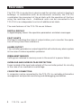
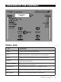
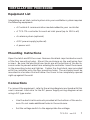
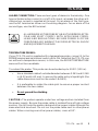
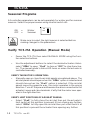
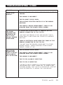
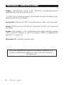
Inlet Controller
TC5-ITA
USER'S MANUAL
M 890-00047
rev. 02
K 895-00458
rev. 00
TABLE OF CONTENTS
PRECAUTIONS ............................................................ 3
FEATURES .................................................................. 4
LOCATION OF THE CONTROLS ..................................... 5
Status Leds ........................................................................ 5
Internal Switches ................................................................. 6
INSTALLATION PROCEDURE ........................................ 7
Equipment List .................................................................... 7
Mounting Instructions ........................................................... 7
Connections ........................................................................ 7
Identification Numbers & End of Line Jumpers ......................... 10
Comlink-2 Location & Connection ......................................... 12
Identifying Primary and Slave Units ....................................... 13
Seasonal Programs ............................................................. 14
Verify TC5-ITA Operation (Manual Mode) .............................. 14
TC5-ITA OPERATION ................................................. 15
Basic Principle of Operation ................................................. 15
Calibration ........................................................................ 18
CONTROLLER FUNCTIONS ......................................... 20
Clock Settings ................................................................... 20
Identification Number ......................................................... 20
Total Opening Time ............................................................ 21
Opening Display ................................................................. 21
Programming Inlet Openings ................................................ 22
Remaining Run Time / Opening Menu ..................................... 23
Resetting the Inlet Position .................................................. 24
Temperature Alarms .......................................................... 27
Alarms - Readout ............................................................... 29
Room Temperature ............................................................ 30
TROUBLESHOOTING GUIDE ....................................... 31
TECHNICAL SPECIFICATIONS .................................... 32
INDEX ...................................................................... 33
2
TC5-ITA rev.02
PRECAUTIONS
Fuses at the input and outputs of the controller adequately protect its
circuitry in the case of an overload or overvoltage. However, we recommend that you install an additional protection device on the
controller's supply circuit to prolong the life of the controller.
The room temperature of the room in which the controller is located
MUST ALWAYS REMAIN BETWEEN 32° AND 104°F (0° AND 40°C).
For indoor use.
To avoid exposing the controller to harmful gases or excessive humidity, it is preferable to install it in a corridor.
DO NOT SPRAY WATER ON THE CONTROLLER
SYMBOLS OF THIS MANUAL
Caution. Carefully read the following text for it contains important information which, if ignored, may cause the controller to operate improperly.
Pay attention. The following text contains useful information.
FOR CUSTOMER USE
Enter below the serial number located on
the side of the controller and retain this
information for future reference.
Model number:
TC5-ITA
Serial number:
TC5-ITA rev.02
3
FEATURES
The TC5-ITA is an electronic device used for air inlet control in livestock
buildings. In combination with an environment controller, the TC5-ITA
coordinates the movement of the air inlets with the operation of the fans
using the real-time clock. Additional units can be connected to the
TC5-ITA for an independent control of additional air inlets.
The main features of the TC5-ITA are as follows:
DIGITAL DISPLAY
A digital display shows the operation parameters and alarm messages.
PILOT LIGHTS
Pilot lights indicating the state of outputs allow you to monitor the operation of the system from a distance.
ALARM OUTPUT
The controller generates an output signal that will activate any alarm system
in the case of various operation problems.
PERMANENT MEMORY
Settings are retained in memory even in the event of a power failure.
OVERLOAD AND OVERVOLTAGE PROTECTION
Fuses located at the input and outputs of the controller protect its circuitry
in the case of an overload or overvoltage.
COMPUTER CONNECTION
A computer can be connected to the TC5-ITA to centralize information
management and provide monitoring and datalogging possibilities.
4
TC5-ITA rev.02
LOCATION OF THE CONTROLS
MAIN MENU
DIGITAL SCREEN
DISPLAY
FUNCTION
SELECTION
BUTTONS
STATUS LEDS
SUB-MENU
BUTTON
ADJUSTMENT
BUTTONS
Status Leds
LED
MEANING
ALARM
Turns on when an alarm is detected.
OPEN
Turns on when the c ontroller opens the air inlet panels .
CLOSE
Turns on when the c ontroller closes the air inlet panels .
LOCKED
Turns on when the parameters are loc ked
and cannot be modified.
ADJUST OPENING
Turns on when the c ontroller waits for the user
to adjust the air inlet opening.
CALIBRATION
Turns on when the c ontroller is in calibration m ode.
MANUAL
Turns on when the actuator is controlled in m anual mode.
INLET RESET
Turns on when the inlet position is being reset.
TC5-ITA rev.02
5
TC5-ITA
Internal Switches
Internal switches are located on the inside of the front cover.
#
OFF
ON
1
UNLOCKED PARAMETERS
LOCKED PARAMETERS
2
FAHRENHEIT DEGREES
CELSIUS DEGREES
3
SUMMER PROGRAM
WINTER PROGRAM
4
DISABLE TEMPERATURE ALARMS
ENABLE TEMPERATURE ALARMS
5
NO TEMPERATURE PROBE
TEMPERATURE PROBE PRESENT
6
SLAVE UNIT
PRIMARY UNIT
7
NO RESET
AUTO RESET THE INLET POSITION
8
RESET MIN POSITION ONLY
RESET TOWARD THE NEAREST POSITION
9
STOP THE MANUAL RESET
START THE MANUAL RESET
10
AM/PM TIME FORMAT
24 HOUR FORMAT
11
OPENING = TIME VALUE
OPENING = %
12
INLET MODE
TUNNEL MODE
6
TC5-ITA rev.02
INSTALLATION PROCEDURE
Equipment List
Integrating an air inlet control system into your ventilation system requires
the following equipment:
• A Comlink-2 communication module added to your controller
• A TC5-ITA controller for each air inlet panel (up to 100 in all)
• An alarm system (optional)
• A DC power supply (optional)
• A power unit.
Mounting Instructions
Open the latch and lift the cover. Remove the black caps located on each
of the four mounting holes. Mount the enclosure on the wall using four
screws. Be sure the electrical knockouts are at the bottom of the enclosure in order to prevent water from entering the controller. Insert the screws
in the mounting holes and tighten. Fasten the four black caps provided
with the controller onto the four mounting holes. The enclosure must be
mounted in a location that will allow the cover to be completely opened
right up against the wall.
Connections
To connect the equipment, refer to the wiring diagrams enclosed with this
user's manual. Also refer to the DC power supply wiring diagram when
using a DC type motor.
•
Use the electrical knockouts provided at the bottom of the enclosure. Do not make additional holes in the enclosure.
•
Set the voltage switch to the appropriate line voltage.
TC5-ITA rev.02
7
TC5-ITA
Environment
Controller
Temperature
Probes
Inlet
Controller
(Primary unit)
Power
Unit
Inlet
Controller
(Slave unit)
Air inlets
INSTALLATION SETUP
Alarm
Inlet
Controller
(Slave unit)
Inlet
Controller
(Slave unit)
TC5-ITA rev.02
8
TC5-ITA
ALARM CONNECTION: There are two types of alarms in the industry. One
type activates when current is cut off at its input, whereas the other activates when current is supplied at its input. For an alarm of the first type,
use the NC terminal as shown on the wiring diagram. For an alarm of the
second type, use the NO terminal.
ALL WIRING MUST BE DONE BY AN AUTHORIZED ELECTRICIAN AND MUST COMPLY WITH APPLICABLE CODES,
LAWS AND REGULATIONS. BE SURE POWER IS OFF BEFORE DOING ANY WIRING TO AVOID ELECTRICAL SHOCK
AND EQUIPMENT DAMAGE.
TEMPERATURE PROBES:
If your TC5-ITA unit is supplied with a temperature probe, connect it to the
PROBE terminal and set internal switch #5 to ON. Note that the TC5-ITA can
run without a temperature sensor; in this case, the ROOM TEMPERATURE
menu will not be a available.
To extend the probe: This probe can be extended up to 500 ft (150 m).
•
Use a shielded cable of outside diameter between 0.245 and 0.260
in (6.22 and 6.60 mm) to ensure the cable entry is liquid-tight (the
cable dimension must not be under 18 AWG).
•
It is preferable to solder the cable joint to ensure a proper contact
between the two cables.
•
Do not ground the shielding.
CAUTION : The probes operate under low voltage and are isolated from
the power supply. Be sure the probe cable is isolated from all high voltage
sources. Do not route the probe cable and other power cables through the
same electrical knockout. Do not run the probe cable next to other power
cables. When crossing over other power cables, cross at 90°.
TC5-ITA rev.02
9
TC5-ITA
Identification Numbers & End of Line Jumpers
Each Comlink-2 card used to communicate parameters between TC5-ITA
units and the main controller must have a unique identification number.
This number is configured using jumpers on the card and should be assigned before plugging the card into each unit. To do this, use the three
jumpers (marked X100, X10 and X1) on the card (i.d. numbers can go from
0 to 199). Use X1 for units, X10 for tens and X100 for hundreds. In each
case, place the black jumper horizontally over the two pins corresponding
to the digit required.
ID JUMPERS
END OF LINE
JUMPERS
The TC5-ITA network operates on two communication lines. One line links
the TC5-ITA units together to the main controller and the other line links
temperature controllers to a computer (this second line is optional). Two
jumpers on the Comlink-2 card are used to identify the end of line for each
communication line. The TC5-ITA communication line uses jumper JP5
and the computer line uses JP4. Use pins 2 and 3 for YES and pins 1 and 2
for NO. The following diagram shows a typical connection with the appropriate jumper configurations.
10
TC5-ITA rev.02
TC5-ITA
INLET
CONTROLLER
(MASTER)
INLET
CONTROLLER
(SLAVE)
INLET
CONTROLLER
(SLAVE)
MAIN
ENVIRONMENT
CONTROLLER
ADDITIONAL
CONTROLLER
ADDITIONAL
CONTROLLER
TC5-ITA rev.02
11
TC5-ITA
Comlink-2 Location & Connection
a. Unplug each unit.
b. Plug the communication card in the unit.
Open the cover. Drill a 5/16" hole through the bottom of the controller and
thread the communication cable through the hole. Use the grommet provided to secure the cable. Connect the cable to the terminals of the communication card as shown below. When connecting two cable ends together, solder the joint and use a heat shrink to ensure a proper contact.
Line-up the comlink card with the connector and insert it in the upright position (see illustration beside). For communication, always use a 1 twisted pair
shielded cable. The maximum length of
the cable is 3000m and the recommended wire diameter is 1.0 mm. Use
a lightning protection module when
running the cable between buildings.
12
TC5-ITA rev.02
COMLINK-2 CARD
TC5-ITA
Be sure the communication cable is isolated from all high
voltage sources and fluorescent lights. Do not route the
communication cable and power cables through the same
electrical knockout. Do not run the communication cable next
to power cables. When crossing power cables, cross at 90°.
DO NOT GROUND THE SHIELD WIRE!
DISCONNECT THE POWER SOURCE BEFORE CONNECTING
THE COMMUNICATION CABLE.
Identifying Primary and Slave Units
If your installation requires more than one TC5-ITA unit for independent
control of different air inlets, one of the TC5-ITA will be configured as the
primary unit and the others will be configured as slaves. Up to 99 slave
units can be connected in this way. When programming the TC5-ITA, the
slave units take their reference temperature from the primary unit. By default, all units are set as PRIMARY units.
•
Set internal switch #6 to ON for the primary unit or
OFF for a slave unit. If only one TC5-ITA unit is used,
set internal switch #6 to ON.
ON
OFF
TC5-ITA rev.02
13
TC5-ITA
Seasonal Programs
All controller parameters can be set separately for winter and for summer
seasons. Select the proper season using internal switch #3 :
ON
OFF
=
=
Winter
Summer
ON
OFF
Make sure to select the right season is selected before
making changes to the parameters.
Verify TC5-ITA Operation (Manual Mode)
•
Power the TC5-ITA then select MANUAL MODE using the function selection buttons.
•
Use the adjustment buttons to select the desired actuator status:
select "OPEn" to open, "CLoS" to close or "OFF" to stop the actuator. The manual mode's status LED turns on when the actuator is
controlled manually.
VERIFY THE MOTOR'S OPERATION:
• Manually open or close the air inlet panels as explained above. The
air inlet panels should open when the "OPEn" option is selected and
should close when the "CLoS" option is selected. If the air inlet
panels move the opposite way, the motor operates in the wrong
direction. Turn off the power and reverse the wires connected to the
actuator's open and close terminals. Verify that the motor now operates in the right direction.
VERIFY LIMIT POSITIONS OF AIR INLET PANELS:
• Select "CLoS" to fully close the air inlet then put the actuator's
limit switch at this position to prevent it from closing any further;
select "OPEn" to fully open the air inlet then put a limit switch at
this position to prevent the actuator from opening any further.
14
TC5-ITA rev.02
TC5-ITA OPERATION
Basic Principle of Operation
The TC5-ITA operates in combination with an environment controller. It
adjusts the air inlet opening according to the ventilation level provided by
this controller. As the temperature increases and new stages are activated, the inlet is opened or closed accordingly. The user must assign a
moving time or an opening percentage to each ventilation stage (or reference point) of the environment controller.
The opening time (or %) of Step 0 defines the initial position of the air inlet
and corresponds to a room temperature of 0.4°F (0.2°C) below the controller set point. This normally corresponds to the minimum ventilation cycle.
INLET OPENING
(in seconds or
% of the Total
Opening Time)
Opening of the Air Inlet
based on Ventilation Stages
TOTAL
OPENING TIME
STEP 3
STEP 2
STEP 1
HI
STEP 1
STEP 0
CLOSED
0.4 °F
STEP 0
Bandwidth Offset
Stage 1
starts
Stage 2
starts
Stage 3
starts
ROOM
TEMP.
SET POINT
Inlet & Tunnel Modes:
When the last reference point is reached, the TC5-ITA can either open the
air inlet according to a user-defined value (internal switch #12 to OFF), or
it can fully open the air inlet up until the inlet reaches its limit switch
(internal switch #12 to ON).
TC5-ITA rev.02
15
TC5-ITA
Opening of the Air Inlet During Variable Stages
A step is also added when a variable stage starts increasing in speed, right
after the stage's differential. This step is called “ Step x Hi ”. The step
number is not increased as we are dealing with the same ventilation stage.
In the previous graph, Step 1 corresponds to the activation of Stage 1 and
Step 1 Hi signals the point where Stage 1 fans reach their full speed.
The user must thus define the inlet opening position (in time or %) required
at the beginning and at the end of each variable stage. Once this is done,
the user can choose to subdivide this opening time or % into 0 to 2 intermediate opening steps to progressively open the inlet during the variable
stage.
When intermediate opening steps are enabled, the controller splits up the
variable stage's opening time or % evenly between the number of intermediate steps (e.g., if one intermediate step is enabled, the controller will
open the inlet two times during the variable stage (open 50% of the variable stage's opening time (or %) at the first intermediary step, 50 % at the
end of the variable stage).
Intermediate steps are activated when the variable stage reaches predefined fan speeds. These fan speeds are set differently depending on the
number of intermediate steps in use. For example, if 1 intermediate step is
enabled, the inlet opens during half the variable stage's opening when the
stage's speed is of 75 %;
it reaches the stage's HI
opening position when the
Opening of the Inlet
fan speed is 100 %.
During a Variable Stage
The three following graphs
illustrate when each intermediate step starts.
with 0 Intermediate Step
Opening
(Time or %)
Step HI
Opening
Step
Opening
50 %
16
TC5-ITA rev.02
100 %
Variable
Stage
Speed
TC5-ITA
Opening
(Time or %)
Opening of the Inlet
During a Variable Stage
with 1 Intermediate Step
Step HI
Opening
1/2
Intermediary
Step 1
1/2
Step
Opening
50 %
Opening
(Time or %)
Intermediary
Step 2
1/3
Step
Opening
100 %
Opening of the Inlet
During a Variable Stage
with 2 Intermediate Steps
Step HI
Opening
1/3
75 %
(interm.
step 1)
Variable
Stage
Speed
Intermediary
Step 1
1/3
50 %
60 %
85 %
(interm. (interm.
step1)
step2
100 %
Variable
Stage
Speed
Refer to the PROGRAMMING chapter to enable the proper number of
intermediate opening steps.
TC5-ITA rev.02
17
TC5-ITA
Calibration
The TC5-ITA adjusts the opening of air inlets according to the ventilation
stages provided by the environment controller. The calibration allows
TC5-ITA units to detect how many On/Off and variable stages the environment controller uses.
When the calibration is launched on the PRIMARY TC5-ITA unit, the environment controller enters in test mode and starts simulating the room temperature. The controller increases the simulated room temperature in order to activate all of its ventilation stages. Each time a stage is activated,
a reference point is added to the TC5-ITA.
BEFORE CALIBRATING THE TC5-ITA:
18
•
It is preferable to calibrate the TC5-ITA while the room is empty
because the calibration will cause the activation of all fan stages.
•
Be sure that the circuit breakers at the service panel and all other
protection devices are in a position such that the fans can be activated.
•
Select the season you want to program with internal switch #3.
TC5-ITA rev.02
TC5-ITA
CALIBRATION SETTINGS:
1.
Select CALIBRATION using the function selection buttons
2.
Press and hold the right-arrow key for 2 seconds on the primary
TC5-ITA unit to start the calibration.
3.
Once the calibration is launched, press and hold the right-arrow
key for 2 seconds on all TC5-ITA slave units within the next 30 seconds.
4.
After 30 seconds, the environment controller enters in test mode
and starts simulating the room temperature. The simulated room
temperature gradually increases for TC5-ITA units to detect the
number of On/Off and variable ventilation stages in use.
5.
After the environment controller has reached the start temperature of its last ventilation stage, press and hold the right-arrow key
of the PRIMARY TC5-ITA unit for 2 seconds to end the calibration.
You can also wait for the environment controller to reach 120°F
(49°C) – the calibration will automatically end at that moment.
One reference point per ventilation stage will then be added to
each calibrated TC5-ITA.
6.
Refer to the programming chapter to assign an inlet opening to
each reference point.
TC5-ITA rev.02
19
CONTROLLER FUNCTIONS
Clock Settings
•
Select "CLOCK" using the function selection buttons.
•
Press the right-arrow key once. The hours flash on the display.
•
Use the adjustment buttons to set the hours to the desired value.
•
Press the right-arrow key. The minutes flash on the display.
•
Use the adjustment buttons to set the hours to the desired value.
Identification Number
This function displays the identification number of the TC5-ITA along with
its primary/slave status. The identification number is set using jumpers on
the COMLINK-2 communication card (see INSTALLATION PROCEDURE
chapter).
To display the identification number:
•
20
Select "IDENTIFICATION NUMBER" using the function selection
buttons. The identification number is displayed, alternating with
"ID" and "PRI" or "SLA" for a primary or slave unit.
TC5-ITA rev.02
TC5-ITA
Total Opening Time
You must specify the exact time that is required for the actuator to reach
its maximum limit switch. The actuator's opening will then be limited by
this opening time.
Set this parameter before
calibrating the inlets.
•
Select "TOTAL OPENING TIME" using the function selection buttons. The time that is required to fully open the air inlet is displayed
(in seconds).
•
Use the adjustment buttons to set the total opening time to the
desired value.
•
Proceed in similar fashion to set the total opening time on all
TC5-ITA units.
Opening Display
The user must assign an inlet position to each ventilation stage. This position can either be specified as a moving time of the actuator or as a percentage of the total run time. When the percentage method is used, the
controller converts the inlet's moving times into a percentage based on the
total run time of the inlet.
Choose the desired opening display method:
•
•
Time value:
%
internal switch #11 is OFF
internal switch #11 is ON.
ON
OFF
11
Note that displaying the inlet opening as a time value
offers a little more precision than the percentage
display.
TC5-ITA rev.02
21
TC5-ITA
Programming Inlet Openings
Once the calibration is completed, you must assign an inlet position to each
ventilation stage of the environment controller. This position can either be
specified as a moving time of the actuator or as a percentage of the total run
time, depending on the chosen option (see OPENING DISPLAY chapter).
BEFORE PROGRAMMING INLET OPENINGS
•
Install a static pressure measuring device or determine in advance
the position required at each reference point by calculating, according to the fan airflow, the opening that will maintain the desired air speed at the inlet.
•
Enter the total opening time of the inlet of each TC5-ITA unit.
PROGRAMMING INLET OPENINGS:
•
Select "PROGRAMMING" using the function selection buttons (note
that this menu is not available during the calibration) The opening
time or the inlet position (in %) associated with step 0 is displayed.
Moving times are displayed as follows:
- A negative time value signals a closing time;
- A positive time value signals an opening time;
- The word "Off" means that the inlet completely closes once
the temperature controller reaches the selected step.
22
•
Use the adjustment buttons to specify the opening time or the inlet
position (%) associated with step 0 (if required).
•
Press the right-arrow key to select the next step.
•
Use the adjustment buttons to specify the opening time that needs
to be added to the previous opening, or to specify the inlet opening
(in %) associated with the selected step.
•
Proceed in similar fashion for all steps.
TC5-ITA rev.02
TC5-ITA
The cummulative opening times of an air inlet cannot exceed the inlet's Total Opening Time parameter value.
If the opening of the air inlet is set as a percentage, the
controller may have to sligthly adjust the inlet opening values due to some internal restriction in the conversion process.
SELECTING THE NUMBER OF INTERMEDIATE OPENING STEPS
Follow this procedure to select the number intermediate opening steps
that are performed during variable stages (see BASIC PRINCIPLE OF
OPERATION chapter for further information).
•
Select "REMAINING RUN TIME / OPENING" using the function selection buttons.
•
Press and hold the right-arrow key for 2 seconds. The number of
intermediate steps flashes, alternating with the letters "NbS" and
"StEP.
•
Use the adjustment buttons to set the number of intermediate steps
to the desired value. This value ranges from 0 to 2 steps.
Remaining Run Time / Opening Menu
If the inlet opening is displayed as a time value (internal switch #11 is OFF),
the REMAINING RUN TIME / OPENING menu shows a countdown of the
remaining moving time of the air inlet (opening or closing time). A negative
value is displayed when the inlet is closing. The letters "STOP" are displayed if the inlet is not moving.
If the inlet opening is displayed as a percentage, the REMAINING RUN
TIME / OPENING menu shows the current opening (in %) of the air inlet.
TC5-ITA rev.02
23
TC5-ITA
Resetting the Inlet Position
Resetting the actuator’s position allows clearing all accumulated time offets
caused by the frequent openings and closings of the inlet. It is highly suggested to reset the inlet positions frequently to make sure they are always
accurate.
Choose a Resetting Method:
The inlet reset can be done in two different ways:
1.
2.
Reset the minimum position only:
The inlet closes during the Reset Time Delay each
time a reset is performed. Once the inlet position is
reset, the inlet returns to its previous position. Set
internal switch #8 to OFF to use this reset method.
Reset toward the nearest position
Each time a reset starts, the inlet panel is directed
towards the closest position from its current opening: it then opens or closes during the Reset Time
Delay. Once the reset is completed, the inlet returns
to its previous position. This function prevents closing the air inlet when the room temperature already
asks for a large opening of the panel. Set internal
switch #8 to ON to use this reset method.
This resetting method requires the presence of limit switches at both ends of
the actuator.
24
TC5-ITA rev.02
ON
OFF
ON
OFF
TC5-ITA
Adjust the Reset Delay:
This is the delay that is required to fully open / close the inlet panel in order
to reset the inlet position. The reset delay of an inlet must be greater than
its total opening time. This ensures the inlet panel to be completely opened
or closed while its position is being reset.
The Reset Delay can be adjusted from 60 to 900 seconds in increments of
15 seconds.
•
Select "RESET SETTINGS" using the function selection buttons.
•
Press the right-arrow key until the Reset Delay is displayed alternating with letters "dEL".
•
Use the adjustment buttons to set the Reset Delay to the desired
value.
•
Proceed in similar fashion to set the Reset Delay on all
TC5-ITA units.
Manual & Automatic Resets
The reset of an inlet can either be performed manually (which is useful
when the user detects an offset in the inlet position) and/or it can be performed at regular intervals (auto-reset).
Manual Reset:
To perform a manual reset, switch internal switch #9
from OFF to ON.
Automatic Reset:
Set internal switch #7 to ON to enable the autoreset function then program the auto-reset settings
as explained in the following section.
ON
OFF
ON
OFF
TC5-ITA rev.02
25
TC5-ITA
AUTO-RESET SETTINGS:
The following procedure shows how to specify the frequency at which
automatic resets are performed.
SINCE THE RESETS MAY CAUSE THE CLOSURE OF
AIR INLETS, DO NOT PROGRAM THE RESET OF ALL
INLETS SIMULTANEOUSLY.
26
•
Select "RESET SETTINGS" using the function selection buttons.
The hour at which the auto-reset is performed flashes on the display. Note that this menu is only accessible if the auto-reset function is enabled (internal switch #7 is ON).
•
Use the adjustment buttons to set the hour to the desired value.
•
Press the right-arrow key once. The minutes flash on the display.
•
Use the adjustment buttons to set the minutes to the desired value.
•
Press the right-arrow key. The frequency at which auto-resets are
performed is displayed, alternating with the letters "PEr".
•
Use the adjustment buttons to set the frequency to the desired
value. The frequency can be adjusted once every 1 to 7 days. Select "1" to reset the position every day; select "2" to reset the
position every 2 days, etc.
TC5-ITA rev.02
TC5-ITA
Temperature Alarms
Low Temperature Alarm:
The alarm contact is activated when the room temperature drops below
"temperature set point- low alarm offset" as shown below. The Lo Offset
is the temperature difference from the set point below which a low temperature alarm is set off. It can be adjusted from 0.5°F to 20°F (0.3°C to
11.1°C). Note that internal switch #4 must be set to ON for this alarm to
be detected.
High Temperature Alarm:
The alarm contact is activated when the room temperature exceeds "temperature set point + high alarm offset" as shown below. The Hi Offset is
the temperature difference from the set point above which a high temperature alarm is set off. It can be adjusted from 0.5°F to 40°F (0.3°C to
22.2°C). Note that internal switch #4 must be set to ON for this alarm to
be detected.
TEMPERATURE
HI OFFSET
HI TEMPERATURE
ALARM
LO OFFSET
SET POINT
LO TEMPERATURE
ALARM
TIME
TC5-ITA rev.02
27
TC5-ITA
ALARM SETTINGS:
28
•
Select "ALARM SETTINGS" using the function selection buttons.
The Low Alarm Offset flashes on the display alternating with the
letters "Lo". Note that this menu is only accessible it temperature
alarms are enabled (internal switch #4 is ON).
•
Use the adjustment buttons to adjust the Lo Offset to the desired
value.
•
Press the right-arrow key once. The Hi Offset flashes on the display alternating with the letters "Hi".
•
Use the adjustment buttons to adjust the Hi Offset to the desired
value.
TC5-ITA rev.02
TC5-ITA
Alarms - Readout
When an alarm occurs, the TC5-ITA activates the alarm contact and turns
on the alarm pilot light. The alarm readout function displays all currently
outstanding alarm situations.
•
Select "ALARM READOUT" using the function selection buttons.
The following codes can be displayed on screen:
ALARM CODE
MEAN ING
AL1
The communication between the TC 5-ITA and the
environment controller is disrupted.
AL2
The calibration is not valid.
AL3
the temperature probe is defective or is not connected
properly.
AL4
Low temperature alarm.
AL5
High temperature alarm.
AL6
Reception of an unprogrammed stage
NoAL
There is no active alarm.
TC5-ITA rev.02
29
TC5-ITA
Room Temperature
This function gives a readout of the current room temperature. Minimum
and maximum temperature values can also be displayed. Internal switch
#5 must be set to ON and a temperature probe must be connected for this
function to work.
If you let the display flash for more than 10 seconds, the controller resets the minimum and maximum temperature values
currently in memory. In other words, the two values are reset
to the current room temperature. To avoid resetting minimum
and maximum values, return to the current opening display
using the adjustment buttons before the 10 second delay has
elapsed.
30
•
Select "ROOM TEMPERATURE" using the function selection buttons.
The current room temperature is displayed.
•
Press the adjustment buttons' up arrow-key once. The maximum
temperature value is displayed alternating with the letters "Hi".
•
Press the adjustment buttons' down-arrow key once. The current
room temperature is displayed once again.
•
Press the adjustment buttons' down arrow-key once again. The
minimum temperature value is displayed alternating with the letters "Lo".
TC5-ITA rev.02
TROUBLESHOOTING GUIDE
PROBLEM
SOLUTION
THERE IS NO
DISPLAY.
THE CIRCUIT BREAKER AT THE SERVICE PANEL IS OFF OR
TRIPPED.
THE WIRING IS INCORRECT.
THE F10 INPUT FUSE IS OPEN.
THE VOLTAGE SELECTOR SWITCH IS IN THE WRONG
POSITION.
THE DISPLAY BOARD INTERCONNECT CABLE IS UNPLUGGED FROM THE POWER SUPPLY BOARD.
THE ROOM
TEMPERATURE
DISPLAYED BY
THE TC5-ITA
SHOWS SUDDEN
VARIATIONS.
A VARIATION IN RESISTANCE IS INDUCED ON THE
SENSOR CONNECTED TO THE TC5-ITA
- BE SURE THE SENSOR IS DRY AND MOVE IT AWAY
FROM DRAFTS AND FROM ANY SOURCE OF RADIANT
HEATING.
THERE IS ELECTRICAL NOISE NEAR THE CABLE OF THE
SENSOR CONNECTED TO THE TC5-ITA.
- DO NOT RUN THE SENSOR CABLE NEXT TO OTHER
POWER CABLES. WHEN CROSSING OTHER POWER
CABLES, CROSS AT 90°.
THE TC5-ITA
ALARM PILOT
LIGHT IS ON BUT
THE ALARM IS
NOT ACTIVATED.
THE F9 ALARM FUSE IS OPEN.
THE DISPLAY BOARD INTERCONNECT CABLE IS UNPLUGGED FROM THE POWER SUPPLY BOARD.
THE WIRING IS INCORRECT.
THE TC5-ITA ALARM IS DEFECTIVE.
THE TC5-ITA IS DEFECTIVE.
- LISTEN TO SEE IF THERE IS A CLICKING SOUND WHEN
THE ALARM PILOT LIGHT TURNS ON. IF THERE IS NO
CLICKING SOUND, THE TC5-ITA IS DEFECTIVE. CONTACT
YOUR DISTRIBUTOR TO REPAIR THE CONTROLLER.
TC5-ITA rev.02
31
TECHNICAL SPECIFICATIONS
Supply: - 115/230 VAC (- 18%, + 8%), 50/60 Hz, overload and overvoltage protection fuse F10-1A fast blow.
- 12 VDC for AC back-up supply, can activate the inlet and alarm if supplied with DC back-up voltage.
Power unit: 50/60 Hz, 30 VDC, 5A motor output, fuse F1-5A slow blow.
Alarm: ON-OFFoutput, 115/230 VAC, 50/60 Hz, 30 VDC, 3A, fuse F9-3A
slow blow.
Probes: Low voltage ( < 5V), isolated from the supply. Operating range:
-40.0° to 120.0°F(-40.0° to 49°C). Accuracy: 1.8oF (1°C) between 41o
and 95oF (5° and 35°C).
Enclosure: ABS, humidity and dust-tight.
The room temperature where the controller is located MUST
ALWAYS REMAIN BETWEEN 32o AND 104oF (0o AND 40oC).
For indoor use.
32
TC5-ITA rev.02
INDEX
A
D
Actuator see Inlet
Dip switches 6
Alarms
F
Conditions 29
Connection 9
Readout 29
Temperature alarms
Activation 6
Principle of operation 27
Settings 28
Fahrenheit units 6
I
ID number see Comllink-2 card
Inlet
Calibration 18–19
Inlet mode
Activation 6
Principle of operation 15
Limit switch positionning 14
Manual activation 14
Principle of operation 15
Programming the steps 22
Reset see Reset
Total opening time 21
Variable stage opening
Principle of operation 16
Settings 23
B
Buttons 5
C
Calibration 18–19
Celsius units 6
Clock
Format selection (AM/PM - 24h) 6
Time settings 20
Comlink-2 card
End of line jumpers
Principle of operation 10
Identification numbers
Principle of operation 10
Location & connection 12
Communication card
see Comlink-2 card
Connections 7–9
Controller
ID number 10
Model number 3
Mounting instructions 7
Primary / slave modules
Principle of operation 13
Settings 6
Serial number 3
Setup 8
Status leds 5
Technical specifications 32
Inlet opening display 6
Installation 7
Setup 8
Internal switches 6
J
Jumpers see Comlink-2 card
K
Keys 5
L
Leds 5
Limit switch positionning 14
TC5-ITA rev.02
33
TC5-ITA
M
Manual mode 14
Temperature alarms see Alarms
Temperature probe activation 6
Unit selection : °F or °C 6
Motor see Inlet
Time see Clock
Mounting instructions 7
Troubleshooting guide 31
P
Tunnel mode
Parameters
Lock / unlock parameters 6
Activation 6
Principle of operation 15
Pilot lights 5
W
Primary unit
Winch see Inlet
Principle of operation 13
Settings 6
Probes
Activation 6
Extension 9
Problems
Troubleshooting guide 31
Programs (seasonal) 6
R
Reset
Activation 6
Principle of operation 24
Settings 25–26
S
Seasonal program selection
6, 14
Sensors see Probes
Serial number 3
Slave unit
Principle of operation 13
Settings 6
Summer program 6
T
Technical specifications 32
Temperature
Room temperature 30
34
TC5-ITA rev.02
Winter program 6
Wiring 7–9
Precautions 3