1
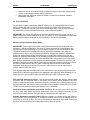
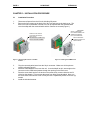
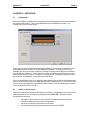
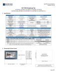
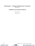
Supplement for
HE-XRC9
900MHz Modem
COM Module
SUP0823-01
PAGE 2
19 MAR 2007
SUP0823-01
PREFACE
This manual explains how to use the HE-XRC9 XLe 900MHz Modem COM Module.
Copyright (C) 2006 Horner APG, LLC., 59 South State Avenue, Indianapolis, Indiana 46201. All
rights reserved. No part of this publication may be reproduced, transmitted, transcribed, stored in
a retrieval system, or translated into any language or computer language, in any form by any
means, electronic, mechanical, magnetic, optical, chemical, manual or otherwise, without the
prior agreement and written permission of Horner APG, Inc.
All software described in this document or media is also copyrighted material subject to the terms
and conditions of the Horner Software License Agreement.
Information in this document is subject to change without notice and does not represent a
commitment on the part of Horner APG.
Cscape, SmartStack, SmartStix and CsCAN are trademarks of Horner APG.
Ethernet is a trademark of Xerox Corporation.
Micro SD and CompactFlash are registered trademarks of SanDisk Corporation.
MS-DOS, Microsoft, Windows 95, Windows 98, Windows 2000, Windows NT, and Windows XP
are trademarks of Microsoft Corp.
For user manual updates, contact Technical Support:
North America:
(317) 916-4274
www.heapg.com
email: [email protected]
Europe:
(+) 353-21-4321-266
www.horner-apg.com
email: [email protected]
SUP0823-01
19 MAR 2007
PAGE 3
LIMITED WARRANTY AND LIMITATION OF LIABILITY
Horner APG, LLC. ("HE-APG") warrants to the original purchaser that the HE-XRC9 XLe 900MHz
Modem COM Module manufactured by HE-APG is free from defects in material and workmanship
under normal use and service. The obligation of HE-APG under this warranty shall be limited to
the repair or exchange of any part or parts which may prove defective under normal use and service
within two (2) years from the date of manufacture or eighteen (18) months from the date of installation by the
original purchaser whichever occurs first, such defect to be disclosed to the satisfaction of HE-APG after
examination by HE-APG of the allegedly defective part or parts. THIS WARRANTY IS EXPRESSLY IN
LIEU OF ALL OTHER WARRANTIES EXPRESSED OR IMPLIED INCLUDING THE WARRANTIES OF
MERCHANTABILITY AND FITNESS FOR USE AND OF ALL OTHER OBLIGATIONS OR LIABILITIES AND
HE-APG NEITHER ASSUMES, NOR AUTHORIZES ANY OTHER PERSON TO ASSUME FOR HE-APG,
ANY OTHER LIABILITY IN CONNECTION WITH THE SALE OF THIS HE-XRC9 XLe 900MHz Modem
COM Module. THIS WARRANTY SHALL NOT APPLY TO THIS HE-XRC9 XLe 900MHz Modem COM
Module OR ANY PART THEREOF WHICH HAS BEEN SUBJECT TO ACCIDENT, NEGLIGENCE,
ALTERATION, ABUSE, OR MISUSE. HE-APG MAKES NO WARRANTY WHATSOEVER IN RESPECT TO
ACCESSORIES OR PARTS NOT SUPPLIED BY HE-APG. THE TERM "ORIGINAL PURCHASER", AS
USED IN THIS WARRANTY, SHALL BE DEEMED TO MEAN THAT PERSON FOR WHOM THE HEXRC9 XLe 900MHz Modem COM Module IS ORIGINALLY INSTALLED. THIS WARRANTY SHALL
APPLY ONLY WITHIN THE BOUNDARIES OF THE CONTINENTAL UNITED STATES.
In no event, whether as a result of breach of contract, warranty, tort (including negligence) or otherwise,
shall HE-APG or its suppliers be liable of any special, consequential, incidental or penal damages including,
but not limited to, loss of profit or revenues, loss of use of the products or any associated equipment,
damage to associated equipment, cost of capital, cost of substitute products, facilities, services or
replacement power, down time costs, or claims of original purchaser's customers for such damages.
To obtain warranty service, return the product to your distributor with a description of the problem,
proof of purchase, post paid, insured and in a suitable package.
ABOUT PROGRAMMING EXAMPLES
Any example programs and program segments in this manual or provided on accompanying
diskettes are included solely for illustrative purposes. Due to the many variables and
requirements associated with any particular installation, Horner APG cannot assume
responsibility or liability for actual use based on the examples and diagrams. It is the sole
responsibility of the system designer utilizing the HE-XRC9 XLe 900MHz Modem COM Module to
appropriately design the end system, to appropriately integrate the HE-XRC9 XLe 900MHz
Modem COM Module and to make safety provisions for the end equipment as is usual and
customary in industrial applications as defined in any codes or standards which apply.
Note:
The programming examples shown in this manual are for illustrative purposes
only. Proper machine operation is the sole responsibility of the system integrator.
PAGE 4
19 MAR 2007
SUP0823-01
Table of Contents
LIMITED WARRANTY AND LIMITATION OF LIABILITY ..............................................................3
CHAPTER 1: SAFETY / COMPLIANCE ........................................................................................5
1.1 Safety Warnings and Guidelines ........................................................................................ 5
CHAPTER 2: INTRODUCTION ......................................................................................................7
2.1 Overview............................................................................................................................. 7
2.2 Technical Support Contacts ............................................................................................... 7
CHAPTER 3: INSTALLATION PROCEDURE ...............................................................................8
3.1 Installation Procedure......................................................................................................... 8
CHAPTER 4: OPERATION.............................................................................................................9
4.1 Configuration ...................................................................................................................... 9
4.2 Ladder communications ..................................................................................................... 9
SUP0823-01
19 MAR 2007
PAGE 5
CHAPTER 1: SAFETY / COMPLIANCE
1.1
Safety Warnings and Guidelines
When found on the product, the following symbols specify:
Warning: Consult user documentation.
Warning: Electrical Shock Hazard.
WARNING: This equipment is approved only for mobile and base station transmitting devices.
Antenna(s) used for this transmitter must be installed to provide a separation distance of at
least 30 cm from all persons and must not be co-located or operating in conjunction with any
other antenna or transmitter.
NOTE: The separation distance indicated in the above is 30 cm, but any distance greater than
or equal to 23 cm can be used (per MPE evaluation).
WARNING: To avoid the risk of electric shock or burns, always connect the safety (or earth)
ground before making any other connections.
WARNING: To reduce the risk of fire, electrical shock, or physical injury it is strongly
recommended to fuse the voltage measurement inputs. Be sure to locate fuses as close to the
source as possible.
WARNING: Replace fuse with the same type and rating to provide protection against risk of
fire and shock hazards.
WARNING: In the event of repeated failure, do not replace the fuse again as a repeated failure
indicates a defective condition that will not clear by replacing the fuse.
WARNING: Only qualified electrical personnel familiar with the construction and operation of
this equipment and the hazards involved should install, adjust, operate, or service this
equipment. Read and understand this manual and other applicable manuals in their entirety
before proceeding. Failure to observe this precaution could result in severe bodily injury or
loss of life.
•
•
All applicable codes and standards need to be followed in the installation of this product.
For I/O wiring (discrete), use the following wire type or equivalent: Belden 9918, 18 AWG
or larger.
Adhere to the following safety precautions whenever any type of connection is made to the
module.
•
•
•
•
•
•
Connect the green safety (earth) ground first before making any other connections.
When connecting to electric circuits or pulse-initiating equipment, open their related
breakers. Do not make connections to live power lines.
Make connections to the module first; then connect to the circuit to be monitored.
Route power wires in a safe manner in accordance with good practice and local codes.
Wear proper personal protective equipment including safety glasses and insulated gloves
when making connections to power circuits.
Ensure hands, shoes, and floor are dry before making any connection to a power line.
PAGE 6
•
•
19 MAR 2007
SUP0823-01
Make sure the unit is turned OFF before making connection to terminals. Make sure all
circuits are de-energized before making connections.
Before each use, inspect all cables for breaks or cracks in the insulation. Replace
immediately if defective.
1.2 FCC Compliance
The HE-XRC9 contains a MaxStream OEM RF module, FCC ID: OUR-9XTEND The enclosed
device complies with Part 15 of the FCC Rules. Operation is subject to the following two
conditions: (i.) this device may not cause harmful interference and (ii.) this device must accept
any interference, including interference that may cause undesired operation.
IMPORTANT: The XTend OEM RF Module has been certified by the FCC for use with other
products without any further certification (as per FCC section 2.1091). Modifications not expressly
approved by MaxStream could void the user's authority to operate the equipment.
Effective Isotropic Radiated Power (EIRP)
IMPORTANT: Power output is conducted at the antenna terminal and can be adjusted from 1
milliwatt to 1 Watt at the OEM level. This is an RF module approved for Limited Modular use
operating as a mobile transmitting device with respect to section 2.1091 and is limited to OEM
installation for Mobile and Fixed applications only. During final installation, end-users are
prohibited from access to any programming parameters. Professional installation adjustment is
required for setting module power and antenna gain to meet EIRP compliance for high gain
antenna(s). Final antenna installation and operating configurations of this transmitter including
antenna gain and cable loss must not exceed the EIRP of the configuration used for calculating
MPE. Grantee (MaxStream) must coordinate with OEM integrators to ensure the end-users and
installers of products operating with the module are provided with operating instructions to satisfy
RF exposure requirements. The FCC grant is valid only when the device is sold to OEM
integrators. Integrators are instructed to ensure the end-user has no manual instructions to
remove, adjust or install the device.
FCC regulations stipulate a 36 dBm EIRP power requirement. Users implementing antenna gain
greater than 6.0 dB must compensate for the added gain with cable loss. When operating at 1 W
power output, the sum (in dB) of cable loss and antenna gain shall not exceed 6.0 dB.
FCC-approved Antennas WARNING: This device has been tested with Reverse Polarity SMA
connectors with the antennas listed in the tables of this section. When integrated into OEM
products, fixed antennas require installation preventing end-users from replacing them with nonapproved antennas. Antennas not listed in the tables must be tested to comply with FCC Section
15.203 (unique antenna connectors) and Section 15.247 (emissions).
Fixed Base Station and Mobile Applications MaxStream RF Modules are pre-FCC approved
for use in fixed base station and mobile applica-tions. When the antenna is mounted at least
20cm (8") from nearby persons, the application is considered a mobile application.
Portable Applications and SAR Testing When the antenna is mounted closer than 20cm to
nearby persons, then the application is considered "portable" and requires an additional test be
performed on the final product. This test is called Specific Absorption Rate (SAR) testing and
measures the emissions from the module and how they affect the person.
SUP0823-01
19 MAR 2007
PAGE 7
CHAPTER 2: INTRODUCTION
2.1
Overview
To supplement the built-in MJ1 and MJ2 serial ports on the XLe, the 900MHz modem optional
COM module (HE-XRC9) can be installed internal to the XLe to provide 900MHz spread
spectrum communications. This optional COM module provides a cost savings over an external
modem and reduces the amount of consumed space.
The HE-XRC9 has the following features:
Topology
Frequency
Encryption
Power
Indoor range
Outdoor range
Transfer rate
- Spread spectrum (HSFF)
- ISM 908-928 MHz
- 256bit AES
- 1mW to 1 watt (adjustable to match antenna to maximum EIRP)
- up to 3000 feet
- up to 40 miles (line-of-sight)
- 9.6k or 115.2k (range reduced at higher baud rate)
The HE-XRC9 allows spread spectrum communications through ladder communication function
blocks when the MJ1/Com Option port is opened in Radio 900MHz mode via the OPEN function
block. The SEND function block may then be used to initialize the operating parameters utilizing
Hayes AT style commands (such as source and destination IDs). Once the HE-XRC9 is
initialized and an AT style command to exit command mode is issued; thereafter, either the
SEND/RECV or MODBUS function blocks may be then used to transfer data.
The HE-XRC9 utilizes the same internal communications channel (UART) as the MJ1 serial port;
thus, enabling the HE-XRC9 deactivates the MJ1 serial port. However, support is provided to
select which device is currently active through ladder control.
The HE-XRC9 is provided connection to the internal handshake lines of RTS and CTS. As such,
the OPEN function block handshake parameter of hardware is functional if the HE-XRC9 is
programmed appropriately. Additionally, software handshaking (XON/XOFF) is also available if
both the OPEN function block and the HE-XRC9 is programmed appropriately.
Included with the HE-XRC9 is an articulated 1/2-wave dipole RPSMA antenna (2.1 db gain).
The HE-XRC9 internally uses the MaxStream 9XTend 900MHz OEM core. For additional
technical information, certifications or extended AT command set information, see
www.maxstream.net
2.2
Technical Support Contacts
For manual updates and assistance, contact Technical Support at the following locations:
North America:
(317) 916-4274
www.heapg.com
email: [email protected]
Europe:
(+) 353-21-4321-266
www.horner-apg.com
email: [email protected]
PAGE 8
19 MAR 2007
SUP0823-01
CHAPTER 3: INSTALLATION PROCEDURE
3.1
Installation Procedure
1.
2.
Disconnect all power from the XLe unit including I/O power.
Remove the four screws on the back of the XLe unit and remove the back cover. The
back cover can be discarded or saved, but it will be replaced with the extended back
cover that ships with the communication add-on. Screws are re-used (Figure 1).
001XLE058
REMOVE FOUR SCREWS
AS SHOWN AND REMOVE
BACK COVER.
DISCARD BACK COVER ONLY!
DO NOT DISCARD SCREWS!
Figure 1 - Removing Back Cover of the XLE
the XLE
3.
4.
5.
6.
INSTALL COM BOARD
BY ALIGNING CONNECTOR
AND SEATING BOARD
FULLY ON STANDOFFS.
INSTALL NEW BACK
COVER RE-USING THE
FOUR SCREWS.
Figure 2 - Installing the COM Board in
Plug the communication board onto the 24-pin connector. Make sure all the pins are
properly aligned (Figure 2).
Place the extended back cover onto the unit. It can be helpful to tip it at an angle so the
connector on the COM board passes through the opening on the back cover.
Place the screw back into the hole and turn the screw slowly counter clockwise until it
clicks into the threads. This prevents the screw from being cross-threaded. Now, turn
the screw clock-wise until the cover is firmly secured. Repeat this process for all four (4)
screws.
Install the included antenna.
SUP0823-01
19 MAR 2007
PAGE 9
CHAPTER 4: OPERATION
4.1
Configuration
Once the HE-XRC9 is installed, the corresponding CSCAPE application must be made aware of
the optional COM module. This is accomplished through the CSCAPE: Controller -> I/O
Configuration menu as shown below:
If the target XLe (with the HE-XRC9 installed) is available and connected to CSCAPE, the Auto
Config System will fill the EMPTY slot with HEXRC9 information. If the target XLe is NOT
available, the user may manually configure by clicking the Config button adjacent to the EMPTY
slot and selecting HEXRC9 – radio modem option card (this assumes that XLE has previously
been selected as the Controller). Thereafter, on exiting the I/O Configuration dialog by clicking
the OK button, the application is configured for the HE-XRC9.
Failure to set HEXRC9 in the I/O Configuration when attempting to download an application that
uses an OPEN function block set to Radio 900 generates a download error. Even if the HE-XRC
9 is not used by the application, the HEXRC9 must still be set in the I/O Configuration to prevent
an I/O Configuration error on the XLe.
4.2
Ladder communications
To access the HE-XRC9 optional COM module from ladder, the application must first execute an
OPEN function block for MJ1/Option port with Mode set to Radio 900. This function block
accomplishes three tasks:
•
•
•
Serial port is disconnected from the CSCAPE command interpreter and made
available to ladder communications function blocks.
Serial port is internally connected to the HE-XRC9.
Serial port transfer rate and frame protocol set to match HE-XRC9
PAGE 10
19 MAR 2007
SUP0823-01
The OPEN function block Baud rate and frame parameters (Parity, Data bits, etc…) must be set
to match that of the HE-XRC9. The factory default setting of these parameters are 9600, 8, N,
and 1. It is possible to program the HE-XRC9 for a different baud rate and frame protocol and
save those values to non-volatile memory; however, it is left to the user to record those values
and set the OPEN function block appropriately.
Once the MJ1/Option port is opened in Radio 900 mode, it is ready to start transmitting data;
however, it may be desired to change modes of operation, source and destination addresses, or
add encryption. This requires entering command mode though the sending of a “+++” sequence
to the HE-XRC9 followed by the appropriate “AT” commands by using SEND function blocks.
The “AT” commands and corresponding transmit modes are covered in detail in the MaxStream
9Xtend OEM RF Module – Product Manual, available at:
http://www.maxstream.net/products/xtend/product-manual_XTend_OEM_RF-Module.pdf .
When transferring data, handshaking is generally not required for messages less than 2K
bytes. The HE-XRC9 breaks larger messages into smaller packets for transfer between HEXRC9 modems. Note that Modbus RTU communications may be unreliable if the HE-XRC9
packet size or transfer method is not configured for complete RTU message transfer without
breaking into individual transfer packets. Refer to MaxStream Xtend9X OEM RF Module –
Product Manual for setting packet size and transfer methods.
Once the HE-XRC9 is properly Opened, SEND/RECV or MODBUS function blocks may
used to transfer data.
User access to SLEEP and CONFIG pins on the MaxStream Xtend9 are not supported on the
HE-XRC9. Likewise CMD mode is not supported since CSCAPE applications cannot directly
access the RTS handshake line.
NOTES