1
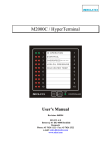
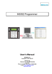
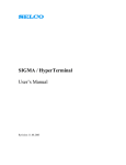
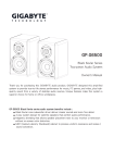
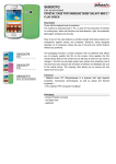
SIGMA S6500 UI Module
User’s Manual
Revision: 31.08.2006
Firmware: 050210
SELCO A/S
Betonvej 10 - DK-4000 Roskilde
Denmark
Phone: 45 7026 1122 - Fax: 45 7026 2522
e-mail: [email protected]
Web site: www.selco.com
SELCO A/S
SIGMA S6500 UI Module
Table of Contents
1
Preface..........................................................................................................................................3
2
System Preparation ......................................................................................................................4
2.1
3
Installation....................................................................................................................................5
3.1
4
Setting the CAN bus address ...............................................................................................4
Dimensions ..........................................................................................................................6
Terminals .....................................................................................................................................7
4.1
Power Supply .......................................................................................................................8
4.1.1 Primary Supply ................................................................................................................8
4.1.2 Backup Supply .................................................................................................................8
4.2
CAN BUS ............................................................................................................................8
5
4.3
Alarm ...................................................................................................................................8
4.4
I/O ........................................................................................................................................8
Specifications ...............................................................................................................................9
Revision: 31.08.2006
Page 2 of 9
SELCO A/S
SIGMA S6500 UI Module
1 Preface
The SELCO Sigma S6500 UI module can be used to configure the SELCO Sigma S6000 IO/P and
S/LS modules. The UI module will access the configuration parameters stored in the IO/P and S/LS
module and present these parameters to the operator in a user-friendly and easy accessible menu
structure. Furthermore the UI module functions as a digital multi-meter, providing information
about voltages, currents, load levels, power factor etc.
Revision: 31.08.2006
Page 3 of 9
SELCO A/S
SIGMA S6500 UI Module
2 System Preparation
2.1 Setting the CAN bus address
The 4-point dip-switch located on the rear side of the S6500 is used to set the CAN bus address of
the module. The CAN bus address is set as a binary value by 4 ON/OFF switches. Valid CAN bus
address are 1 to 15.
The S6500 can be set to any address in the range 1 to 15, however it’s typically most practical to set
it to number 1.
The binary system works on the principle described below.
•
Switch 1 represents the decimal value 1
•
Switch 2 represents the decimal value 2
•
Switch 3 represents the decimal value 4
•
Switch 4 represents the decimal value 8
As an example, the address 1 is assigned by setting switch 1 to ON and the remaining switches to
OFF. Address 10 is assigned by setting switch 2 and 4 to ON and switch 1 and 3 to OFF. The
decimal value corresponds to the sum of the values ON switch values.
Revision: 31.08.2006
Page 4 of 9
SELCO A/S
SIGMA S6500 UI Module
3 Installation
The S6500 is designed for flush mounting. Outside dimensions are H x W x D = 144 x 144 x
70mm. A cut out with dimensions H x W = 138 x 138mm must be made in order to install the unit
in the switchboard cabinet.
Make sure that there is enough space in the switch board cabinet behind the unit to install the plugin connectors and the cables. An installation depth of between 50 and 70mm is recommended.
The S6500 is secured to the switch board plate through the use of the 4 mounting/fixing brackets
included in the package.
Install the S6500 as described below.
• Find a location in the switch board cabinet with enough installation depth to house the M3000
unit. Make sure that the selected location is also satisfactory from the operator’s point of view.
• Keep in mind that it may be convenient to make room for the RS232 connection if you plan to do
external programming from a PC in the future.
• Make a cut out with the dimensions H x W = 138 x 138mm in the cabinet plate.
• Remove all the plug-in connectors located at the rear side of the unit.
• Make sure the rubber gasket is in place behind the unit front plate. This gasket is necessary to
ensure compliance with the IP54 requirements.
• Insert the unit into the cut out.
• Place the 4 mounting/fixing brackets in the small rectangular cut outs located at the top and
bottom plates of the unit.
• Tighten the 4 mounting/fixing brackets with a screwdriver until the unit is firmly seated.
Be careful not to make the connection cables too short. Extending the length of all cables with
around 100mm will ease any later service task.
A twisted-pair cable must be used for the CAN bus connection. The twisted-pair cable should at
least have 4 cords (twisted 2 by 2). An outer shield is also advantageous, especially is the cable is
long or if the environment contains excessive levels of electro-magnetic interference. The shield can
be left unconnected and is only to be used if problem occur.
Terminals 2 and 4 of the CAN connector must share one set of twisted-pair wires. The GND and
connection can use one of the wires within the remaining twisted-pair set. Also note that 150 ohm
termination resistors are to be attached at each end of the CAN bus cable. The termination resistors
must be attached between the previously mentioned terminal sets, directly on the plug-in connector.
Revision: 31.08.2006
Page 5 of 9
SELCO A/S
SIGMA S6500 UI Module
3.1 Dimensions
144mm
35mm
Cut out 138 x 138mm
4.5mm
144
mm
Revision: 31.08.2006
Page 6 of 9
SELCO A/S
SIGMA S6500 UI Module
4 Terminals
Revision: 31.08.2006
Page 7 of 9
SELCO A/S
SIGMA S6500 UI Module
4.1 Power Supply
The module is equipped with two separate power supplies. Each supply works on a nominal voltage
of +24 VDC. The primary supply is fully isolated from the backup supply and vice versa. Both
supplies are isolated from the remaining circuit of the module. The dual power supply system is
provided for safety reasons and true redundancy is only obtained if each supply is powered by an
independent source. The module is capable of operating on either one of the two supplies; however
loss or failure of either the primary or the backup supply will cause the alarm relay to de-energize.
4.1.1 Primary Supply
The primary power source (e.g. the switch board +24 VDC supply) connects to terminal 1 and 2.
Terminal 1 is positive and terminal 2 is the negative reference of the primary supply. The negative
reference is not connected to the common reference of the module (GND), as this would disrupt the
isolation of the supply circuitry. The LED marked PRIMARY SUPPLY will illuminate green (steady
light) when the supply source is live and the voltage level is within limits.
4.1.2 Backup Supply
The backup power source (e.g. a +24 VDC battery backup) connects to terminal 3 and 4. Terminal
3 is positive and terminal 4 is the negative reference of the backup supply. The negative reference is
not connected to the common reference of the module (GND), as this would disrupt the isolation of
the supply circuitry. The LED marked BACKUP SUPPLY will illuminate green (steady light) when
the supply source is live and the voltage level is within limits.
4.2 CAN BUS
The CAN bus is used for high speed communication of measured and calculated parameters
between all IO/P, S/LS and UI modules within the system. Only terminal 1, 2 and 4 are used.
Connection of the GND connection on terminal 1 is required. Terminal 1 is connected to the
common reference of the module (GND). Data signal CAN L (Low) of the CAN bus interface
connects to terminal 2, while CAN H (High) connects to terminal 4. A termination resistor of 150
ohm must be connected between CAN L and CAN H (terminal 2 and 4) at each end of the cable.
Wires for CAN L and CAN H must be twisted (twisted-pair).
4.3 Alarm
The Relay Contacts plug-in connector includes an alarm change-over relay. The alarm relay
occupies terminal 1, 2 and 3. For safety reasons, the alarm relay is always normally energized. This
is to ensure that e.g. an external siren is activated if the module loses both supplies (requires that the
siren is powered from a totally independent source). The relay contact connects terminal 2 and 3
when energized and terminal 2 and 1 when de-energized. The ALARM LED ignites (at steady light)
when the module does not operate as intended.
4.4 I/O
The I/O signals are reserved for later use.
Revision: 31.08.2006
Page 8 of 9
SELCO A/S
SIGMA S6500 UI Module
5 Specifications
Primary Supply:
Backup Supply:
Display:
Dimming:
CAN Bus
Connection
Protocol:
RS232
Connection:
Function:
Protocol:
Baud rate:
Parity:
Data bits:
Stop bits:
EMC / EMI tests:
Marine tests:
Connections:
Dust and Water protection:
Dimensions:
Weight:
Fixation:
+24 V DC (-30 % / +30 %) Isolated
+24 V DC (-30 % / +30 %) Isolated
4 x 20 Characters (backlit)
LEDs and Display backlit
5 steps by depressing TEST button or by RS232 command
Screw terminals, 2-wire with GND (limp back function)
CANOpen derivative
Customized plug, 4-wire (non-isolated)
Configuration, Debugging or firmware update
ANSI terminal
1200, 2400, 4800, 9600 or 19200 baud
None, even or odd
7 or 8
1 or 2
EN 50081-2:1993 (Generic: Residential, commercial & light
industry)
EN 50263:1999 (Product: Measuring relays and protection
equipment)
EN 60945:1997 (Marine: Navigation and radio comm. equipment
and systems)
IACS E10:1997 (IACS unified environmental test specification)
Plug-in screw terminals (spring terminals available as option)
IP54 at front
144 x 144 x 35 mm (H x W x D)
cut out 138 x 138 mm.
850 g
Flush mount (4 mounting brackets)
The specifications are subject to change without notice.
Revision: 31.08.2006
Page 9 of 9