1
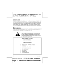
VHF FM EXCITER/TRANSMITTER
MOD. EB 30
30 WATT
USER’S MANUAL
Release 1.0
IMPORTANT NOTE : Refer to the unit’s label for your model .
Model :
Description
M2 SYSTEM EUROPE
EB 30E
VHF FM transmitter without integrated Stereo Encoder, set to 230V,
MPX input or MONO with pre-emphasis switchable to 50? sec or 75? sec.
EB 30ES
VHF FM transmitter with integrated Stereo Encoder, set to 230V.
MPX input or MONO with pre-emphasis switchable to 50? sec or 75? sec.
EB 30U
VHF FM transmitter without integrated Stereo Encoder, set to 115V.
MPX input or MONO with pre-emphasis switchable to 50? sec or 75? sec.
EB 30US
VHF FM transmitter with integrated Stereo Encoder, set to 115V.
MPX input or MONO with pre-emphasis switchable to 50? sec or 75? sec.
CAUTION: TO REDUCE THE RISK OF ELECTRICAL SHOCK, DO NOT REMOVE COVER (OR BACK).
NO USER SEVICEABLE PARTS INSIDE. REFER SERVICING TO QUALIFIED PERSONNEL.
WARNING: TO REDUCE THE RISK OF FIRE OR ELECTRICAL SHOCK DO NOT THIS APPLIANCE TO
RAIN OR MOISTURE.
THIS SYMBOL, WHEREVER IT APPEARS, ALERTS YOU TO THE PRESENCE OF UNINSULATED
DANGEROUS VOLTAGE INSIDE THE ENCLOSURE .
VOLTAGE THAT BE SUFFICIENT TO CONSTITUTE A RISK OF SHOCK.
THIS SYMBOL, WHEREVER IT APPEARS, ALERTS YOU TO IMPORTANT OPERATING AND
MAINTENANCE INSTRUCTIONS IN THE ACCOMPAYNING LITERATURE.
READ THE MANUAL.
INDEX
GENERAL DESCRIPTION .............................................................................................................................................................4
VHF FM TRANSMITTER - USER’S MANUAL
2
M2 SYSTEM EUROPE
TECHNICAL FEATURES ................................................................................................................................................................5
FRONT PANEL .....................................................................................................................................................................................6
REAR PANEL........................................................................................................................................................................................6
TOP VIEW ..............................................................................................................................................................................................7
TECHNICAL SPECIFICATION....................................................................................................................................................8
INSTALLATION AND USE.......................................................................................................................................................... 10
FREQUENCY SETTING.................................................................................................................................................................. 11
LOGO SETTING ................................................................................................................................................................................ 12
PASSWORD SETTING .................................................................................................................................................................... 13
MODULATION ADJUSTMENT................................................................................................................................................. 14
MONO OPERATION ........................................................................................................................................................................ 14
MPX OPERATION ............................................................................................................................................................................ 15
STEREOCODER OPERATION .................................................................................................................................................. 16
SCA OPERATION ............................................................................................................................................................................. 16
POWER SUPPLY BOARD............................................................................................................................................................ 17
GENERAL DESCRIPTION .......................................................................................................................................................... 17
POWER SUPPLY – RECTIFIER ELECTRICAL SCHEMATIC............................................................................................ 18
POWER SUPPLY – RECTIFIER COMPONENT LAYOUT ................................................................................................... 19
POWER SUPPLY – RECTIFIER PART S LIST.......................................................................................................................... 20
POWER SUPPLY SWITCHING MODE ELECTRICAL SCHEMATIC.............................................................................. 21
POWER SUPPLY SWITCHING MODE ELECTRICAL SCHEMATIC................................................................................ 22
POWER SUPPLY SWITCHING MODE PARTS LIST ............................................................................................................. 23
PLL SYNTESIZER MODULATION BOARD ........................................................................................................................ 24
GENERAL DESCRIPTION .......................................................................................................................................................... 24
PLL SYNT GENERAL ELECTRICAL SCHEMATIC............................................................................................................... 25
LF STAGE ELECTRICAL SCHEMATIC..................................................................................................................................... 26
PLL SYNTESIS COMPONENT LAYOUT .................................................................................................................................. 27
PLL SYNTESIS PARTS LIST ......................................................................................................................................................... 28
INPUT STAGE ELECTRICAL SCHEMATIC .......................................................................................................................... 29
INPUT STAGE COMPONENT LAYOUT ................................................................................................................................. 30
VHF FM TRANSMITTER - USER’S MANUAL
3
M2 SYSTEM EUROPE
INPUT STAGE PARTS LIST ........................................................................................................................................................ 32
MICROPROCESSOR AND CONTROL BOARD .................................................................................................................. 32
GENERAL DESCRIPTION .......................................................................................................................................................... 33
CPU AND CONTROL BOARD GENERAL ELECTRICAL SCHEMATIC ......................................................................... 33
CPU STAGE ELECTRICAL SCHEMATIC ................................................................................................................................. 34
VU-METER STAGE ELECT RICAL SCHEMATIC ................................................................................................................... 35
PROTECTION STAGE ELECTRICAL SCHEMATIC.............................................................................................................. 37
CPU AND CONTROL COMPONENT LAYOUT....................................................................................................................... 38
CPU AND CONTROL BOARD PARTS LIST............................................................................................................................. 39
30W AMPLIFIER BOARD............................................................................................................................................................ 40
GENERAL DESCRIPTION .......................................................................................................................................................... 41
30W AMPLIFIER ELECTRICAL SCHEMATIC....................................................................................................................... 41
LOW-PASS FILTER ELECTRICAL SCHEMATIC................................................................................................................... 42
POWER ADJ ELECTRICAL SCHEMATIC ................................................................................................................................ 43
30W AMPLIFIER AND LOW-PASS FILTER COMPONENT LAYOUT............................................................................. 44
POWER ADJ COMPONENT LAYOUT ....................................................................................................................................... 45
30W AMPLIFIER PARTS LIST...................................................................................................................................................... 46
LOW-PASS FILTER PARTS LIST ................................................................................................................................................ 47
POWER ADJ PARTS LIST .............................................................................................................................................................. 48
XLR AUDIO CONNECTOR PINOUTS........................................................................................................................................ 49
GUARANTEE.................................................................................................................................................................................... 50
EB 30 VHF FM TRANSMITTER
GENERAL DESCRIPTION
VHF FM TRANSMITTER - USER’S MANUAL
4
M2 SYSTEM EUROPE
The EB 30 is a direct-synthesis VHF FM transmitter and the output power is continuos
variable 0? 30 W adjustable by external control.
The output frequency range is 87.5 – 108 Mhz with 10 Khz step microprocessor
controlled with front panel LCD visualisation and setting.
A led displays when the PLL is locked and this lock control circuit inhibits the power
on the output when the transmitter is on the right frequency .
For security reasons a pre-programmed factory password is present and it is possible in
the LCD to set the name in two line for identification, to change the modality MPX,
MONO 50? sec or 75? sec or internal Stereo Encoder.
A MONO input is complete with 15 Khz low-pass audio filter.
The version /30S option is characterised by an internal Digital Stereo Encoder card.
Output frequency is phase-locked to a temperature-compensated crystal oscillator for
precision and stability.
An internal deviation limiter controls the maximum frequency deviation avoiding over
modulation.
In the EB 30 a protection for load mismatching (VSWR) is present and the alarm signal
is displayed by front panel led. A push button (Reset) resets this protection.
A temperature sensor controls the output power in case of high internal or ambient heat.
The accurate metering front panel bar with led indicators allows the parameters of
operating conditions: output power, reflected power, frequency deviation.
The input Left and Right channel are verified when you have set the mode Stereo
Encoder.
In this special quick Vu-meter with peak memory it is possible to set perfectly a
deviation level, moreover, when the audio signal is low or not present, an automatic x10
level function helps the adjustment of sub carrier .
Rear panel adjustment, output power setting (RF OUT ADJ), frequency deviation
(MPX ADJ), Left and Right ADJ are the operations that can be performed.
A 30W broadband output stage of high efficiency through the use of VHF power
MOSFETs is present.
A low-pass filter reduces at the minimum harmonics spurious in accordance with
international requirements.
The completely internal modular construction simplifies eventually maintenance or
repair.
Switching-mode power supply reduces the internal dissipation and power consumption.
TECNICHAL FEATURES
VHF FM TRANSMITTER - USER’S MANUAL
5
M2 SYSTEM EUROPE
EB 30 FRONT PANEL
EB 30 REAR PANEL
VHF FM TRANSMITTER - USER’S MANUAL
6
M2 SYSTEM EUROPE
EB 30 TOP VIEW
VHF FM TRANSMITTER - USER’S MANUAL
7
M2 SYSTEM EUROPE
TECHNICAL SPECIFICATION
RF output
Frequency range :
Frequency stabilisation:
Class of emission:
Synthesis step:
Frequency stability:
Frequency drift:
Output impedance:
Output connector:
Output power:
VSWR:
Monitor output:
Monitor output connector:
Harmonics:
Spurious:
87.5 ? 108 MHz
synthesizer with PLL
FM F3E(f3)
10 KHz
<200 Hz
? ? 200Hz(after 3 months)
50?
N female , unbalanced, rear panel
0 to 30W adjustable
? 2 at full power (30W)
? -50 dB of carrier
BNC female, unbalanced, rear panel
? -65dB
? -80dB
Transmission characteristics
Mono operation
Input level:
Input impedance:
Input connector:
Bandwidth:
Attenuation of frequency ? 19KHz:
Preemphasis:
S/N ratio :
THD+N :
-3 ? +10 dBm
10 K?
BNC female, unbalanced, rear panel
20 ? 15 KHz (? 0.25 dB)
?
50/75 ? sec
? 75 dB (? 75 KHz dev. 1 KHz ,50? sec deemph.)
? 0.1% (? 75 KHz dev. 1 KHz )
MPX operation
Input level:
-3 ? +10 dBm
VHF FM TRANSMITTER - USER’S MANUAL
8
M2 SYSTEM EUROPE
Input impedance:
Input connector:
Bandwidth:
>10 K?
BNC female, unbalanced, rear panel
20 ? 100 KHz (? 0.25 dB)
Stereo operation (internal stereocoder)
L and R input level:
Input connector:
Input impedance:
Bandwidth:
Attenuation of frequency ? 19KHz:
Preemphasis:
S/N ratio :
THD+N :
Stereo crosstalk:
-3 ? +10 dBm
XLR female, balanced or unbalanced
10 K? or 600? selectable by internal link
20 ? 15 KHz (? 0.25 dB)
? 60 dB
50/75 ? sec
? 73 dB (? 75 KHz dev. 1 KHz ,50? sec deemph.)
? 0.1% (? 75 KHz dev. 1 KHz )
? -50 dB
Supplementary signal
SCA input
Input impedance:
Input connector:
1 K?
BNC female, unbalanced, rear panel
General data
Temperature range:
Operating temperature range:
AC supply:
Consumption:
Cooling system:
Humidity:
0 to 40° C
-10 to + 45° C
115/230 V ? 10% 50/60 Hz
70VA @ 30 Wout
air forced, 24DC fan
95% max.
Dimension (W x H x D), weight
19” 1U, 482 mm x 44 mm x 440 mm , 8 Kg
VHF FM TRANSMITTER - USER’S MANUAL
9
M2 SYSTEM EUROPE
INSTALLATION AND USE
Before proceeding with the installation it is important to control if the main voltage
corresponds to the factory set.
Install the transmitter in a aerated, dry environment, with 10 to 35 °C temperature range.
Connect an antenna or a dummy load to the RF out connector in the rear panel, utilising
a 50 ohm cable type with N connector. A cable RG213 type is suitable.
Operation without antenna or with a faulty connection cable may cause a possible
breaking or degradation of the final amplifier.
Connect an audio source with appropriate connector and a cable to obtain the best result
and hi-fi quality on a long term basis.
Check out that the main on/off switch on the rear panel is in off position.
Control that the output power is at the minimum level.
Connect the transmitter to the main power supply using the cord on issue.
Switch on the transmitter: on the front panel you will see the LCD display lighted, the
led “DEV” light on and few seconds later the “LOCK” led on too.
If the set frequency is wrong, proceed as explained in Chapter “Frequency setting”.
Look at the front panel meter selecting “FWD” measure through the “SEL” pushbutton,
then adjust the output power by means of the rear panel trimmer.
Pressing the up/down button, a pre-set logo will be displayed: in order to change the
logo please refer to chapter “Logo setting”.
For security reasons, a password to proceed with the setting operations can be included;
a pre-set password is already included by the factory and can be set on or off as
explained in chapter “Password setting”. The password is different for any transmitter
produced and it is composed by n. 5 number.
VHF FM TRANSMITTER - USER’S MANUAL
10
M2 SYSTEM EUROPE
FREQUENCY SETTING
Switch the transmitter off through the on/off main switch on the rear panel; keeping the
“SEL” button pressed, switch the transmitter on; in the LCD display
MODE SETUP
STEREOCODER
will be showed; through the up/down arrows select the transmission mode,
”STEREOCODER, MPX, MONO PRE 50uS, MONO PRE 75uS
MODE SETUP
MPX
and confirm through the “SET” pushbutton; in the frontal display
100.00 MHz
Frequency Setup
will be showed; by pressing the up/down arrows select the required frequency. Please
note that keeping the up/down arrows pressed the frequency steps will change quickly.
Confirm through the “SET” pushbutton.
VHF FM TRANSMITTER - USER’S MANUAL
11
M2 SYSTEM EUROPE
LOGO SETTING
Switch the transmitter off through the on/off main switch on the rear panel; keeping the
up and the down arrows pressed simultaneously, switch the transmitter on; in the LCD
display
FIRST ROW
SOFRATEC FRANCE
will be showed; through the up/down arrow buttons change the alphanumeric
characters, confirm with “SEL” button and step to the next character; once completed
the row, confirming with “SEL” button, in the LCD display
SECOND ROW
BROADCAST
will be showed; proceed as above indicated for the first row.
The complete logo is
SOFRATEC
FM EXCITER
VHF FM TRANSMITTER - USER’S MANUAL
12
M2 SYSTEM EUROPE
PASSWORD SETTING
Switch the transmitter off through the on/off main switch on the rear panel; keeping the
“SEL” and “SET” pushbuttons pressed simultaneously, switch the transmitter on.
In the LCD display
Password
0
will be showed. Through the up/down arrows select the first number, confirm with the
“SET” button and step to the next number.
Password
02468
Once completed the operation, if the password is correct, switching the transmitter on in
setup mode the system will ask for the password; without the correct password (2nd
password number) the setup mode cannot be selected. In order to disable the password,
repeat he above explained procedure, selecting the first password on issue by the
customer. The next setup procedure will not require the password.
VHF FM TRANSMITTER - USER’S MANUAL
13
M2 SYSTEM EUROPE
MODULATION ADJUSTMENT
Mono operation
Switch the transmitter off through the on/off main switch on the rear panel; keeping the
“SEL” button pressed, switch the transmitter on; in the LCD display
MODE SETUP
STEREOCODER
will be showed; through the up/down arrows select the transmission MONO PRE 50uS
or MONO PRE 75uS
MODE SETUP
MONO PRE 50uS
and confirm through the “SET” pushbutton; in the frontal display “frequency setup”
will be showed ,by pressing the up/down arrows select the required frequency.
Apply a Mono signal in the input BNC connector on the rear panel ( 10K? input
impedance emphasised ) and select “DEV” measure through the “SEL” pushbutton.
Look at the front panel meter and adjust the deviation level by means of the rear panel
trimmer “input adj” .
When modulation is ? 75KHz they light on leds green. Lighting of an or more leds led, it
involves a over-modulation.
For a accurate measure, the first red led, when it light on, it remains memorised for a
little of time.
VHF FM TRANSMITTER - USER’S MANUAL
14
M2 SYSTEM EUROPE
Mpx operation
Switch the transmitter off through the on/off main switch on the rear panel; keeping the
“SEL” button pressed, switch the transmitter on; in the LCD display
MODE SETUP
STEREOCODER
will be showed; through the up/down arrows select the transmission MPX
MODE SETUP
MPX
and confirm through the “SET” pushbutton; in the frontal display “frequency setup”
will be showed ,by pressing the up/down arrows select the required frequency.
Apply a MPX signal in the input BNC connector on the rear panel ( 10K? input
impedance) and select “DEV” measure through the “SEL” pushbutton.
Look at the front panel meter and adjust the deviation level by means of the rear panel
trimmer “input adj” .
When modulation is ? 75KHz they light on leds green. Lighting of an or more leds led, it
involves a over-modulation.
For a accurate measure, the first red led, when it light on, it remains memorised for a
little of time.
VHF FM TRANSMITTER - USER’S MANUAL
15
M2 SYSTEM EUROPE
Stereocoder operation (with internal card)
Switch the transmitter off through the on/off main switch on the rear panel; keeping the
“SEL” button pressed, switch the transmitter on; in the LCD display
MODE SETUP
STEREOCODER
will be showed; through the up/down arrows select the transmission STEREOCODER
and confirm through the “SET” pushbutton; in the frontal display “frequency setup”
will be showed ,by pressing the up/down arrows select the required frequency.
Apply a Left and Right signal in the corresponding female XLR connectors on the rear
panel
( 10K? input impedance) and select “L” measure through the “SEL”
pushbutton. Look at the front panel meter and adjust the input stereocoder level by
means of the rear panel trimmer “Left adj.” .
Select “R” measure through the “SEL” pushbutton and look at the front panel meter;
adjust the input stereocoder level by means of the rear panel trimmer “Right adj.” .
At this time select “DEV” measure through the “SEL” pushbutton.
Look at the front panel meter and adjust the deviation level by means of the rear panel
trimmer “input adj.”. When modulation is ? 75KHz green leds are on. One or more red
leds on means an over-modulation.
For an accurate measure, the first red led, when on, remains memorised for a little time.
At this point level of sub carrier at 19KHz can be checked. Set at zero audio levels of
left and right input; automatically, after a few seconds, the Vu-meter sets in X10 and the
right red led turns on.
Measure now the level to have 0dB, corresponding to the 10% of modulation.
SCA operation
VHF FM TRANSMITTER - USER’S MANUAL
16
M2 SYSTEM EUROPE
For SCA signal (>53 KHz), use the input BNC connectors ( 1 K? input impedance).
The SCA input level, for a correct deviation of the main carrier (? 1.25KHz peak), is
about 0.3 Vpp.
POWER SUPPLY BOARD
GENERAL DESCRIPTION
The power supply of the transmitter is composed of more parts:
?? Toroidal transformer
?? Two rectifier bridge and capacitor filter card
?? Switching-mode control card
A toroidal transformer reduces a main voltage for the “rectifier and capacitor card”.
This transformer has two secondary voltage outputs and precisely 31Vac and 15Vac.
A rectifier bridge card rectifies and levels the voltage for the “switching-mode card”.
The efficiency in this power supply is higher than 85% and the voltage output are
constant even in case of wide mains fluctuations (? 10%).
This power supply gives +28VDC to the power amplifier, +24VDC to the fan,
+12VDC/-12VDC to the synthesizer card, the stereocoder card and the vu-meter card,
+5VDC to the microprocessor card and the LCD display.
VHF FM TRANSMITTER - USER’S MANUAL
17
M2 SYSTEM EUROPE
POWER SUPPLY – RECTIFIER ELECTRICAL SCHEMATIC
VHF FM TRANSMITTER - USER’S MANUAL
18
M2 SYSTEM EUROPE
POWER SUPPLY – RECTIFIER COMPONENT LAYOUT
VHF FM TRANSMITTER - USER’S MANUAL
19
M2 SYSTEM EUROPE
POWER SUPPLY – RECTIFIER PARTS LIST
PART
USED
DESCRIPTION
COMPONENT IDENTIFIER
______________________________________________________________________
1
2
3
4
5
1
1
5
1
1
RECT.BRIDGE 1A
RECT.BRIDGE 6A
1000uF 50V
CONNECTOR
CONNECTOR
PD1
PD2
C139 C140 C141 C142 C143
J27
J26
VHF FM TRANSMITTER - USER’S MANUAL
20
M2 SYSTEM EUROPE
POWER SUPPLY SWITCHING MODE ELECTRICAL SCHEMATIC
VHF FM TRANSMITTER - USER’S MANUAL
21
M2 SYSTEM EUROPE
POWER SUPPLY – SWITCHING MODE COMPONENT LAYOUT
VHF FM TRANSMITTER - USER’S MANUAL
22
M2 SYSTEM EUROPE
POWER SUPPLY – SWITCHING MODE PARTS LIST
PART
USED
DESCRIPTION
COMPONENT IDENTIFIER
______________________________________________________________________
1
2
1
2
PIN
1K
+28V
R246 R247
VHF FM TRANSMITTER - USER’S MANUAL
23
M2 SYSTEM EUROPE
3
4
5
6
7
8
9
10
11
12
13
14
15
16
17
18
19
20
21
2
1
2
1
1
4
2
1
1
1
1
2
2
1
1
2
1
1
1
1N5122
4.7K
5K
18K
100n
100uF
100uH
120uH
22 ohm 2W
330uH
470uF
470uF
470uF
PIN
CONNECTOR
CI LM2576HV-ADJ
CI LM7805
CI LM7912
CONNECTOR
D23 D24
R251
R249 R250
R248
C144
C145 C146 C147 C148
L22 L24
L21
R252
L23
C149
C150 C151
C152 C153
GND
J28
IC27 IC28
IC29
IC30
J29
PLL SYNTESIZER MODULATION BOARD
GENERAL DESCRIPTION
The synthesiser modulation board is a classical PLL circuit with 10KHz step across the
entire FM band. The fundamental frequency VCO, PLL integrated circuit and any RF
VHF FM TRANSMITTER - USER’S MANUAL
24
M2 SYSTEM EUROPE
parts are inside in a proprietary PLL synthetiser module; the RF out is present in J1
connector.
This PLL circuit is controlled by microprocessor for frequency setting and it is
modulated by LF stage that accepts a composite stereo (MPX), mono and SCA signals.
The mono input level is calibrated by R76 trimmer, pre-emphasised with 50 or 75? sec,
filtered by elliptic filter with a flat response (20 to 15KHz ? 0.25dB) and it has an out
band attenuation ? 50dB for frequency greater than 19 Khz. The mono audio signal is
present in a IC5B sum amplifier but when it is not utilised, it is switched off by IC6C.
The composite stereo signal and the SCA sub-carrier are always summed in the IC5B
but when they are not utilised, they are switched off by IC6D and IC6B.
Before the VCO stage, there is an adjustable and selectable (jumper JP1) deviation
limiter that prevents the over-modulation .
PLL SYNT. GENERAL ELECTRICAL SCHEMATIC
VHF FM TRANSMITTER - USER’S MANUAL
25
M2 SYSTEM EUROPE
LF STAGE ELECTRICAL SCHEMATIC
VHF FM TRANSMITTER - USER’S MANUAL
26
M2 SYSTEM EUROPE
PLL SYNTHESIS COMPONENT LAYOUT
VHF FM TRANSMITTER - USER’S MANUAL
27
M2 SYSTEM EUROPE
PLL SYNTHESIS PARTS LIST
VHF FM TRANSMITTER - USER’S MANUAL
28
M2 SYSTEM EUROPE
PART
USED
DESCRIPTION
COMPONENT IDENTIFIER
______________________________________________________________________
1
2
3
4
5
6
7
8
9
10
11
12
13
14
15
16
17
18
19
20
21
22
23
2
4
1
1
1
1
1
2
2
1
2
3
7
1
1
5
2
1
1
2
2
2
10
1.2n
1K
1N4148
1uF
2.2n
3.3n
4.7K
4.7n
4.7p
5.6K
ZENER 5.6V
6.8uH
10K
10n
15K
22K
27K
33K
47K
47mH
47uF
100K
100n
24
25
26
27
28
29
30
31
32
33
34
35
36
37
38
39
40
3
2
1
1
1
1
2
1
1
1
1
2
2
1
1
1
1
100p
220 ohm
220p
330K
390p
IC CD4066
SCHOTTKY
JUMPER
CONNECTOR
CONNECTOR
IC LM358
IC LM833
10K TRIMMER
SMB CONNECTOR
4MHz
CAP VAR 22p
1M
C63 C64
R60 R61 R62 R63
D2
C77
C68
C67
R78
C58 C59
C61 C62
R64
DZ2 DZ3
L4 L5 L6
R65 R66 R67 R68 R69
C60
R54
R70 R71 R72 R75 R81
R73 R80
R55
R57
L7 L8
C69 C70
R56 R79
C52 C55 C56 C57 C71
C72 C73 C74 C75 C76
C49 C50 C51
R58 R59
C65
R74
C66
IC6
D3 D4
JP1
J2
J3
IC7
IC4 IC5
R76 R77
J1
X1
C48
R35
INPUT STAGE ELECTRICAL SCHEMATIC
VHF FM TRANSMITTER - USER’S MANUAL
29
M2 SYSTEM EUROPE
INPUT STAGE COMPONENT LAYOUT
VHF FM TRANSMITTER - USER’S MANUAL
30
M2 SYSTEM EUROPE
VHF FM TRANSMITTER - USER’S MANUAL
31
M2 SYSTEM EUROPE
INPUT STAGE PARTS LIST
PART
USED
DESCRIPTION
COMPONENT IDENTIFIER
______________________________________________________________________
1
2
3
4
5
6
7
8
3
1
1
1
1
1
1
1
10K TRIMMER
CONNECTOR
CONNECTOR
XLR CONNECTOR
BNC CONNECTOR
BNC CONNECTOR
XLR CONNECTOR
BNC CONNECTOR
R241 R242 R243
J25
J19
J20
J23
J22
J21
J24
MICROPROCESSOR AND CONTROL BOARD
VHF FM TRANSMITTER - USER’S MANUAL
32
M2 SYSTEM EUROPE
GENERAL DESCRIPTION
The microprocessor and control board is a circuit that contains the CPU, the push
button for setting, the led vu-meter for analog measurement and the resetable protection
for SWR.
The CPU, a 8bit with an internal memory flash, controls the LCD display, the PLL
frequency and all the control functions.
The alphanumeric display is a separate module, connected to the board by a small flat
cable. The internal board trimmer R148 regulates the LCD contrast. A power supply for
the backlight leds is provided by J9.
The led vu-meter is a separate circuit and controls the level of direct and reflected
power and the level of deviation too.
The internal trimmer for the regulation of level deviation is R191, for the regulation of
X10 level is R186, for the regulation of direct power level is R244, for the regulation of
reflected power level is R215 (set to obtain the maximum possible level of SWR at 0
dB).
The protection circuit is a calibrated circuit with regulation threshold by R210 trimmer.
When a VSWR level exceeds the pre-setting threshold, this protection sets the power
output at the minimum.
The power supply of this card is connected through the J8 connector.
CPU AND CONTROL BOARD GENERAL ELECTRICAL SCHEMATIC
VHF FM TRANSMITTER - USER’S MANUAL
33
M2 SYSTEM EUROPE
CPU STAGE ELECTRICAL SCHEMATIC
VHF FM TRANSMITTER - USER’S MANUAL
34
M2 SYSTEM EUROPE
VU-METER STAGE ELECTRICAL SCHEMATIC
VHF FM TRANSMITTER - USER’S MANUAL
35
M2 SYSTEM EUROPE
VHF FM TRANSMITTER - USER’S MANUAL
36
M2 SYSTEM EUROPE
PROTECTION STAGE ELECTRICAL SCHEMATIC
VHF FM TRANSMITTER - USER’S MANUAL
37
M2 SYSTEM EUROPE
CPU AND CONTROL COMPONENT LAYOUT
VHF FM TRANSMITTER - USER’S MANUAL
38
M2 SYSTEM EUROPE
CPU AND CONTROL BOARD PARTS LIST
PART
USED
DESCRIPTION
COMPONENT IDENTIFIER
______________________________________________________________________
1
2
6
29
LED
1.5K
3
9
1K
4
14
1N4148
5
6
7
1
1
8
1n
1uF
2.2K
8
9
10
11
12
13
14
15
16
1
3
2
1
1
2
1
2
27
2K TRIMMER
4.7K
4.7p
4MHz
5.6K
ZENER 5.6V
8.2K
10 ohm
10K
17
18
1
8
10n
10uF
19
20
21
22
23
24
25
26
27
28
29
1
1
2
2
2
1
5
1
1
3
8
22 ohm
22K
22M
27K
27pF
33K
47K
50K TRIMMER
68K
IC 74HC374
100K
30
11
100n
31
28
270 ohm
DL1 DL2 DL3 DL4 DL5 DL6
R115 R116 R117 R118 R119
R120 R121 R122 R123 R124
R125 R126 R127 R128 R129
R130 R131 R132 R133 R134
R135 R136 R137 R138 R139
R140 R141 R142 R143
R87 R88 R89 R91 R99 R100
R101 R102 R103
D5 D6 D7 D8 D9 D10 D11 D12
D13 D14 D15 D16 D17 D18
C101
C88
R190 R199 R200 R201 R202
R203 R205 R209
R191
R150 R151 R185
C90 C91
X2
R90
DZ4 DZ5
R187
R82 R253
R92 R93 R94 R95 R96 R97 R98
R104 R106 R108 R109 R110 R111
R112 R113 R114 R192 R193 R196
R197 R198 R207 R208
C89
C94 C95 C96 C97 C98 C105 C106
C107
R211
R146
R188 R189
R144 R145
C92 C93
R206
R83 R84 R85 R194 R195
R186
R149
IC14 IC15 IC16
R105 R107 R152 R153 R154 R155
R214 R216
C78 C81 C82 C83 C84 C85 C86
C100 C102 C103 C104
R156 R157 R158 R159 R160 R161
VHF FM TRANSMITTER - USER’S MANUAL
39
M2 SYSTEM EUROPE
32
33
34
35
36
37
38
39
40
41
42
43
44
46
47
48
49
50
51
52
53
54
55
56
57
2
2
1
1
2
1
1
1
1
1
3
1
1
1
3
7
1
1
1
1
5
1
2
1
4
330 ohm
330K
330p
470K
IC CD4066
IC CD4093
4.7K
CONNECTOR
IC AT90S2313-C
BC546
BC846
BC857
CONNECTOR
CONNECTOR
LED-BAR
IC LM339-B
IC LM358
LED
IC NE555
CONNECTOR
PB
CONNECTOR
IC TL084
IC ULN2003
10K TRIMMER
R162 R163 R164 R165 R166 R167
R168 R169 R170 R171 R172 R173
R174 R175 R176 R177 R178 R179
R180 R181 R182 R183
R212 R213
R147 R204
C99
R86
IC10 IC11
IC26
R184
J8
IC12
TR1
T8 T9 T10
T7
J7
J9
LB1 LB2 LB3
IC17 IC18 IC19 IC20 IC21 IC22 IC23
IC25
DL7
IC24
J6
S1 S2 S3 S4 S5
J5
IC8 IC9
IC83
R148 R210 R215 R244
30W AMPLIFIER BOARD
VHF FM TRANSMITTER - USER’S MANUAL
40
M2 SYSTEM EUROPE
GENERAL DESCRIPTION
This board is composed of three amplification stages. The first stage is realised by a
BFR93 transistor that amplifies the signal coming out from the PLL syntesizer. The
second stage is composed by a 2N3553 transistor that sets the level for the final stage.
The third and final stage is composed by D1002UK RF mosfet that brings the output
level up to 30W.
The R255 trimmer in the POWERADJ board adjusts simultaneously the supply voltage
level of first and second stage to obtain the power output regulation.
In the 30W amplifier board an on-timer with 7-8 seconds delay time is present, in order
to avoid accidental out-of-band emissions in the initial PLL locking period.
After this RF broadband amplifier there is a low-pass filter with the directional coupler;
this filter reduces the harmonic spurious and the directional coupler generates the dc
signals proportional to the direct and reflected RF power.
30W AMPLIFIER ELECTRICAL SCHEMATIC
VHF FM TRANSMITTER - USER’S MANUAL
41
M2 SYSTEM EUROPE
LOW-PASS FILTER ELECTRICAL SCHEMATIC
VHF FM TRANSMITTER - USER’S MANUAL
42
M2 SYSTEM EUROPE
POWER ADJ ELECTRICAL SCHEMATIC
VHF FM TRANSMITTER - USER’S MANUAL
43
M2 SYSTEM EUROPE
30W AMPLIFIER AND LOW-PASS FILTER COMPONENT LAYOUT
VHF FM TRANSMITTER - USER’S MANUAL
44
M2 SYSTEM EUROPE
POWER ADJ COMPONENT LAYOUT
VHF FM TRANSMITTER - USER’S MANUAL
45
M2 SYSTEM EUROPE
30W AMPLIFIER PARTS LIST
VHF FM TRANSMITTER - USER’S MANUAL
46
M2 SYSTEM EUROPE
PART
USED
DESCRIPTION
COMPONENT IDENTIFIER
______________________________________________________________________
1
2
3
4
5
6
7
8
9
10
11
12
13
14
15
16
17
18
19
20
21
22
23
24
25
26
27
28
29
30
31
32
33
34
35
36
37
38
39
40
41
5
1
1
1
2
2
5
5
1
1
1
1
1
1
2
2
2
4
1
1
3
1
4
1
1
1
1
1
1
1
1
2
1
1
1
1
1
1
1
1
1
IND
PIN
0 ohm
1.5K
1K
1N4148
1n
1nF
2N3553
3.3p
3.9K
4.7 ohm
5.6V ZENER
5.6p
10 ohm
10K
10nF
10uF
12V ZENER
22p
33p
39p
47 ohm
100 ohm
100nH
120p
150 ohm
180 ohm
220 ohm
330p
470K
560 ohm
BCP54
BFR93A
D1002UK
PIN
IC NE555
PIN
PIN
CONNECTOR SMB
VK200
L10 L11 L13 L14 L15
J12
R235
R221
R230 R233
D19 D20
C79 C80 C87 C108 C109
C123 C124 C125 C126 C127
T12
C118
R236
R245
DZ7
C129
R217 R218
R220 R234
C121 C122
C113 C114 C115 C116
DZ6
C119
C110 C111 C112
C120
R225 R227 R228 R229
R219
L9
C128
R226
R224
R232
C117
R223
R222 R231
T13
T11
T14
J13
IC13
J14
J11
J10
L12
LOW-PASS FILTER PARTS LIST
VHF FM TRANSMITTER - USER’S MANUAL
47
M2 SYSTEM EUROPE
PART
USED
DESCRIPTION
COMPONENT IDENTIFIER
______________________________________________________________________
1
2
3
4
5
6
7
8
9
10
11
12
13
2
1
4
3
1
2
1
1
1
1
1
1
5
1K
1N4148
1n
33p
39p
47 ohm
47p
SCHOTTKY
PIN
PIN
PIN
PIN
IND
R237 R238
D21
C130 C131 C132 C133
C134 C137 C138
C135
R239 R240
C136
D22
J18
J16
J15
J17
L16 L17 L18 L19 L20
POWER ADJ PARTS LIST
VHF FM TRANSMITTER - USER’S MANUAL
48
M2 SYSTEM EUROPE
PART
USED
DESCRIPTION
COMPONENT IDENTIFIER
______________________________________________________________________
1
2
3
4
5
6
7
8
9
1
1
1
1
1
1
1
1
1
PIN
1K
10K TRIMMER
PIN
PIN
PIN
PIN
PIN
CONNECTOR
P2
R254
R255
P1
P4
P5
P6
P3
J30
XLR AUDIO CONNECTOR PINOUTS
VHF FM TRANSMITTER - USER’S MANUAL
49
M2 SYSTEM EUROPE
The figure below shows how to realise the audio cable connection in balanced or
unbalanced mode.
XLR FEMALE CONNECTION
XLR PIN
1
2
3
BALANCED
UNBALANCED
GROUND
+ SIGNAL
- SIGNAL
GROUND
+ SIGNAL
GROUND
GUARANTEE
VHF FM TRANSMITTER - USER’S MANUAL
50
M2 SYSTEM EUROPE
The transmitter equipment carries a one year guarantee on all its components with the
exclusion of the final RF power mosfet, which may be damaged by faulty output
connections.
This guarantee does not cover damages due to:
?? Delivery operations
?? Non authorised maintenance and modifications
?? External causes
?? Improper use or abnormal conditions of operations
No other guarantee is expressed or implied.
During the guarantee period, M2 system Europe will, at its option, either repair or
replace products which prove to be defective. When trouble occurs, buyer should
contact his local supplier or M2 system Europe giving full details of the problem and
the model name and serial number.
For the products returned to M2 system Europe for guarantee service, shipping and
transportation charges to deliver the product to M2 system Europe as well as
transportation charges to return it back (door to door) will be at buyer’s charge.
PREMUTO; in a same time
TOUCH SEL
SET UP
CONFIRMATION SET
VHF FM TRANSMITTER - USER’S MANUAL
51