1
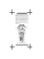
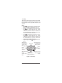
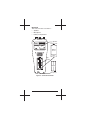
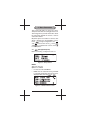
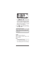
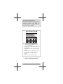
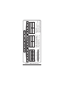
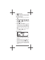
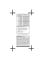
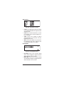
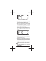
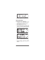
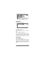
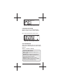
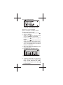
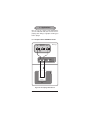
MAN-10100-001 Rev. C00
SUNRISE TELECOM
I N C O R P O R A T E D
SunLite E1
®
User’s Manual
SS265
Sunrise Telecom®...a step ahead
302 Enzo Drive San Jose, CA 95138
Tel: 1-408-363-8000 Fax: 1-408-363-8313
1
� WARNING
Using the supplied equipment in a manner not specified by Sunrise Telecom
may impair the protection provided by the
equipment.
Copyright 2004
Sunrise Telecom Incorporated
This device uses software either developed by
Sunrise or licensed by Sunrise from third parties. The software is confidential and proprietary. The software is protected by copyright and
contains trade secrets of Sunrise or Sunrise’s
licensors. The purchaser of this device agrees
that it has received a license solely to use the
software as embedded in the device, and the
purchaser is prohibited from copying, reverse
engineering, decompiling, or disassembling
the software.
2
SunLite E1
SunLite E1 User’s Manual
Table of Contents
1 General Description ............................. 5
1.1 LED Panel ........................................... 6
1.2 Keys ..................................................... 8
1.3 Connectors, Controls, and Back Side . 10
1.4 Batteries ............................................ 12
2 Basic Definitions ................................ 13
3 Menus .................................................. 14
4 Menu Parameters ................................ 15
4.1
(Configuration) Key ................... 15
4.2
(Test Pattern) Key ...................... 20
4.3
(Transmit) Key ........................... 22
4.4
(Results) Key ................................. 23
4.5
(Function) Key ........................... 33
4.6
(VF Measurements) Key ........... 48
4.7
(CAS) Key ................................. 50
4.8
(Histogram) Key ........................ 51
4.9
(Sa Bits) Key ............................. 52
5 Firmware Upgrading........................... 53
5.1 CPU Download .................................. 53
5.2 FLASH Memory Download ................ 53
5.3 DSP Download .................................. 53
6 Applications ........................................ 54
6.1 Accept a New 2.048 Mbit/s Circuit..... 54
6.2 Monitoring an In-Service Circuit ........ 55
6.3 Measuring Propagation Delay ........... 56
6.4 Frequency Synchronization ............... 57
6.5 Measuring Signal Level ..................... 58
6.6 Channel Associated Signalling .......... 59
6.7 Voice Frequency Channel Monitoring 59
68 Send/Receive Digital Tones ................ 60
6.9 N (or M) x64 kbit/s Testing ................. 61
7 Specifications ..................................... 62
8 Express Limited Warranty.................. 68
9 Declaration of Conformity ................. 71
Index ......................................................... 73
3
Important Safety Information
� WARNINGS:
• Use NiMH batteries only.
• Use SA143 or equivalent AC adaptor to
charge the NiMH batteries.
• Use only Sunrise Telecom 120-21011-120
replacement NiMH batteries
Operating Environment
This test set is intended for operation in at
least partly weather protected and temperature
controlled locations, as per IEC 721-3-7, Class
7K2. Do not operate this test set in rain, or in
a direct water splash environment.
Input Connectors
These connectors are intended for connection
to E1 circuits only.
• Maximum input voltage is 12VDC.
Dip Switch Information
The six dip switches, located in the battery
compartment (see Figure 6), are intended for
factory test and programming use. They should
be left in the positions indicated in the following
figure for normal operation.
ON
CTS
123456
Figure 1 Dip Switch
4
SunLite E1
1 General Description
Welcome to the SunLite E1. This compact,
lightweight, and versatile test set allows you to
perform many E1 tests. Accept a circuit, check
for quality, observe signalling information; the
SunLite E1 performs all of these functions
and more via a simple keypad-oriented user
interface. This manual will introduce you to the
SunLite E1. You will be led through test setup
and shown how to perform applications.
If you have questions, please call your distributor or Sunrise Telecom’s Customer Service
department.
������
��������
�����������
Figure 2 SunLite E1, Front View
5
1.1 LED Panel
Just below the LCD screen is a group of LEDs
(see Figure 3). Most of these LEDs reflect
received information. A flashing red LED indicates an error or alarm has occurred in the
past, but is no longer occurring, press
to clear.
Figure 3 LEDs
SIGNAL
• Green: Receiving E1 pulses.
• Red: Not receiving pulses.
PCM–30, PCM–31
• Green: Receiving framing as expected.
• Red: Framing expected, not received.
CRC-4
• Green: CRC-4 received as expected.
• Red: CRC-4 expected, not received.
CODE
• Red: Code error received.
SYNCH
• Green: Synchronized on received test pattern.
• Red: Synchronization has not been
achieved.
BIT
• Red: Bit error received.
ERROR
• Red: Code, bit, bitslip, CRC-4, E-bit, or
Frame error received.
6
SunLite E1
AIS
• Red: Receiving an unframed all ones signal
(Alarm Indication Signal).
RAI
• Red: Remote Alarm Indication received.
TX
• Green: Transmitting.
• Flashing green: Transmitting in self-loop
mode.
• No light: Not transmitting.
RUN
• Green: Measurements are being taken.
Power
Located to the right of the
power key.
• Red: Battery running low.
• Green: Test set is fully charged and/or
plugged into the adaptor.
7
1.2 Keys
The test set has two sets of keys. The central
set controls the most basic functions. The
lower portion controls specific functions and
actions.
Notes
• When (scroll) has been released for more
than a second, the parameters are set.
• The
cursor left/decrease key, decreases
the internal clock frequency (for clock
calibration) and the timeslot selection in
VF measurements, as well as moves the
cursor in the indicated direction.
• The
cursor right/increase key, increases
the internal clock frequency (for clock
calibration) and the timeslot selection in
VF measurements, as well as moves the
cursor in the indicated direction.
• Repeatedly pressing (stop) will have no
affect.
��������������
�������������
��������������
�����
���������
������������������
����������������
������������
�������
���������
��������
�������
��������
��������
�������������
����������������
�����
�����������������
�����������
��������������
������
�����������������
�����
Figure 4 Center Keys
8
SunLite E1
Lower group of keys
The following keys are shown in Figure 2
: Displays the configuration screen.
: Displays the test pattern screen.
: Page up through available screens.
: Displays VF measurements.
: View the Channel Associated Signalling
on the received line.
: Page down through available screens.
: Send the Loop Down code selected in the
Loop codes screen in the
menu.
: Send the Loop Up code selected in the
Loop codes screen in the
menu.
: View the status of the received Sa 4-8
bits.
: Print the screen. If viewing results or VF
measurements, all screens will be printed. In
profiles, the selected profile will be printed.
: Displays histogram screens.
: Turn the transmitter on/off, or to enter the
self-loop mode.
: Turn the backlight on/off.
: Inject an error on the transmitted signal.
: Press to clear blinking LEDs.
: Press the lock/unlock key once to lock
all keys. The test set will beep once, and its
settings cannot be changed. Press the key
twice, the keys will be unlocked, and the test
set will beep twice.
: Access the function menu to set various
parameters.
: Execute a specific action.
: Turn the test set on/off. Note that if you
quickly turn the test set on after turning it off,
you may see static for a moment. It will clear
and the normal start up screen will appear.
9
1.3 Connectors, Controls, and Back Side
This section describes the connectors and
controls available on the test set.
Top Panel
��
�������
��
�
Figure 5 SunLite E1 Top Panel
� WARNING
The connectors on this panel are intended for
connection to E1 circuits only, as defined in
EN60950. Maximum input voltage: 12VDC.
• TX: 75Ω unbalanced BNC connector;
transmits the E1 signal from the test set.
• REF CLK: BNC reference clock input connector; plug a 2.048 Mbit/s, AMI or HDB3,
reference clock signal in here.
• RX: 75Ω unbalanced BNC connector; receive the E1 signal here.
Right Side
• Volume Control: Adjusts speaker volume.
• Serial Port: This RJ-11 serial port is used to
connect a printer or download firmware.
Left Side
• Contrast Control: Adjusts screen contrast.
Bottom Side
• 5VDC: Plug the power adaptor here. The
test set may be operated with a discharged
battery, provided the charger is connected.
The battery will charge during operation.
10
SunLite E1
Back Side
This side of the test set contains :
• Speaker
• Microphone
• Battery Compartment
�������
����������
�
�����������
�
�������
�����
���������
����
���
������
�
�
ON
CTS
123456
���������
�
�
����������
Figure 6 Sunlite E1 Back View
11
1.4 Batteries
The test set’s internal batteries are accessed
through the back of the test set. Refer to Figure
6 and the following instructions on changing
the batteries.
� WARNING
Use NiMH batteries only.
Use SA143 or equivalent AC adaptor to
charge the NiMH batteries.
• Use only Sunrise Telecom 120-21011-120
replacement NiMH batteries.
•
•
Replacing the NiMH batteries
1. Remove the battery compartment cover by
pressing the Release tab towards the center
of the cover and then lift the cover off.
2. Remove the old batteries by pushing each
battery against the spring and lifting upward.
You may need a flat tool, such as a small
screw driver to accomplish this.
3. Insert the new batteries by pressing the
negative end of each battery against the
spring (as indicated in the battery compartment) and push each battery into place.
4. Replace the cover by inserting the retaining
tabs into their slots and then gently push
the cover down into place.
12
SunLite E1
2 Basic Definitions
Here are some abbreviations you will run into,
and their definitions.
AIS: Alarm Indication Signal—an all 1s signal
on the line. Indicates loss of signal or other
severe problem.
HHH: MM:SS: hours: minutes: seconds
LT: Line Termination
LVL: Level
PMP: Protected Monitoring Point
RAI: Remote Alarm Indication; notice that an
alarm has occurred at the far end of the line
UI: Unit Interval; This is the time it takes to
transmit 1 bit; .488 ms at 2.048 Mbit/s
mS: Microsecond
VF: Voice Frequency
13
3 Menus
The test set is key driven. The following table
shows the organization of the keys and their
options. To select a menu, press it’s corresponding key. If you get lost in a menu, press
the same key to start over.
Key
14
Page
15
16
19
19
Options or Screens
MODE
FRAME
INPUT
TxCLK
20
Test Patterns
22
MODE
23
24
25
28
28
29
31
32
33
33
34
34
35
36
37
38
39
39
40
40
41
42
43
43
44
44
45
45
45
46
46
47
SUMMARY
SIGNAL/FREQUENCY
ERRORS
SIGNAL ERRORS
FRAMING RAI
G.821
G.826
M.2100/550
TIME & DATE
SET IDLE CODES
PRINT PERIOD
PROFILE
TEST DURATION
TEST RESULTS
DELAY TIMER
SEND FRAME WORDS
M.2100 PARAMETERS
CLK CALIBRATION
AUDIBLE ALARM
ERROR INJECTION
LOOP CODES
ERASE NV RAM
COMPANDING
PROPAGATION DELAY
LINE CODING
FREQ. RESOLUTION
AUTO STRESS
LANGUAGE SELECTION
LINE TERMINATION
ALARM GENERATION
G.821 ALLOCATION
VIEW RECEIVED DATA
48
VF Setup and Measurements
50
Observe Channel Associated Signalling
on all 30 channels.
51
Histogram measurements
52
Observe Sa-bit status
SunLite E1
4 Menu Parameters
This section will guide you in the key, menu,
and option selections for setting up the test set.
Technology Notes provide information about
the technology behind the choices, and are
enclosed in frames.
On power up, the test set does a self test, after
which it displays the Version/Option screen.
to begin configuration. Use
,
Press
and
to move to the cursor (_). Press
and
to scroll between screens. Press
to select options.
4.1
(Configuration) Key
Before connecting, configure the test set.
Figure 7 Set Up Screen
MODE
Select the test rate.
Options: E1, Nx64k
• E1: Test at a full 2.048 Mbit/s.
• Nx64k: Test at fractional testing. If Nx64k
is selected, the timeslot selection screen is
displayed after pressing
or
.
Figure 8 PCM-30 Timeslot Screen
15
Figure 9 PCM-31 Timeslot Screen
1. Use
,
, , and to select the desired
timeslot.The selected timeslot is underlined.
Timeslots 0 and 16 will be skipped in PCM30, and TS 0 will be skipped in PCM-31.
The active timeslot is underlined (TS 4 in
Figure 8, TS 31 in Figure 9). – = Unused
timeslots, X = Active timeslots
2. Press
to select and deselect timeslots.
3. Press
or
to return to the configuration screen.
������������������������
������������������������������������������������
������������������������������������������������
��������������������������������������������������
��������������
FRAME
Select the desired framing type.
Options: PCM-30, PCM-30C, PCM-31, PCM31C, UNFRAME
Notes:
• Press AUTO to have the test set auto-synch
on the received E1 framing.
• A ‘C’ added to PCM-30 and PCM-31 indicates enabling of CRC-4 error checking.
16
SunLite E1
���������������������������
��� ������������� ��������� ���� ����� ������ ���
��������� ������ ���������� ������� ������� ����
����������� ���������� ������� �������� ����
����� ���� �������� ����� �� �������� �����������
�������������������������������
����������������������
� ��� ��
�����������
����
�
�
�
�
�
�
�
�
�
�
�
�
�
�
�
�
�
�
� �� �� �� �� ��
������
�� ��������������������������������������
�������������������
�� �������������������������������������
�������������
�� �������������������������������������
�������
�� ������������������������������������������
�� ������������������������������������
�� ���������������������������������������
������
�� ��������������������������������
Figure 10 FAS Framing Structure
17
18
Figure 11 MFAS Frame Structure
SunLite E1
�
�
�
�
�
� �
�
�
�
�
� �
�
�
�
�
�
�
�
�
�
� � � � � � � �
����������� �������������
�� ��������������������������������������� ��
�� �����������������������������
�
�� ������������������������������������ �
�������������������������������������
��������������������������
������������������������������������� �� ������������������������������������� ��
������
�� �������������������������
� �����������������������������
�
�
�
�
�
�
�
�
�
�
�
����������
�����������������������������
���������������������������������
������������������������
�������������������������������������
�������������������������������������
� � � � � � � �
������������� �������������
�
����
���� �������� ����� �������� �����
����������� ������
����
�����
����
�����
���� �������� ����� �������� �����
�����
���� �������� ����� �������� �����
�����
INPUT
Select the receiver level.
Options: TERM, HI-Z, MONITOR
• TERM: Terminates the line.
• HI-Z: Configures the test set for high impedance mode.
• MONITOR: Use when connecting the test
set to a PMP.
TxCLK
Select the transmit clock source.
Options: INTERNAL, EXTERNAL, RECEIVED,
IN+/- XXXXX ppm or Hz
Note: If the test set does not have the clock offset option, this setting is fixed at INTERNAL.
• INTERNAL: Uses the test set’s internal
2.048 MHz +/- 25 ppm clock.
• IN+/-XXXXX: Use to shift the internal transmit frequency, in ppm (up to 24400 ppm)
or Hz (up to 50000 Hz). To do so:
to move the cursor to each digit
1. Press
position.
2. Use to select a digit from 0 to 5 for the first
position, and from 0 to 9 for the remainder.
3. Press any key to exit the screen.
• EXTERNAL: Use an external frequency
source connected to the test set REF CLK
input to provide timing for the transmitted
E1 signal.
• RECEIVED: Recovers the clock from the received signal and uses it as your TxCLK.
19
4.2
(Test Pattern) Key
Select or create a test pattern. The pattern is
transmitted on the non-selected channels.
Figure 12 Test Pattern Selection Screen
PATTERN
Options: 2e15, 2e9, 2e11, 2e23, 1111, 0000,
1010, RICAR 3, User 1, User 2, User 3, LIVE,
LOOP
• Select a standard test pattern; 2e15, 2e9,
2e11, 2e23, 1111, 0000, 1010, or RICAR 3.
• LIVE: This option has the test set stop looking for a test pattern, and simply measure
the live signal. The test set will transmit idle
code in all channels.
• LOOP: Transmits the received signal.
Figure 13 User Test Pattern Screen
• Select and Enter a User Pattern by:
to select User1, User2, or
1. Pressing
User3.
2. Select the third line of the screen (as in
Figure 13) and at each bit location, press
to select 0, 1, or none (-). A user pattern may be from 1 to 16 bits long. Select
“none” in the middle of the pattern, and all
remaining bits will be set to “none.”
20
SunLite E1
INVERSION
Choose whether to send the test pattern in an
inverted form (1s and 0s reversed).
Options: DISABLE, ENABLE
���������������������������������������
������������������������������������������������
������� ���� ����������� ���� ������� ��� �������
������������������������������������������������
���� ��� ���� ������������������ ���� ���������
��������������������������������������������
������ ���� ���� ��� �������� ��� ����� ���� �������
���������������������������������������������������
���������������������������������
������ ����� ��� ���� ������������ ����� ���� ������
��������� ���� �������� ��� ������ �������� ����� ����
�������� ���� ��������� ��� ���� �������� ����� ����
������������������������
�������������������������������������������������������
��������������������������������������������������
����������������������������������������������
����������������������������������������������
21
4.3
(Transmit) Key
Determine the test set’s transmitter status.
Options: TX ON, TX OFF, SELF-LOOP
Figure 14 Transmitter Screen
•
•
•
22
TX ON: Activates the transmitter.
TX OFF: Deactivates the transmitter.
SELF-LOOP: The test set sends its transmit
signal directly to its receiver, in order to
verify the test set is configured properly and
is able to achieve pattern synchronization,
before connecting to the line.
SunLite E1
4.4
(Results) Key
Press to view test results. There are a number
of screens, including counts and percentages.
Taking Measurements
1. Set up the configuration screen and press
.
2. Press and the RUN LED will turn green.
3. During measurement,
,
,
,
,
, and
are deactivated.
4. Press to stop measurements. The RUN
LED will turn off.
5. Press to see test results.
• Many results are available in percentage
formats as well as counts. Press
to access these results. For example, the G.821
screen shows EF, UAS and AS counts. Press
and the screen shows %EFS, %UAS,
%AS.
• Press
and
to page through the
measurement results screens.
Summary Results
Figure 15 Summary Results Screen
•
•
•
Overall summary (OK; no errors or alarms
detected).
ET: Elapsed Time since pressing . This is
reset to zero after pressing , then .
RT: If the test is timed, this shows the Remaining Time of the test in Hours: Minutes:
Seconds. If the test is continuous it will
display “---:--:--”.
23
Signal/Frequency Results
Figure 16 Signal/Frequency Results Screen
•
•
•
LVL: Negative and positive level of the
pulses being received by the test set. Measurements are from the base of the pulse
to its peak, and are displayed in decibel
variance from DSX level (dB).
REC ppm: Received frequency variance
from 2.048 MHz in parts per million. For
example, if the received frequency is
2048010.24 Hz, the test set will report
2048010.24/5 ppm. Press
to see in Hz.
MIN ppm: Minimum frequency variance
value which has been measured in parts
per million. Press
to see in Hz.
Figure 17 Frequency Results Screen
•
MAX HZ: Maximum frequency measured
since the beginning of the test.This variance is
shown in both Hz and ppm. Scroll to the next
screen to see the measurement in ppm.
Figure 18 Frequency in ppm Screen
24
SunLite E1
•
CLK SLP: Number of clock slips since the
beginning of the test. A clock slip occurs when
the measured frequency deviates from the
reference frequency by one unit interval.
Note: If there is no reference frequency,
CLK SLP is reported as N/A.
Errors
Figure 19 Error Screen
CODE ER: Count of the number of code
errors since the beginning of the test.
• FAS ERR: Count of Frame Alignment Signal
errors.
• CRC4 ER: Count of the number of CRC-4
errored blocks since the beginning of the
test. This measurement is N/A when the
test set is not synchronized on a received
CRC-4 multiframe.
• E BIT: Count of the number of E-bits which
have been received since the beginning of
the test.
Note: Press
to see the error rates, as in
Figure 20:
•
Figure 20 Error Rates Screen
25
����������������������
�������������������������������������������
�������������������������������������������
���������������������������������������������
���������������������������������������
������������������������������������������
�������������������������������������������
�����������������������������������������������
�����������������������������������������
�������������������
��������������������������������������
�����������������������������������������������
������������������������������������������
��������������������������������������������
���������������������������������������������
��������������������������������������������
�������������������������������������
������������������������������������������
�����������������������������������������������
����������������������������������������
���������������������������������������
�������������������������������������������
�������������������������������������
����������������������������������������
��������������������������������������
������������������������������������
26
SunLite E1
�����������
�� ���
��� ��� ���
�
�
���
�
�
�
�
�
�
�
�
�
�
�
�
�
�
�
�
��
�
��
�
��
�
��
�
�
�
�
�
�
�
�
�
�
�
�
�
�
�
�
�
�
���
�
���
�
���
�
���
�
���
�
���
�
���
�
���
�
���
�
���
�
���
�
���
�
���
�
���
�
���
�
���
�
���
�
���
�
���
�
���
�
�
��
��
��
��
��
��
��
�
��
�
��
�
��
�
�
�
�
�
�
�
�
�
�
�
�
�
�
�
�
�
�
���
�
���
�
���
�
���
�
���
�
���
�
���
�
���
�
���
�
���
�
���
�
���
�
���
�
���
�
���
�
���
�
���
�
���
�
���
�
���
������
�� ���������������������������
�� ���������������������������������������
�� ���������������������������������������������
�� ���������������������������������������
�� ������������������������������������
�� ����������������������������������������
����������������������
�� ���������������������������
�� ���������������
�� ������������������������
Figure 21 CR-4 Multiframe Format
����������������
����������������������������
����� ���� ��������� ���������� ��� �� ������
�������� ��� ��������� ���� ������ ��������������
������ ������������� ���� ����� ��� ��������� ����
����������������������������������������������
������ ������� ������ ����� ��� ��������� �� ������
������� ��� ���� ������ ������������� ��� �� �����������
���� �������� ��� ������ �������������� ������
������������� ������� �� ������ ������� �����������
��������������������������������������������������
������������������������������������������
27
Signal Errors
Figure 22 Signal Errors Screen
•
•
•
•
LOSS: Loss of Signal Seconds is the number
of seconds during which the signal was lost
during the test.
LOFS: Loss of Frame Seconds is a count
of seconds in the test which experience a
loss of framing.
SYLS: Count of the number of pattern
Synchronization Lost Seconds, since the
beginning of the test.
AIS: Count of the number of seconds since
the beginning of the test in which the test
set received an AIS (all 1s) signal.
Framing RAI
Figure 23 Framing RAI Screen
•
•
28
FAS RAI: Count of the seconds during
which Frame Alignment Signal Remote
Alarm Indication was received.
MFAS RAI: Count of the seconds during
which Multiframe Alignment Signal Remote
Alarm Indication was received.
SunLite E1
G.821 Results
Figure 24 G.821 Results Screen 1
•
•
•
BIT ERR: Count of Bit Errors received
since the beginning of the test. BER in the
percentage screen is Bit Error Rate.
ES: Count of Errored Seconds received
since the beginning of the test. An errored
second is any second with at least one BPV,
bit error, FBE, or CRC-4 error.
SES: Count of the Severely Errored Seconds received since the beginning of the
test. An SES has an error rate of 10- 3 or
higher.
Figure 25 G.821 Results Screen 2
•
•
•
EFS: Count of Error Free Seconds since
the beginning of the test.
UAS: Count of Unavailable Seconds since
the beginning of the test. This begins at the
onset of 10 consecutive SES, or at a loss
of signal, frame, or pattern.
AS: Count of Available Seconds, which is the
length of the total test time, minus any UAS.
Notes:
• The G.821 standard is set in
ALLOCATION.
/G.821
29
•
When the LIVE pattern is selected, G.821
measurements will be reported as N/A, as
in the following figure:
Figure 26 G.821 LIVE Screen
Figure 27 G.821 DGRM Screen
•
•
•
•
30
DGRM: Count of Degraded Minutes; a
block in which there is a 10-6 bit error rate
during 60 available, non-severely errored
seconds.
Press to see the results in a percentage
format.
%ES P/F: Reports “PASS” or “FAIL” for the
G.821 %ES standard.
%SES P/F: Reports “PASS” or “FAIL” for
the G.821 %SES standard.
SunLite E1
G.826 Results
Figure 28 G.826 Measurements Screen 1
•
•
•
•
EB: Count of Errored Blocks, which contain
bit errors.
BBE: Count of Background Block Errors.
A BBE is an EB not occurring during an
SES.
SES: Count of Severely Errored (block)
Seconds. An SES containing equal or
greater than 30% EBs.
Press
to see the results in a percentage
format.
Figure 29 G.826 Measurements Screen 2
•
•
•
ES: Count of Errored Seconds.
UAS: Count of Unavailable Seconds.
AS: Count of Available Seconds.
31
M.2100/550 Results
Figure 30 M.2100/550 Results Screen
Measurements are based on the MEASUREMENT PERIOD and HRP MODEL %, which
is set via
.
%ES: Percentage of Errored Seconds which
have occurred since the start of the test.
%SES: Percentage of Severely Errored seconds which have occurred since the start of
the test.
P/F: Specifies whether the M.2100/550 test is
“PASS” or “FAIL” for the specified HRP MDEL%
and time period.
32
SunLite E1
4.5
(Function) Key
Select function parameters from six screens.
Figure 31 Function Menu Screen 1
Figure 32 Date & Time Screen
TIME & DATE
Set the current time and date in the set.
1. Press
or
to place the cursor.
to select and set each digit.
2. Press
3. Press or to select the other line.
4. Press
to return to the Function menu.
SET IDLE CODES
Determine the pattern the unit will send on unused channels. Channel Associated Signalling
(CAS) idle code is also set in this screen.
Figure 33 Set Idle Codes Screen
1. Press
or
to place the cursor.
2. Press
to select and set each digit.
3. Press or to select the other line.
4. Press
to return to the Function menu.
Note: The default idle code is 00000000, the
default idle CAS is 1101.
33
PRINT PERIOD
Determine when the test set will send results
to the serial port to be printed.
Options: NOW, 5 MIN, 15 MIN, 1 HR, 24 HRS,
LAST, EVENT, OFF
• NOW: The results are printed every time
is pressed.
• 5 MIN, 15 MIN, 1 HR, or 24 HRS: Results
are printed every time the selected period
of time has passed.
• LAST: Results are printed when the measurements are finished, or stopped.
• EVENT: Prints a event report.
• OFF: Disables the print function.
PROFILE
Save or invoke a system profile. A system
profile includes configuration and function
parameters. The test set will power up using
its last configuration.
Figure 34 Profile Screen
Options: USER1 to USER10, CURRENT
Action: SAVE, RECALL, DELETE, PRINT
• USER1 to 10: The following actions are
available:
- SAVE: Use to save the Current Profile
via the following procedure:
to select a USER number for
1. Press
the name of the profile.
2. Press to select ACTION.
3. Press
to select SAVE.
4. Press
.
34
SunLite E1
•
Note: If 10 profiles are stored, any new
profile will overwrite a previous profile.
- PRINT: Use to print a profile by:
1. At PROFILE, select a USER profile.
2. Press to select ACTION.
3. Press
to select PRINT.
4. Press
.
- RECALL: Activate a Stored Profile by:
1. At PROFILE, select a USER profile.
2. Press to select ACTION.
to select RECALL.
3. Press
.
4. Press
- DELETE: Remove a Stored Profile
1. At PROFILE, select a USER profile.
2. Press to select ACTION.
3 Press
to select DELETE.
.
4. Press
CURRENT: Prints the current profile. This
is the only action available.
The next Function menu screen contains:
Figure 35 Function Menu Screen 2
TEST DURATION
Figure 36 Test Duration Screen
This screen contains the following:
35
PERIOD
Determine the measurement duration.
Options: CONTINUOUS, 15 MIN, 1 HR, 12
HRS, 24 HRS, PROG
is
• CONTINUOUS: Test will run until
pressed.
• 15 MIN, 1 HR, 12 HRS, 24 HRS or PROG:
Select a timed period or choose a duration
time by selecting PROG and then:
1. Press to select the DD/HH/MM line.
to select a digit to use.
2. Press
or
to move the cursor.
3. Press
4. Press
to return to the Function
menu.
TEST RESULTS
View, print, delete, label, or lock/unlock measurement test results.
Options: RESULTS: 1 through 10
ACTION: VIEW, PRINT, DELETE, NONE,
LOCK, UNLOCK
Create or Edit a Results Label
At the RESULTS line, rename the label with a
name up to eight characters long.
to move through the saved test
1. Press
results. At a test of interest press
and the
cursor will move under the first character.
2. Press and to move through the characters at the RESULTS label line.
3. When you have selected a character to use
press
to enter the character and move
the cursor to the next character.
- Leave a blank space by moving the
cursor without choosing an entry.
- Press while on a character to erase
all characters to the right of it.
- Clear the entire label by pressing
with the cursor at the left of the label.
36
SunLite E1
4. When done, move the cursor to the left of
the label and the label is stored.
TEST RESULTS ACTION Choices
1. Select the test results of interest.
2. Press to select the ACTION line.
3. Press
to choose an action, then press
to carry out the selected action
• If DELETE is selected, a warning message
to delete, press any
is displayed, press
other key to escape and keep the test.
• Press
after selecting ACTION PRINT
to print the selected test results.
• A “START MEASUREMENTS FIRST”
message is displayed if you attempt to
print, save, view, or delete records when
no measurements have been made.
• The date and time of a result is displayed at
the bottom of any saved results screen.
to prevent changes, press it
• Press
again to unlock the saved test.
DELAY TIMER
Set a start time before measurements begin.
Figure 37 Deley Timer Setup Screen
Options: MODE: ON, OFF
Press
to select OFF/ON. If ON, START is
available. Enter the delay desired (01 minutes
- 99 hours, 99 minutes), by pressing to select
a digit and
/
to move the cursor. Press
and the countdown screen is displayed as in
Figure 38. Measurements will begin when the
delay has expired. Press to cancel.
37
Figure 38 Delay Timer Countdown Screen
SEND FRAME WORDS
Modify the frame words, if desired.
• E-bit: 00, 01, 10, 11, AUTO (where the test
set replies to an incoming CRC-4 error).
• FAS W: Modify the first bit, to 1 or 0.
• MFAS: Modify bits 5-8, to 0 or 1.
• NFAS: Modify the Si (bit 1), A-bit (bit 2), and
Sa bits (4-8). When no CRC-4 is detected,
Si is set to 1. You may set the NFAS words
for 8 frames (1, 3, 5, 7, 9, 11, 13, 15).
Figure 39 Send Frame Words Screen
Figure 40 Send NFAS Frame Words Screen
•
38
Factory defaults: E-bit-Auto; MFAS00001101, NFAS-I, bit=1, A= 0, Sa 48=1111.
SunLite E1
Here is the next Function menu screen:
Figure 41 Function Menu Screen 3
M.2100 PARAMETERS
Set M.2100/550 parameters.
HRP% Options : 00 to 99%
PERIOD Options: 1 MIN, 15 MIN, 1 HR, LAST
Figure 42 M.2100/550 Parameters Screen
1
At HRP%, press
to enter a digit, press
/
to move the cursor.
2. At PERIOD, press
to select a period.
CLK CALIBRATION
Set the internal clock frequency.
Figure 43 Clock Calibration Screen
1. Press
and set TX CLK: INT+/-00000.
2. Connect the TX port to a calibrated unit or
an external frequency counter.
• If using an external frequency counter,
to AMI,
change the LINE CODING in
.
then select 1111 PATTERN in
39
3. Press
/
to increase or decrease the
internal clock frequency in 1 Hz steps.
4. Look at the frequency counter or calibrated
unit to check the alignment.
5. Continue until the frequency is measured
at 2048000 Hz, if using a calibrated unit,
or at 102400 (half the frequency) if using
an external frequency counter.
to set the calibration.
6. Press
AUDIBLE ALARM
Options: ON, OFF
If ON, a beep sounds during an error or alarm.
ERROR INJECTION
Set the error injection parameters.
• TYPE: BIT, CODE, BIT&CODE, CRC-4,
FRAME, EBIT, ZEROES
• MODE: RATE, BURST (dependent on error
type)
• RATE: 1x10 -2 to 1x10 -7
• ZEROES: 8, 16, 24....128
• BIT=1-50
• BIT+CODE=1-16
1. Press to select the type of error to inject.
2. For all errors except for ZEROES, FRAME,
and EBIT, use BURST to inject a single error. Use RATE to insert a continuous stream
to
of errors at a given rate, then press
select the rate in the following screen:
Figure 44 Error Injection Screen
3
40
Select RATE to pick the injection rate.
SunLite E1
and errors of the specified TYPE
4. Press
and COUNT or RATE are injected.
• If ZEROES is selected as the error TYPE,
the mode will be BURST. The test set will
inject consecutive zeroes in the test pattern
to the selected INSERT NUMBER.
• Select FRAME or EBIT errors, and a single
error is injected at a time.
Here is the next Function screen:
Figure 45 Function Menu Screen 4
�����������������������������������
�����������������������������������������
���������������������������������������
��������������������������������������������
�������������������������������������������
���������������������������������������������
�������������������������������������������
�����������������������������������������
LOOP CODES
Select the loop code to be transmitted after
pressing
or
.
Options: TYPE: PATTERN, STANDARD:
LOOPBACK 1, LOOPBACK 2
SA BIT: SA4 through SA8
Figure 46 Loop Code Screen
41
1. Decide whether to send a standard loop
code, or to enter your own pattern:
• If you choose to send a STANDARD pattern,
you have two choices:
- Loopback 1 is a complete, transparent
loopback located in the LT.
- Loopback 2 is a complete, transparent
loopback located in the NT1.
• If you choose PATTERN, enter the code
you want to send:
- Choose the Sa bit, from Sa4 to Sa8.
- Enter the Up and Down loopback codes,
using
to select between 1 and 0.
2. The loopback codes will be sent when you
press the appropriate key. See Figure 47
for a sample screen:
Figure 47 Loopback Screen
3
Press
to take the loop down. After the
loopback release is complete, the Sa5 bit
sent to the TE will be set to 1.
ERASE NV RAM
Use this function as a last resort if the test set is
not functioning properly. Initiate Erase NV RAM
only after making sure the test set is configured
to start.
properly. Press
Note: All user-stored information will be
erased.
42
SunLite E1
COMPANDING
Select the companding characteristic.
Options: A-law, U-law
����������������
�������������������������
������������������������������������������
����������������������������������������
������������������������������������������
���������������������������������������������
��������������������������������������
����������������������������������������������
���������������������������������������������
�������������������������������������������
��������������������������������������������
���������������������������������������������
������������������������������������
���������������������������������������
�������������������������������������������
�����������������������������������������
�����������������������������
PROPAGATION DELAY
Measure the propagation delay on a looped
back signal.
1. The circuit must be looped at the far end to
perform this measurement. If no loopback is
in place, you will see a warning message.
2. Press
to start measuring.
3. The measurements are displayed in Unit
Intervals and micro seconds.
Figure 48 Propagation Delay Screen
43
Here is the next Function menu screen:
Figure 49 Function Menu Screen 5
LINE CODING
Set the line coding.
Options: HDB3 (default), AMI
Figure 50 Line Code Selection Screen
FREQ. RESOLUTION
Set the frequency resolution of the measurement.
Options: 1 HZ, 0.1 HZ, 0.01 Hz
1 Hz is the default setting. In order to have a
frequency resolution of 0.1 or 0.01 Hz, the test
set will take 10 or 100 seconds to show the
actual value, and will update the value every
10 or 100 seconds.
AUTO STRESS
Test a looped back signal.
The test set will change the frequency in steps
to both the maximum and minimum frequencies
until bit and/or code errors are received. Press
to begin testing with the following screen:
44
SunLite E1
Figure 51 Auto Stress Results Screen
LANGUAGE SELECTION
Choose the test set’s working language.
Options: English, French, Italian, German
Here is the final Function menu screen:
Figure 52 Function Menu Screen 6
LINE TERMINATION
Adjust the calibration table for signal level
measurement, depending on the unit’s installed
interface.
Options: 75 OHM, 120 OHM
�����������������������
�����������������������������������������
���������������
���������������������������������������
���������������������������������������������
������������������������������
����������������������������������
��������������������������������������������
����������������������������������
45
ALARM GENERATION
If desired, choose an alarm to generate for
network testing.
Options: AIS, FRAI, MFRAI
to ENABLE or DISABLE each
• Press
alarm. Remember to DISABLE all alarms
when you are through testing.
G.821 ALLOCATION
Program certain G.821 threshold parameters
to be met in the Results.
Options:
• SES: G.821, 1.0x10⁻³ – 9.9x10⁻⁹
• DGRM: G.821, 1.0x10⁻³ – 9.9x10⁻⁹
• HRX: 15, 30, 70, 85, 100, OFF
In order to enter your own values in the following selections, press to increase the value of
the digit you have selected. Press
to move
cursor within the rate.
• SES: Severely Errored Seconds
- Select G.821, and the threshold is set
to the G.821 standard of 1x10⁻³.
keys to enter your
- Use the and
own standard.
• DGRM: Degraded Minutes
- Select G.821, and the threshold is set
to the G.821 standard of 1x10⁻⁶.
- Use the and
keys to enter your
own standard.
• HRX: Define the portion of the international
connection.
- The default setting is OFF.
- Use the and
keys to enter your
own standard.
46
SunLite E1
VIEW RECEIVE DATA
View the data received at the RX port.
Figure 53 View Received Data Screen
•
•
The data for each timeslot (TS) is displayed
in binary and hexadecimal formats.
Press
to view all of the timeslots.
47
4.6
(VF Measurements) Key
Press to access Voice Frequency functions.
• The speaker turns on automatically.
• Framing is required for VF functions.
• You can monitor a voice channel, and observe various results.
• Only available with the VF hardware option.
Figure 54 VF Screen 1
Options: TX TS (Transmit Tmeslot): 1 to 31
RX TS (Receive Timeslot) 1 to 31
INSERT: TONE, TALK, QUIET
Tx FQ/LVL: 0 to 3999 Hz/ +3 to -60 dBm
1. Select the Tx TS, the timeslot you want to
and
.
transmit on, using
2. Select the Rx TS, the timeslot you want to
receive and take measurements on, using
and
.
3. Select one of the following:
• TONE: Inserts a tone on the selected Tx
timeslot.
• TALK: Inserts your voice on the transmit
signal via the test set’s microphone.
• QUIET: Place a quiet termination on the
transmit signal (a highly attenuated low
frequency signal).
4. Set the Tx FQ (frequency, in Hz)/LVL (level,
in dB). Press to change each number, and
cursor to each digit.
Press
to view the screen shown in Figure
55.
48
SunLite E1
Figure 55 VF Screen 2
5. You may change the transmitted signalling
(ABCD) bits at the first line. Press to select
1 or 0 for each position.
Note: ABCD bits transmission requires
PCM-30 or PCM-30C framing.
6. Observe the VF measurements:
• Rx ABCD: Received Channel Associated
Signalling System (CAS) its.They are meaningful only with valid PCM-30 framing.
• Rx LVL: Received level, in dBm.
• Rx FREQ: Received frequency, in Hz.
Press
56.
to view the screen shown in Figure
Figure 56 VF Screen 3
•
•
•
•
PEAK +: Binary value of the codes that will
produce the maximum decoder output level.
PEAK -: Binary value of the codes that will
produce the minimum decoder output level.
OFFSET: Binary value of the difference
between the code that is supposed to result
from a zero-voltage input to the encoder,
and the code that actually occurs.
CH DATA: View the live 8-bit channel
data.
49
Press
57.
to view the screen shown in Figure
Figure 57 VF Screen 4
•
•
•
S/N: Signal-to-Noise ratio, reported in dB.
PSOPH: Psophometric filter measurement.
3K-FL: 3-K Flat noise measurement.
4.7
(CAS) Key
• Observe the Channel Associated Signalling
on all 30 channels.
• You must have PCM-30/C framing or a
“PCM-30 FRAMING REQUIRED” message
is displayed if you attempt to enter CAS
without proper framing.
Figure 58 CAS Screen
•
•
•
50
Timeslots 1 to 10 are shown on the first
line, 11 to 20 on the second, and 21 to 30
on the third.
Idle channels are marked with an –.
Active channels are marked with a X.
SunLite E1
4.8
(Histogram) Key
Figure 59 Histogram Menu Screen
View, print, or save a histogram.
Options: HISTOGR: CURRENT, SAVED
ACTION: VIEW, PRINT SAVE
1. Select a histogram to view by pressing .
2. Select an ACTION:
and a Histogram data
• VIEW: Press
screen is displayed as in Figure 60.
• PRINT: Press
and the histogram is
printed.
• SAVE: Press
and the measurement
will be saved with a date and time stamp.
• To select the time period that the results will
show, select PERIOD. Select from DAYS,
HOURS, or MINUTES.
3. Observe the START and STOP times of the
selected histogram.
4. Press
to page through the errors.
Figure 60 Histogram Measurements Screen
5. To choose which result you will see first,
select TYPE and choose LOSS, AISS,
LOFS, FAS RAI, MFAS RAI, BIT, CODE,
or FE. In the Histogram screen, press
to see all results.
51
6. Interpreting Measurements
• Horizontal axis: A period of time (day, hour,
or minute) for every two dots.
• Vertical axis: Error count value every
three dots, starting with 10, ending with
10,000,000.
to see the period of time for the
• Press
graphic screen.
to go to the associated screens
• Press
(for example, one day with one minute
resolution will have 24 screens).
• The test set can show up to 24 pages of 1
hour with 1 minute resolution.
• Type: Error types: BIT, CODE, FE, LOSS,
AISS, LOFS, FAS RAI, MFAS RAI.
See Section 4.4 for error definitions.
7. Press to stop an in progress histogram
analysis.
4.9
(Sa Bits) Key
• Press
to observe Sa-bit status.
• The bits are reported horizontally, from
Frame 1 through 15.
• Press
/
to view all screens.
Figure 61 Sa-bits Screen
52
SunLite E1
5 Firmware Upgrading
Use one of the following procedures to upgrade
your firmware via the serial port.
5.1 CPU Download
1. On the DIP switch (DP1) inside the battery
compartment, set SW 1, SW 2, SW 4, and
SW 5 to ON (to the right).
2. Plug in the charger and turn on the power.
3. Run the program SUNLITEE1.EXE. Go to
VIEW and select SEND MSG.
4. Click “OK” on all of the small windows. You
will see a final display of “DOWNLOAD IS
DONE. HAVE A NICE DAY!”
5. When done, turn off the test set and reset
the DIP switch as shown in Figure 1.
5.2 FLASH Memory Download
1. On the DIP switch (DP1) inside the battery
compartment, set SW 1 and SW 3 to ON
(to the right).
2. Plug in the charger and turn on the power.
3. Select FLASH MEMORY and press
.
4. Run the program SUNLITEE1DLG.EXE.
Click “OK” until you see “PROGRAMMING
IN PROGRESS”.You will be asked to Erase
NV RAM, press
to complete.
5. When done, turn off the test set and reset
the DIP switch as shown in Figure 1.
5.3 DSP Download
1. On the DIP switch (DP1) inside the battery
compartment, set SW1 and SW 3 to ON
(to the right).
2. Plug in the charger and turn on the power.
3. Select DSP and press
.
4. Run the program.
5. When done, turn off the test set and reset
the DIP switch as shown in Figure 1.
53
6 Applications
Here is a list of a variety of the applications
you can undertake with your test set. Accompanying each listing is a graphic showing you
how to plug in.
6.1 Accept a New 2.048 Mbit/s Circuit
����������
��
��
�������
��������
�
��
���
���
���������
��������
������
����������������
���
Figure 62 Accepting a New Circuit
54
SunLite E1
6.2 Monitoring an In-Service Circuit
����������
��������
����
���������
�����
�����
��
��
�������
�
��
��
��
���
���
���������
��
���
���
���������
��������
������
�����������
�����
�����������
���������
Figure 63 Monitoring an In-Service Circuit
55
6.3 Measuring Propagation Delay
and configure the test set as
1. Press
required.
2. Connect to the circuit as shown in Figure
64.
����������
��
�������
��
�
��������
�����������������
Figure 64 Propagation Delay
3. Press then press
.
4. Select PROPAGATION DELAY and press
.
5. Observe the delay on the looped circuit.
56
SunLite E1
6.4 Frequency Synchronization
Set TxCLK to EXTERNAL when checking for
frequency synchronization.
��
��
���������
���������
��
����������
������� ��
�
���
���
���������
���
���
���������
�����������
���������
�����������
���������
��
��
����������
������� ��
�
��
���
���
���������
�����������
���������
Figure 65 Frequency Synchronization
57
6.5 Measuring Signal Level
1. Press
and configure the test set as
required.
2. Connect to the circuit as in Figure 66.
��
�����������
���������
����������
������� ��
�
��
���
���
���������
��
���
���
���������
Figure 66 Measuring Signal Level
3. Press and then .
4. Page down to the SIGNAL/FREQUENCY
screen and observe LVL (signal level).
Figure 67 Signal/Frequency Screen
58
SunLite E1
6.6 Channel Associated Signalling
1. Connect to the circuit as in Figure 63.
and observe the Channel As2. Press
sociated Signalling for each timeslot, as in
Figure 68.
Figure 68 CAS Sample Screen
6.7 Voice Frequency Channel Monitoring
1. Connect to the circuit as in Figure 63
to access the VF screen shown
2. Press
in Figure 69.
Figure 69 Voice Frequency Monitoring Screen
3. If necessary, change the transmit and
receive timeslots.
4. Set QUIET for INSERT.
59
68 Send/Receive Digital Tones
��������
�
��
���
���
���������
��
����������
������� ��
�
�
�
�
��
���
���
���
���������
������
����������
������
Figure 70 Insert a Hitless Digital Tone
1. Connect the cords in the order indicated.
2. Select TONE as the INSERT type in VF.
60
SunLite E1
6.9 N (or M) x64 kbit/s Testing
����������
��
�������
��
�
�����������������������������
����������������������������
�����������
����������
��
�������
��
�
����������������������������
�������������
Figure 71 Fractional E1 Testing
61
7 Specifications
Note: This information is subject to change.
Connectors and Ports
2.048 Mbit/s E1 interfaces: Tx, Rx, Ext Clock
Standard: BNC (f), 75Ω unbalanced connectors
Optional: BR2 (f) 120Ω balanced connectors;
Bantam (f) 120Ω balanced connectors
Serial Port: RS-232/v.24, RJ-11, 6-pin connector
Charger: 1 mm, DC jack
Status Indicators (LEDs)
13 super-bright LED indicators
Current status and alarm history
SIGNAL: red, no signal; green, signal; flash red,
history, PCM-30 (bi-color), CRC-4 (bi-color),
SYNC (bi-color)
TX: solid green, transmitter activated; flash
green in self loop mode; off, transmitter deactivated
RUN: green, measurement running; off measurement stop
RAI: red, MFAS RAI or FAS RAI; flash red,
history
AIS: red, AIS; flash, history
CODE: red, code error; flash, history
ERROR: red, CRC-4, E-bit, FAS E; flash,
history
BIT: red, logical bit error; flash red, history
Power/low battery: slow flash green, power on
and battery fully charged; solid green, battery
being charged; red, low battery
62
SunLite E1
E1 General
Bit Error test rates: 2.048 Mbit/s, N (contiguous) and M (noncontiguous) x64 kbit/s (N &
M=1 to 31)
Drop and insert to internal test circuitry N or
Mx64 kbit/s µ/A-law decoded VF channel to
built-in speaker
Line Coding: HDB3 & AMI
Framing: Unframed, PCM-30, PCM-30C, PCM31, PCM-31C. Conforms to ITU-T G.704
TEST PATTERN GENERATOR
General: 1111..., 0000..., 0101..., RICAR 3
PRBS: 2n-1, n= 9, 11, 15, 23. Conforms to ITU-T
O.151, O.152, O.153, and ANSI V.52, V.57
Programmable: 3 patterns, each up to 16 bits
long
Test pattern inversion
Transmitter
Clock source:
- Internal clock: 2.048 MHz ± 25 ppm
- Received: locked to received signal
- External: locked to Reference clock input
signal
Line coding: HDB3 & AMI
Pulse shape: Conforms to ITU-T G.703. 75Ω/
Unbal.: ± 2.37 Vbp (±10%)
Programmable Timeslot 0: Programmable loop
up/loop down code, and NFAS word
Set idle channel code and ABCD bits (IDLE/
NOT IDLE state)
Transmit signal can be turned ON/OFF or
internally looped
Error injection: BIT, CODE, BIT+CODE, single
or rate of 1x10⁻⁷ to 1x10⁻² CRC-4, FRAME, E-bit:
single 0-128 bit zero insertion in 8 bit steps
63
Receiver
Frequency range: 2.048 Mbit/s ± 6000 bit/s
for SLE1
Input Sensitivity
- Terminate Hi-Z: 6 to -43 dB with Automatic
Line Build Out (ALBO)
- Monitor: -20 dB resistive loss combined
with -6 dB cable loss
Auto configuration for framing (PCM-30, PCM30C, PCM-31, PCM-31C, Unframed), and test
pattern
Impedances
- Terminate, Monitor: 75Ω unbalanced
- Hi-Z: > 2000Ω
Return loss performance according to ITU-T
G.703
Jitter tolerance according to ITU-T G.823
External Clock Interface
Input Impedance: 75Ω Unbalanced
Input Sensitivity: -20 dB resistive loss combined with -6 dB cable loss
Line Coding: HDB3 & AMI
Measurements
E1 signal level: +0 to -43 dB resolution: 1 dB
Frequency measurement (Hz and ppm): Selectable frequency resolution (1 Hz, 0.1 Hz and
0.01 Hz) Current, Max, Min
Clock slips count
Code errors: error count and ratio
Frame errors: FAS and CRC-4 errors count
and error ratios
Count of LOS, Loss of Sync (SYLS), LOF, AIS,
FAS RAI, and MFAS RAI seconds
Bit errors: ITU-T G.821 analysis with allocation,
programmable HRX%
ITU-T G.826 measurements
64
SunLite E1
ITU-T M.2100 measurements (in conformance
with M.2101)
E-bit errors: error count and ratio
Setup and test results printing
Test Duration, programmable
Print interval, programmable: NOW, 5 minute,
15 minute, 1 hour, 24 hours, LAST, EVENT,
OFF
Time stamped events printing
Delay timer programmable up to 99 hours, 59
minutes.
Audible alarm: indicates an error or alarm,
programmable ON/OFF
Alarm Generation: AIS, FAS RAI, MFAS RAI
Other Measurements
Save 10 test results, available to screen view
or print with user defined label.
Histograms: G.821 basic measurements, up to
60 days of histograms, 1 day resolution and the
last 24 hours with 1 minute resolution. 2 HISTOGRAMS stored; CURRENT and SAVED
Propagation Delay measurements in UI and
µs, 1 µs resolution
Range: from 100 µs to 10 seconds
Voice Frequency Capability
Talk/listen by using the built-in microphone/
speaker
Companding: A-law or µ-law (selectable)
Monitor and CAS modes
ABCD bits display for a selected timeslot
CAS signaling monitoring (IDLE/NOT IDLE
state)
Set ABCD bits to 1 or 0 of selected timeslot
Set CAS state IDLE/NOT IDLE
Set Idle Channel code
65
Frame Word Settings
Sa bits read, write with all 40 bits independently
settable
Selectable loopback/release commands
Set Loop Up/Loop Down Sa4-8 bit code or
transmit pattern
SLE-01 Clock Offset Option
Transmitter
Frequency programmable to 2.048 Mbit/s ±
24,400 ppm: 2.048 MHz
Accuracy: ± 2 ppm after external calibration
Receiver
Frequency range: 2.048 Mbit/s ± 24,400 ppm
Other measurements: Automatic stress
automatically determines the receiving
equipment’s upper and lower frequency
capture range
SLE1-02 VF Measurement Option
VF Measurement: 50 to 3950 Hz, 1 Hz Resolution; +3 dBm0 to -60 dBm0, 1 dB resolution
Send/Receive tone: 50 to 3950 Hz, res. 1 Hz;
+3 to -60 dBm0, res. 1 dB
Noise (S/N, psophometric, 3K) level measurement: +3 to -60 dBm0
Digital representation of sinusoidal signals in
a selected timeslot:
A-law and µ-law coding to ITU-T G.711
Coder offset and peak code measurement
Environmental
Operating temperature: 0° C to 50° C
Storage temperature: -20° C to +70° C
Humidity: 5% to 90% non-condensing
66
SunLite E1
General
Store: Up to 10 instrument configurations
Display: 122 x 32 dots (4 x 20 characters, 6 x
8 dots size) with LED backlight
Internal Battery: NiMH rechargeable
Battery Life: 4 hours with transmitter off
Charge Time: 7 hours
Charger: 5V @ 2A, 90 to 265 VAC, 50-60 Hz
Languages: English, Italian, French, German
Size: 175 mm (l) x 75 mm (w) x 35 mm (d)
Weight: ~0.4 kg
67
8 Express Limited Warranty
A. Hardware Coverage. COMPANY warrants
hardware products against defects in materials and workmanship. During the warranty
period COMPANY will, at its sole option,
either (i) refund of CUSTOMER’S purchase
price without interest, (ii) repair said products, or (iii) replace hardware products which
prove to be defective; provided, however,
that such products which COMPANY elects
to replace must be returned to COMPANY
by CUSTOMER, along with acceptable evidence of purchase, within twenty (20) days
of request by COMPANY, freight prepaid.
B. Software and Firmware Coverage. COMPANY warrants software media and firmware
materials against defects in materials and
workmanship. During the warranty period
COMPANY will, at its sole option, either (i)
refund of CUSTOMER’S purchase price
without interest, (ii) repair said products, or (iii)
replace software or firmware products which
prove to be defective; provided, however, that
such products which COMPANY elects to
replace must be returned to COMPANY by
CUSTOMER, along with acceptable evidence
of purchase, within twenty (20) days of request
by COMPANY, freight prepaid. In addition,
during the warranty period, COMPANY will
provide, without charge to CUSTOMER, all
fixes, patches, new releases and updates
which COMPANY issues during the warranty
period. COMPANY does not warrant or represent that all software defects will be corrected.
In any case where COMPANY has licensed a
software product “AS-IS,” COMPANY’S obligation will be limited to replacing an inaccurate
copy of the original material.
68
SunLite E1
C. Period. The warranty period for Hardware,
Software and Firmware will be One (1) Year
from date of shipment to CUSTOMER. The
COMPANY may also sell warranty extensions or provide a warranty term of three
years with the original sale, which provide a
longer coverage period for the test set chassis, software and firmware, in which case
the terms of the express limited warranty
will apply to said specified warranty term.
D. Only for CUSTOMER. COMPANY makes
this warranty only for the benefit of CUSTOMER and not for the benefit of any
subsequent purchaser or licensee of any
merchandise.
E. LIMITATION ON WARRANTY. THIS CONSTITUTES THE SOLE AND EXCLUSIVE
WARRANTY MADE BY COMPANY WITH
RESPECT TO HARDWARE, SOFTWARE
AND FIRMWARE.THERE ARE NO OTHER
WARRANTIES, EXPRESS OR IMPLIED.
COMPANY SPECIFICALLY DISCLAIMS
THE IMPLIED WARRANTIES OF MERCHANTABILITY AND FITNESS FOR A
PARTICULAR PURPOSE. COMPANY’S
LIABILITY UNDER THIS AGREEMENT
WITH RESPECT TO A PRODUCT, INCLUDING COMPANY’S LIABILITY FOR
FAILURE AFTER REPEATED EFFORTS
TO INSTALL EQUIPMENT IN GOOD
WORKING ORDER OR TO REPAIR OR
REPLACE EQUIPMENT, SHALL IN NO
EVENT EXCEED THE PURCHASE PRICE
OR LICENSE FEE FOR THAT PRODUCT,
NOR SHALL COMPANY IN ANY EVENT
BE LIABLE FOR ANY INCIDENTAL, CONSEQUENTIAL, INDIRECT, OR SPECIAL
DAMAGES OF ANY KIND OR NATURE
WHATSOEVER, ARISING FROM OR
69
RELATED TO THE SALE OF THE MERCHANDISE HEREUNDER, INCLUDING
BUT NOT LIMITED TO DAMAGES ARISING FROM OR RELATED TO LOSS OF
BUSINESS, LOSS OF PROFIT, LOSS OF
GOODWILL, INJURY TO REPUTATION,
OVERHEAD, DOWNTIME, REPAIR OR
REPLACEMENT, OR CHARGE-BACKS
OR OTHER DEBITS FROM CUSTOMER
OR ANY CUSTOMER OF CUSTOMER.
F. No Guaranty, Nonapplication of Warranty.
COMPANY does not guaranty or warrant
that the operation of hardware, software,
or firmware will be uninterrupted or errorfree. Further, the warranty shall not apply
to defects resulting from:
(1) Improper or inadequate maintenance
by CUSTOMER;
(2) CUSTOMER-supplied software or
interfacing;
(3) Unauthorized modification or misuse
(4) Operation outside of the environmental
specifications for the product;
(5) Improper site preparation or maintenance; or
(6) Improper installation by CUSTOMER.
70
SunLite E1
9 Declaration of Conformity
Application of Council Directive(s):
•
89/336/EEC – the EMC directive
Manufacturer’s Name:
•
Sunrise Telecom Inc.
Manufacturer’s Address:
•
302 Enzo Drive, San Jose, CA 95138 USA
Manufacturer’s Telephone Number:
•
TEL: (408) 363-8000, FAX: (408) 363-8313
Equipment Type/Environment:
•
Measurement, Control and Laboratory Equipment
Trade Name/Model Number:
•
SLE1 Sunlite E1
Standard(s) to which Conformity is Declared:
•
EN 61326:1998/IEC 61326:1997
Electrical Equipment for Measurement, Control and Laboratory Use–EMC Requirements
•
EN 55022:1995 (Class-A)
Radiated & Line Conducted Emissions Requirements for ITE.
•
EN 61010-1
Safety Requirements for Electrical Equipment for Measurement,
Control and Laboratory Use –Part 1: General Requirements
Immunity
Standard
Description
Severity Applied
IEC 1000-4-2
EN 61000-4-2
Electrostatic
Discharge
4 kV direct and indirect
contact, 4 kV air
Performance
Criteria
IEC 1000-4-3
Radiated RF 3V/m, 80–1000 MHz 80%
ENV 50140-204 Immunity
AM with 1 kHz sine wave
C
A
IEC 1000-4-4
EN 61000-4-4
Electrical
Fast Transient/Burst
+/-1 kV on AC lines,+/-0.5
kV on I/O lines
B
IEC 1000-4-5
ENV 50142
Surge Immunity Test
+/-0.5 kV IM +/-0.5 kV
CM1.2ms / 50ms T / Th
B
IEC 1000-4-6
ENV 50141
I/O lines > 3 m and AC, DC,
Conducted
and Earth Port lines 3V rms,
RF Immunity 0.15 – 80 MHz 150 ohms, 1
kHz 80% AM modulation
A
I, the undersigned, hereby declare that the equipment specified
above conforms to the above Directive and Standards.
Full Name: Dennis Koo
Position: VP Quality Group
Company: Sunrise Telecom Inc.
Address: 302 Enzo Drive, San Jose, CA 95138 USA
Telephone: (408) 363-8000
Facsimile: (408) 363-8313
Date: 10/20/04
71
72
SunLite E1
Index
A
ABCD Bits; 49
ALARM GENERATION; 46
Applications; 54
Accept a New 2.048 Mbps Circuit; 54
Channel Associated Signalling; 59
Measure Propagation Delay; 56
Measure Signal Level; 58
Monitor an In-Service Circuit; 55
Monitor a Voice Frequency Channel; 59
N (or M) x64 kbps Testing; 61
Send/Receive Digital Tones; 60
Audible Alarm; 40
Auto Stress; 44
B
Batteries; 12
C
CAS; 33
Channel Associated Signalling; 50
Clock Calibration; 39
coding; 44
Companding Characteristic; 43
Connectors
5VDC; 10
BNC; 10
Rx; 10
Connectors and Controls; 10
Controls
Contrast Control; 10
Volume Control; 10
CRC-4; 27
D
Definitions; 13
Delay Timer; 37
dip switches; 4
73
E
E-bit Transmission; 27
Erase NV RAM; 42
Error Injection; 40
F
Figures
01 Dip Switch; 4
02 SunLite E1, Front View; 5
03 LEDs; 6
04 Center Keys; 8
05 SunLite E1 Top Panel; 10
06 Sunlite E1 Back View; 11
07 Set Up Screen; 15
08 PCM-30 Timeslot Screen; 15
09 PCM-31 Timeslot Screen; 16
10 FAS Framing Structure; 17
11 MFAS Frame Structure; 18
12 Test Pattern Selection Screen; 20
13 User Test Pattern Screen; 20
14 Transmitter Screen; 22
15 Summary Results Screen; 23
16 Signal/Frequency Results Screen; 24
17 Frequency Results Screen; 24
18 Frequency in ppm Screen; 24
19 Error Screen; 25
20 Error Rates Screen; 25
21 CRC-4 Multiframe Format; 27
22 Signal Errors Screen; 28
23 Framing RAI Screen; 28
24 G.821 Results Screen 1; 29
25 G.821 Results Screen 2; 29
26 G.821 LIVE Screen; 30
27 G.821 DGRM Screen; 30
28 First G.826 Measurements Screen; 31
29 Second G.826 Screen; 31
30 M.2100/550 Results Screen; 32
31 Function Menu Screen 1; 33
32 Date & Time Screen; 33
74
SunLite E1
33
34
35
36
37
38
39
40
41
42
43
44
45
46
47
48
49
50
51
52
53
54
55
56
57
58
59
60
61
62
63
64
65
66
67
68
69
70
71
Set Idle Codes Screen; 33
Profiles Screen; 34
Function Menu Screen 2; 35
Test Duration Screen; 35
Deley Timer Setup Screen; 37
Delay Timer Countdown Screen; 38
Send Frame Words Screen; 38
Send NFAS Frame Words Screen; 38
Function Menu Screen 3; 39
M.2100/550 Parameters Screen; 39
Clock Calibration Screen; 39
Error Injection Screen; 40
Function Menu Screen 4; 41
Loop Code Screen; 41
Loopback Screen; 42
Propagation Delay Screen; 43
Function Menu Screen 5; 44
Line Code Selection Screen; 44
Auto Stress Results Screen; 45
Function Menu Screen 6; 45
View Received Data Screen; 47
VF Screen 1; 48
VF Screen 2; 49
VF Screen 3; 49
VF Screen 4; 50
CAS Screen; 50
Histogram Menu Screen; 51
Histogram Measurements; 51
Sa-bits Screen; 52
Accept a New Circuit; 54
Monitoring an In-Service Circuit; 55
Propagation Delay; 56
Frequency Synchronization; 57
Measuring Signal Level; 58
Signal/Frequency Screen; 58
CAS Sample Screen; 59
Voice Frequency Monitoring; 59
Insert a Hitless Digital Tone; 60
Fractional E1 Testing; 61
75
fractional testing; 15
Frame Words; 38
Frequency Resolution; 44
G
G.821
Allocation; 46
Threshold; 46
General Description; 5
H
Histogram; 51
I
IDLE CODES-SET; 33
Internal Transmit Frequency; 19
K
Keys; 8
0101; 9
Backlight; 9
CAS; 9,50
CONFIG; 9
Enter; 9
ERR INJ; 9
Histogram; 9
HISTORY; 9
Lock/Unlock; 9
Loop down; 9
Loop up; 9
OTHERS; 9
Page down; 9
Page up; 9
Power; 9
Print; 9
RESULTS; 23
Sa BITS; 9
Tx; 9
VF Measurements; 9
76
SunLite E1
L
Language Selection; 45
LEDs
AIS; 7
BIT; 6
CODE; 6
CRC-4; 6
ERROR; 6
PCM–30, PCM–31; 6
POWER; 7
RAI; 7
RUN; 7
SIGNAL; 6
SYNC; 6
TX; 7
Line Coding; 44
Line Termination; 45
Loop Codes; 41
M
M.2100 Parameters; 39
Measurements
Errors; 25
Framing RAI; 28
G.821; 29
G.826 Results; 31
M2100/550 Results; 32
Signal/Frequency Results; 24
Signal Errors; 28
taking; 23
Menu Tree; 14
P
Print Peroid; 34
Profile; 34
Propagation Delay; 43
77
R
Receiver Level; 19
Reference Clock; 10
S
SA Bits; 41
Self-Loop; 22
Send Frame Words; 38
Serial Port; 10
Software Download Procedure; 53
Specifications; 62
System Profile; 34
T
Technology Notes
Alarms; 46
Companding Charactistic; 43
CRC-4; 27
Standard Loopbacks; 41
Standard Test Patterns; 21
Test Duration; 35
Test Pattern; 20
Test Results
ACTION Choices; 37
configure; 36
Label; 36
Time & Date; 33
Top Panel; 10
Transmit Clock; 19
U
User Pattern-Select or Create; 20
V
VF Measurements; 49
VIEW RECEIV DATA; 47
W
Warnings; 4,10,12
Warranty; 68
78
SunLite E1
79
80
SunLite E1