1
Installation and Operation Manual
D8E1T1
8-Port E1/T1 Module
DXC-100 MODULE
D8E1T1
8-Port E1/T1 Module
Installation and Operation Manual
Notice
This manual contains information that is proprietary to RAD Data Communications Ltd. ("RAD"). No
part of this publication may be reproduced in any form whatsoever without prior written approval by
RAD Data Communications.
Right, title and interest, all information, copyrights, patents, know-how, trade secrets and other
intellectual property or other proprietary rights relating to this manual and to the D8E1T1 and any
software components contained therein are proprietary products of RAD protected under international
copyright law and shall be and remain solely with RAD.
D8E1T1 is a registered trademark of RAD. No right, license, or interest to such trademark is granted
hereunder, and you agree that no such right, license, or interest shall be asserted by you with respect
to such trademark.
You shall not copy, reverse compile or reverse assemble all or any portion of the Manual or the
D8E1T1. You are prohibited from, and shall not, directly or indirectly, develop, market, distribute,
license, or sell any product that supports substantially similar functionality as the D8E1T1, based on or
derived in any way from the D8E1T1. Your undertaking in this paragraph shall survive the termination
of this Agreement.
This Agreement is effective upon your opening of the D8E1T1 package and shall continue until
terminated. RAD may terminate this Agreement upon the breach by you of any term hereof. Upon
such termination by RAD, you agree to return to RAD the D8E1T1 and all copies and portions thereof.
For further information contact RAD at the address below or contact your local distributor.
International Headquarters
RAD Data Communications Ltd.
U.S. Headquarters
RAD Data Communications Inc.
24 Raoul Wallenberg St.
Tel Aviv 69719 Israel
Tel: 972-3-6458181
Fax: 972-3-6498250
E-mail: [email protected]
900 Corporate Drive
Mahwah, NJ 07430 USA
Tel: (201) 529-1100, Toll free: 1-800-444-7234
Fax: (201) 529-5777
E-mail: [email protected]
© 1993–2005 RAD Data Communications Ltd.
Publication No. 371-205-05/05
Contents
Chapter 1. Overview
1.1 Introduction................................................................................................................. 1-1
Purpose ................................................................................................................................ 1-1
Main Features....................................................................................................................... 1-1
Software Updates ................................................................................................................. 1-1
1.2 Physical Description..................................................................................................... 1-1
D8E1T1 Module Set, General ...............................................................................................1-1
Application Module .............................................................................................................. 1-2
Interface Module Panel......................................................................................................... 1-3
1.3 D8E1T1 Module Specifications .................................................................................... 1-4
Chapter 2. Installation and Operation
2.1 Introduction................................................................................................................. 2-1
2.2 Installing D8E1T1 ........................................................................................................ 2-2
Application Module Installation............................................................................................. 2-2
Interface Module Installation................................................................................................. 2-2
2.3 Connecting the Cables................................................................................................. 2-2
Link Connection Data ........................................................................................................... 2-2
Connection Instructions ........................................................................................................ 2-3
2.4 Normal Indications ...................................................................................................... 2-4
D8E1T1 Status Indication...................................................................................................... 2-4
Link Status Indications .......................................................................................................... 2-4
Chapter 3. Configuration
3.1 Introduction................................................................................................................. 3-1
3.2 Configure a Slot for a D8E1T1 Module ........................................................................ 3-1
Change a Module Set............................................................................................................ 3-4
3.3 D8E1T1 Module Configuration .................................................................................... 3-4
T1/E1 Link Configuration ...................................................................................................... 3-4
3.4 Accessing the D8E1T1 Main Menu .............................................................................. 3-9
3.5 View Configuration Menu.......................................................................................... 3-11
View T1/E1 Link Configuration............................................................................................ 3-11
3.6 N+1 Redundancy Menu ........................................................................................... 3-13
N+1 Redundancy Status Menu........................................................................................... 3-14
Chapter 4. Troubleshooting and Diagnostics
4.1
4.2
4.3
4.4
Diagnostics Menu ........................................................................................................ 4-1
Diagnostics Center (Diagnostics Manager Menu).......................................................... 4-2
Diagnostic Test Options ............................................................................................... 4-4
BERT (Bit Error Rate Test)............................................................................................. 4-5
T1/E1 Link BERT ................................................................................................................... 4-5
Stop Link BERT ..................................................................................................................... 4-7
4.5 Diagnostic Loops ......................................................................................................... 4-7
User-Defined Loop ............................................................................................................. 4-11
D8E1T1 Installation and Operation Manual
i
Table of Contents
Backplane Loop.................................................................................................................. 4-12
4.6 Expose (Link Status) ................................................................................................... 4-12
Expose - T1/E1 Link Status .................................................................................................. 4-13
Clear Counters.................................................................................................................... 4-16
ESF Statistics ....................................................................................................................... 4-16
Re-initialize T1/E1 Framer ................................................................................................... 4-18
15-Minute Performance Registers........................................................................................ 4-19
G.826 Statistics ................................................................................................................... 4-21
Error Insertion..................................................................................................................... 4-22
4.7 Monitor Control Signals (PCM Signalling Display Menu)............................................. 4-25
4.8 Utilities Menu............................................................................................................ 4-27
Cold Reset Device .............................................................................................................. 4-28
Warm Reset Device ............................................................................................................ 4-29
Board Status ....................................................................................................................... 4-30
4.9 About Display............................................................................................................ 4-32
4.10 Technical Support...................................................................................................... 4-33
ii
D8E1T1 Installation and Operation Manual
Chapter 1
Overview
1.1 Introduction
Purpose
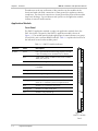
This manual describes the technical characteristics, application, installation, and
operation of the D8E1T1 used in the DXC-100 Multiservice Access Node. D8E1T1
is an 8-port E1/T1 module that supports up to eight E1 or T1 links, in any
combination, with D4 (SF), ESF or G.70x framing and AMI, B8ZS or HDB3 line
coding. The module has integral BERT and supports loopback diagnostics.
10:1 hardware redundancy is available via the DXC-100PSX unit.
Main Features
D8E1T1 simultaneously terminates both DS1 (T1) and E1 and associated framing
signals on the same card, providing a cost-effective method for performing A-law
to µ-law conversion. D4 and ESF framing modes are supported for T1 links. CRC
and CAS framing modes are supported for E1 links. N+1 redundancy is supported
for critical links.
D8E1T1 has extensive statistic gathering capability. Each of the T1/E1 framers can
report sync status, frame errors, CRC errors, frame slips, and several link alarm
conditions. Diagnostics include integral BERT and loopback diagnostics for innetwork testing. For voice applications, call processing ABCD signaling bits can be
monitored.
Software Updates
For software update procedures, refer to the Utilities chapter of the DXC-100
Installation and Operation Manual.
1.2 Physical Description
D8E1T1 Module Set, General
D8E1T1 occupies a single backplane slot in the DXC-100 chassis. The D8E1T1
module set has two circuit card modules: an application module and an interface
module. The application module (front card) contains the backplane, switching,
and framing logic. The interface module (rear card) provides electrical interface via
a 50-pin RJ-48M (50-Pin telco) connector.
Physical Description
1-1
D8E1T1 Installation and Operation Manual
Chapter 1 Overview
Thumbscrews at the top and bottom of the panels secure the modules in the
chassis and make electrical connection to frame ground for regulatory emission
compliance. The electrical connection to frame ground also protects the modules
from static discharge. Top and bottom card ejectors on the application module
facilitate its removal (and insertion).
Application Module
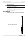
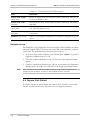
Front Panel
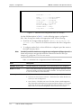
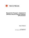
The D8E1T1 application module occupies one application module slot in the
DXC-100 chassis. The panel of the D8E1T1 application module is shown in
Figure 1-1. The module panel includes eight groups of status indicators (one group
for each link), and a common READY indicator. Table 1-1 explains the functions of
the indicators located on the module panel.
Table 1-1. D8E1T1 Module Indicators
Indicator
State
Description
STATUS
Green
Link is operational and functioning properly. The link
is free of Framing Errors, and there are no alarms.
Red
A Link Fault or alarm condition exists, such as Yellow
Alarm, AIS, LOF, etc.
OFF
The link is configured as Out of Service.
Yellow
The T1/E1 link is in a loopback condition, or link BERT
is enabled.
TEST
READY
Flashing Yellow
An error has been detected during T1/E1 link BERT.
OFF
No testing is being conducted.
Green
Module is fully operational and in an online state.
D8E1T1
1
2
3
4
5
6
Flashing Green
Module is fully operational, and in a standby state
(when N+1 redundancy has been implemented).
Red
Module is in a system bus error state.
Flashing Red
Module is in offline (fault) state
OFF
Module is not powered up.
7
8
STATUS
TEST
STATUS
TEST
STATUS
TEST
STATUS
TEST
STATUS
TEST
STATUS
TEST
STATUS
TEST
STATUS
TEST
READY
Figure 1-1.
D8E1T1 Module
Panel
1-2
Physical Description
D8E1T1 Installation and Operation Manual
Chapter 1 Overview
Other LED Indications
When all front panel LEDs are cascade lighting from top to bottom, the module is
downloading software to memory.
Caution Do not interrupt the software upgrade while it is in progress, otherwise the
D8E1T1 module configuration may be damaged. In the event of damage, please
contact RAD Technical Support Department.
If all front panel LEDs are off except the READY LED, it indicates that all links are
Out of Service.
If all LEDs are flashing, it indicates that the rear interface module is missing or the
device is being forced Out of Service.
Interface Module Panel
The interface connector of D8E1T1 is located on the interface module that plugs
into a separate compartment in the rear of the DXC-100 chassis.
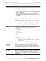
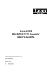
Figure 1-2 shows the panel of the D8E1T1 interface module. The interface module
has one RJ-48M connector that includes all the link interfaces.
D8E1T1
Figure 1-2. D8E1T1 Interface Module Panel
P1
Physical Description
1-3
D8E1T1 Installation and Operation Manual
Chapter 1 Overview
1.3 D8E1T1 Module Specifications
Eight
Number of Ports
Data Rate per Port
E1 – 2.048 Mbps
T1 – 1.544 Mbps
Electrical Interface
ITU-T Rec. G.703
Framing
• CRC
• CAS
• SF (D4)
• ESF
Line Code
E1 – HDB3
T1 – AMI, B8ZS
Jitter Performance
Per ITU-T Rec. G.823; ETSI TBR 13
Pulse Shape
Per ITU-T Rec. G.703
Connector
50-pin RJ-48M connector on the rear interface
module, convertible to eight RJ-45 connectors via
an adaptor cable
Timing
• Receive timing recovered from incoming line
signal or received via the DSMC.2 module
• Transmit timing locked to the DXC-100 master
(Stratum 3) clock
Redundancy
Capability
Up to 10:1 when used with in a DXC-100 nest
configured with the DXC-100PSX N+1 Protection
Switch
Indicators
• READY (green/red): indicates the status of the
module set in general
• STATUS (red/green): indicates link status
separately for each of the E1/T1 links.
• TEST (yellow) indicates test status separately for
each of the E1/T1 links.
Timeslot
Allocation
• User-defined, any timeslot to any timeslot
mapping
Diagnostics
• Local and remote loopbacks on each module
port
• BER testing on each port
• Inband code activated loopback as per ANSI
T1E1.2/93-003
1-4
D8E1T1 Module Specifications
D8E1T1 Installation and Operation Manual
Chapter 1 Overview
Power
Consumption
7.25W (1.45A at +5 VDC)
Configuration
Programmable via DXC-100 management by ASCII
terminal, Telnet or RADview Management System
Physical
Front Main Module
Height
263 mm (10.3 in)
Width
25 mm (9.8 in)
Depth
213 mm (83.8 in)
Rear Interface Module
Height
263 mm (10.3 in)
Width
25 mm (9.8 in)
Depth
127 mm (50.0 in)
D8E1T1 Module Specifications
1-5
Chapter 1 Overview
1-6
D8E1T1 Module Specifications
D8E1T1 Installation and Operation Manual
Chapter 2
Installation and Operation
2.1 Introduction
This chapter provides installation, configuration, and operation instructions for the
D8E1T1 module.
The information presented in this chapter supplements the DXC-100 installation,
configuration and operation instructions found in the DXC-100 Installation and
Operation Manual.
Warning
Before performing any internal settings, adjustment, maintenance, or repairs,
first disconnect all the cables from the module, and then remove the module
from the DXC-100 chassis.
There are no internal settings, adjustments, maintenance, or repairs for either
the operator or the user to make. These activities are performed only by a
skilled technician who is aware of the hazards involved.
Always observe standard safety precautions during installation, operation, and
maintenance of this product.
The D8E1T1 module components are sensitive to electrostatic discharge. To
prevent ESD damage, always hold the module by its sides, and do not touch the
module components or connectors. When handling this module, wear an antiESD
Caution static wrist strap connected to frame ground to prevent electrostatic discharge from
damaging the circuits.
Installing D8E1T1
2-1
Chapter 2 Installation and Operation
D8E1T1 Installation and Operation Manual
2.2 Installing D8E1T1
Note
To use N+1 redundancy, D8E1T1 must be installed in slots 2 to 10, with a
redundant module installed in slot 1 (for Narrowband Group 1).
Application Module Installation
1. Hold the application module vertically with the components on the left.
2. Slide the application module into a slot in the front of the DXC-100 chassis
following the white card guides.
3. Open both card ejectors until they are at a 90-degree angle to the module,
then slide the module further into the slot until the hook on the card ejectors is
inside the lip of the DXC-100 chassis.
4. Slowly close the card ejectors, which seats the application module in the slot.
5. Tighten the thumbscrews at the top and bottom of the application module.
Interface Module Installation
1. Hold the interface module vertically with the components on the right.
2. Slide the interface module into a slot in the rear of the DXC-100 chassis
following the white card guides.
3. Seat the interface module by slowly pressing it into place.
4. Tighten the thumbscrews at the top and bottom of the interface module.
2.3 Connecting the Cables
Link Connection Data
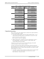
The D8E1T1 interface module has a 50-pin RJ48M connector designated P1.
Table 2-1 lists the connection pin functions.
Straight cable CBL-DXC100-D8E1T1/BAL, or cross-cable
CBL-DXC100-D8E1T1/BAL/X, terminated in 8 RJ-45 connectors, can be ordered
from RAD.
2-2
Connecting the Cables
D8E1T1 Installation and Operation Manual
Chapter 2 Installation and Operation
Table 2-1. 50-Pin Connector P1, Pin Functions
Link
1
2
3
4
Pin
Function
26
Transmit tip
1
Transmit ring
27
Receive tip
2
Link
Pin
Function
38
Transmit tip
13
Transmit ring
39
Receive tip
Receive ring
14
Receive ring
29
Transmit tip
41
Transmit tip
4
Transmit ring
16
Transmit ring
30
Receive tip
42
Receive tip
5
Receive ring
17
Receive ring
32
Transmit tip
44
Transmit tip
7
Transmit ring
19
Transmit ring
33
Receive tip
45
Receive tip
8
Receive ring
20
Receive ring
35
Transmit tip
47
Transmit tip
10
Transmit ring
22
Transmit ring
36
Receive tip
48
Receive tip
11
Receive ring
23
Receive ring
5
6
7
8
Connection Instructions
Before starting, refer to the installation plan to determine the cables intended for
connection to the D8E1T1 module.
•
Connect the standard interface cable (CBL-DXC100-D8E1T1/BAL, or crosscable CBL-DXC100-D8E1T1/BAL/X, or equivalent) to connector P1 on the
panel of the interface module and each
RJ-45 connector to the user’s equipment.
•
When the optional N+1 redundancy function is implemented, connect a
CBL-100PSX-D8E1T1 cable from connector P1 of the module to the
corresponding PSX interface module.
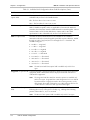
A single screw is used to attach one end of the RJ-48M plug to the module
connector standoffs on the rear interface module.
In order to securely fasten the opposite end of the plug, cable tie mounts have
been provided on the rear interface module. These mounts are located above and
below the RJ-48M connector so that tie-wraps (provided) can be used to securely
hold the plug in the connector:
•
The cable tie mount above the connector is used to attach a tie-wrap around
an interface cable (CBL-100PSX-D8E1T1) that feeds down from the
DXC-100PSX N+1 Protection Switch.
Connecting the Cables
2-3
D8E1T1 Installation and Operation Manual
Chapter 2 Installation and Operation
•
Use the cable tie mount below the connector to attach a tie-wrap around a
standard interface cable, such as CBL-DXC100-D8E1T1/BAL, that feeds from
below the DXC-100.
Refer to Figure 2-1 for a detailed view of tie-wrap attachment locations.
P1
Tie Wrap (Mounting location
shown for DXC-100 with N+1
Protection Switch)
Tie Wrap attachment
mount for DXC-100 without
N+1 Protection Switch
Figure 2-1. Tie-Wrap Attachment Locations
2.4 Normal Indications
D8E1T1 Status Indication
When a D8E1T1 module is operational, its READY indicator lights in green.
For a module in the standby state (N+1 redundancy implemented), the READY
indicator flashes in green.
Link Status Indications
The status of each D8E1T1 link is indicated by a separate set of indicators. The
normal indications for an operational link interface are as follows:
2-4
•
The STATUS indicator of an active link lights in green.
•
The TEST indicator is off. It lights in yellow when a BER test or loop is activated
on the corresponding link.
Normal Indications
Chapter 3
Configuration
3.1 Introduction
This chapter provides specific configuration information for D8E1T1 modules. The
configuration activities are performed by means of the management system used
to control the DXC-100.
Note
All the menus identify the D8E1T1 module as Octal T1/E1 or OT1E1.
This chapter covers only the configuration activities specific to D8E1T1 modules:
for general instructions and additional configuration procedures, refer to the
DXC-100 Installation and Operation Manual.
3.2 Configure a Slot for a D8E1T1 Module
Note
In order to view the menus associated with the D8E1T1 module set, a slot must be
configured for the D8E1T1 module set, and a D8E1T1 Application Module must be
resident in the corresponding front slot in the DXC-100 equipment nest.
A D8E1T1 Interface Module must also be resident in the corresponding rear slot in
the nest. If the slot does not show a “Configured Type” in the Slot Summary Menu,
refer to the text below for information on how to configure a slot.
The following procedure describes how to assign and configure a slot for the
D8E1T1 module set.
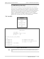
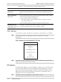
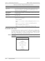
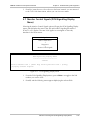
1. From the DXC-100 Main Menu, move your cursor to the System Configuration
field and press <Enter>. The following menu appears:
Configure a Slot for a D8E1T1 Module
3-1
D8E1T1 Installation and Operation Manual
Chapter 3 Configuration
Node Configuration Menu
Slot Configuration
Nest Profile
System Clock Source Menu
Users Menu
Port IP Addresses
SNMP Agent Configuration
Date and Time
TACACS Plus
Figure 3-1. Node Configuration Menu
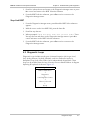
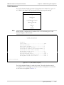
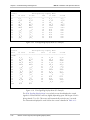
2.
Note
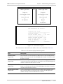
Place your cursor on the Slot Configuration field and press <Enter>. The
following menu appears, displaying slots numbered from 1 to 11.
For a DXC-100 stack, use the following sequence to reach the Slot Configuration
Menu (Figure 3-2): System Configuration → Nest Profile → Move your cursor to the
nest where the D8E1T1 module will reside → Press S.
Nest #1
Slot#
----1
2
3
4
5
6
7
8
9
10
11
Slot Configuration Menu
Device Type
---------------Octal T1/E1
Octal T1/E1
Octal T1/E1
Octal High Speed
Octal High Speed
Name
------
HDS-3
HDS-3
T3
Octal T1-E1
HDS-3
N+1 Redundancy:
N+1 Redundancy Switchover:
N+1 Redundancy Restore:
Change Card = [Enter key]
Redundancy
-----------Disable
Disable
Disable
Disable
Disable
Disable
Disable
Enable
Disable
Disable
Enable
Enable
Automatic
Manual
[D]elete Card
[P]ort/Link Cfg
Figure 3-2. Slot Configuration Menu
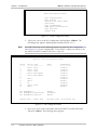
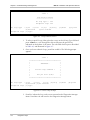
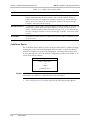
3. Move your cursor to the slot number where the D8E1T1 module will reside,
and press <Enter>. The following menu appears:
3-2
Configure a Slot for a D8E1T1 Module
D8E1T1 Installation and Operation Manual
Chapter 3 Configuration
Slot Configuration
Nest: 1
Slot: 10
Slot Name:
Card Type:
Redundancy: Disable
Figure 3-3. Slot Configuration Submenu
4. Place your cursor on the Slot Name field and press <Enter>. Type in a slot
name or number of up to 11 alphanumeric characters and press <Enter>
again.
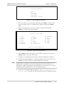
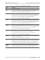
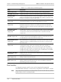
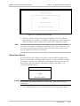
5. Select a card type. Move your cursor to the Card type field and press
<Enter>. The Card Type Menu appears:
Select a Card Type
1)
4)
7)
10)
13)
16)
19)
XCC
STM1
OC3X
DS3
QT1
DS0-DP
ROUTER
2)
5)
8)
11)
14)
17)
20)
XLC
STM1X
STS1
E3
OHSD
OCU-DP
OCTAL VOICE
3)
6)
9)
12)
15)
18)
XLCOT1E1
OC3
HDS3
OT1E1
QHSD
TAM
Enter Card Type Number: 0
Figure 3-4. Select a Card Type Menu
6. Press <Enter>, type in the number of the D8E1T1 module (12), then press
<Enter> again to store the device type.
7. Press X to save module type and return to the Slot Configuration Submenu.
8. For DXC-100 units with the N+1 Protection Switch, move your cursor to the
Redundancy field to Enable or Disable redundancy as desired.
Note
The Redundancy field will only be displayed if Narrowband Redundancy has been
Enabled and set to D8E1T1 via the Nest Profile Menu. In order to utilize N+1
redundancy, a D8E1T1 module must be installed in one of the slots 2 to 10, with a
redundant module installed in slot 1 (for Narrowband Group 1).
9. Press X to save changes. When prompted: “Update Configuration? Are
you sure (Y/N)?” Press Y. You are returned to the Slot Configuration menu.
Configure a Slot for a D8E1T1 Module
3-3
D8E1T1 Installation and Operation Manual
Chapter 3 Configuration
Change a Module Set
1. Physically remove the module set from the DXC-100 unit.
2. Move your cursor to the slot where the module set resided, and press D. A
message appears stating, “All existing connections for this slot
will be deleted.” Press Y to confirm the action or N to cancel.
Note
If you do not remove the module set prior to pressing D, the following message
appears: “-ALERT!- Can not delete a device that is present”.
3. Physically insert the new module set into the DXC-100 unit in accordance with
Chapter 2.
4. Configure the slot for the new module set. Follow the steps in the previous
procedure.
Note
A module set may also be changed without deleting the old module set by skipping
step 2 of this procedure.
3.3 D8E1T1 Module Configuration
This section will guide you through configuring the T1/E1 links for a D8E1T1
module.
Note
A module does not have to be physically present to be configured, but the slot must
be configured for that type of module.
T1/E1 Link Configuration
Navigation:
Standalone DXC-100
Main Menu
↓
System Configuration
↓
Slot Configuration
↓
Select Slot with D8E1T1 Module
↓
[P]ort/Link Cfg
3-4
D8E1T1 Module Configuration
OR
DXC-100 Stack
Main Menu
↓
System Configuration
↓
Nests Profile
↓
Select Nest with D8E1T1 Module
↓
[S]lot Conf.
↓
Select Slot with D8E1T1 Module
↓
[P]ort/Link Cfg
D8E1T1 Installation and Operation Manual
Nest #1
-01
02
03
04
05
06
07
08
Chapter 3 Configuration
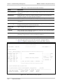
Slot #10 Links Configuration
Network Yel
Idle
Link Name
Framing
FDL LH/LBO
Loop
Alarm Code
-------------------- ----------------- ------ ------- ------- ----- ---Circuit Number
T1 ESF B8ZS
54016 0.0db
Disable Yes Busy
Circuit Number
T1 ESF AMI 62411
54016 0.0db
Disable Yes Busy
Circuit Number
T1 ESF AMI CLEAR
54016 0.0db
Disable Yes Busy
Circuit Number
T1 D4 B8ZS
0.0db
Disable Yes Busy
Circuit Number
E1
S-Haul Disable Yes Busy
Circuit Number
E1-CRC
S-Haul Disable Yes Busy
Circuit Number
E1-CAS
S-Haul Disable Yes Busy
Circuit Number
E1-CAS-CRC
S-Haul Disable Yes Busy
LH - long haul LBO - line build out[T1 only] FDL - facility data link
[C]opy cfg to all
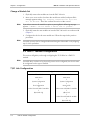
Figure 3-5. D8E1T1 Link Configuration Menu
1. To change parameters for an individual link, move the cursor to the link to be
changed and press <Enter>. The following menu appears:
Nest #1
Slot #10 Link Configuration
Link Nbr......: 1
Name..........:
Status........:
Clear T1/E1...:
LineType......:
Network Loop..:
Tx Yel Alm/RAI:
Unused DSO's..:
ESF format....:
LBO...........:
Recover Time..:
Circuit Number
In Service
Disabled
T1 ESF B8ZS
Disabled
No
Busy
54016
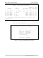
0.0db <> Long Haul
3 seconds
Figure 3-6. Individual Link Configuration Menu (T1 Example)
D8E1T1 Module Configuration
3-5
D8E1T1 Installation and Operation Manual
Chapter 3 Configuration
Nest #1
Slot #10 Link Configuration
Link Nbr......: 8
Name..........:
Status........:
Clear T1/E1...:
LineType......:
Network Loop..:
Tx Yel Alm/RAI:
Unused DSO's..:
Long Haul.....:
Circuit Number
In Service
Disabled
E1-CAS-CRC
Disabled
Yes
Busy
S-Haul
Figure 3-7. Individual Link Configuration Menu (E1 Example)
Use the field descriptions in Table 3-1 on the following pages to configure the
links. Once changes are made to the appropriate fields, do the following:
2. Press X to save changes. When prompted: “Update Configuration? Are
you sure (Y/N)?” Press Y. You are then returned to the Links Configuration
Menu.
3. To configure another link, or when all links are configured, press X to return to
the Node Summary Menu.
Note
For D8E1T1 and DT3 module sets, using the copy configuration ([C]opy cfg to all)
feature will prompt a message that will delete connections based on line type
changes (e.g., going from T1 to E1 or vice versa).
Table 3-1. Individual Link Configuration Menu Field Descriptions
Field
Description
Link Nbr: (display field)
This field displays the Link Number (1-8) of the link that you are configuring.
Name: (text field)
This is a user-defined field. Any name up to 20 alphanumeric characters can be
entered to identify each link on the D8E1T1 module. You may find it beneficial
to use circuit numbers to name the links.
Status: (option field)
This field is used to select the state of the link. You can put the link
• In Service or Out of Service In Service - The link is active. When the link is In
Service you can run diagnostics.
• Out of Service - The link is not in use. The Out of Service mode suppresses
false alarms that would otherwise be generated by the absence of a received
signal. Also, all receive and transmit path time slots in the link are set from
Busy to Idle. You cannot run diagnostics when a link is Out of Service.
3-6
D8E1T1 Module Configuration
D8E1T1 Installation and Operation Manual
Chapter 3 Configuration
Table 3-1. Individual Link Configuration Menu Field Descriptions (Cont.)
Field
Description
Clear T1/E1: (option field)
“Clear” refers to a condition where the module passes data through without
reformatting it in any way (essentially, the module acts the same as a wire). The
following selections are available:
• Framed - Framing is conveyed through the switch fabric. Allows alarms and
statistics to be displayed.
• Unframed - Full bandwidth of the frame is used for data. Passes data
without keeping track of alarms and statistics. Limited diagnostics functions
are available.
• Disabled - Framing is terminated and regenerated. Turns off Clear mode
(uses standard framing pattern and detects all alarms/errors). All diagnostic
functions are available.
Note:
LineType: (option field)
When using Clear T1 (E1) mode, make the connection ensuring that
25 (32) DS0s have connections mapped. This is necessary because of
the way Clear T1 mode operates, taking the framing bits from the first
24 (31) DS0s and sending them all out through the 25th (32nd) DS0.
See the Connection Maps Chapter in the DXC-100 Installation and
Operation Manual for details on connection mapping.
This field determines the type of framing used on the line. When Clear T1/E1 is
set to Framed or Disabled, the available line types are as follows:
• T1-ESF B8ZS
• T1-ESF AMI 62411
• T1 D4 B8ZS
• T1 D4 AMI 62411
• E1
• E1-CRC
• E1-CAS
• E1 CAS-CRC
Note:
The Long Haul and Short Haul line interface options are available with
E1 line types, and the LBO (Line Build Out) option field is available
with T1 line types.
When Clear T1/E1 is set to Unframed, the available line types will be T1 AMI,
T1 B8ZS, or E1.
Network Loop:
(option field)
This parameter determines the D8E1T1 module’s ability to respond to
diagnostic commands received from the network supplier. Enabled indicates
that the D8E1T1 Module will respond to loop commands received from the
network supplier, and Disabled indicates that it will not respond. Selectable
only in Clear T1/E1 Disabled mode.
Tx Yel Alm/RAI:
(option field)
Yes causes the T1 or E1 circuit to discard data and send a yellow alarm (T1) or
RAI (E1) if it is in a red alarm condition for the number of seconds selected in
the Recover Time field. Yes must be chosen if the network supplier is a
common carrier, such as a telephone company. Selectable only in Clear T1/E1
Disabled mode.
D8E1T1 Module Configuration
3-7
D8E1T1 Installation and Operation Manual
Chapter 3 Configuration
Table 3-1. Individual Link Configuration Menu Field Descriptions (Cont.)
Field
Description
Unused DS0’s:
(option field)
This entry is used to select the state of unused DS0s as either Busy or Idle.
Selectable only in Clear T1/E1 Disabled mode.
Idle - The hex value 7F (11111111) is sent.
Busy - The hex value FF (11111111) is sent.
ESF Format: (option field)
This entry describes the types of T1 ESF network commands to which the
D8E1T1 Module responds, and is not applicable to D4 networks. With ESF
networks, this information must be obtained from the network supplier. Choose
between 54016 (AT&T Technical Reference 54016) and T1.403 (ANSI
specification T1.403). Selectable only in Clear T1/E1 Disabled mode.
LBO: (T1 option field)
This field sets the line attenuation level, and should be set to 0 dB (no
attenuation) unless the network supplier specifically requests otherwise. 0.0 dB
through 22.5 dB = long haul; 0-133 Ft. through 655 Ft. = short haul. The
available settings are:
• 0.0 dB <> Long Haul
• 7.5 dB <> Long Haul
• 15.0 dB <> Long Haul
• 22.5 dB <> Long Haul
• 0-133 Ft. <> Short Haul
• 133-266 Ft. <> Short Haul
• 266-399 Ft. <> Short Haul
• 399-533 Ft. <> Short Haul
• 533-655 Ft. <> Short Haul
Note: The LBO (Line Build Out) option field is available only with T1 line
types.
Long Haul: (E1 option field) L-Haul (Long Haul) is the physical interface selection for long connection to E1
equipment, while S-Haul (Short Haul) is the physical interface selection for
collocated E1 equipment.
Note: The Long Haul and Short Haul line interface options are available only
with E1 line types. Long Haul/Short Haul designations for E1 are defined
by authentication of signal presented to the receiving circuitry, not by
cable length. Short Haul is defined as 0 to -6 dB, and Long Haul as 0 to
-34 dB. This loss is related to cable type and cable length.
Recover Time: (T1 option
field)
This field is used to specify how quickly Red/Yellow alarms are cleared
following the recovery of the given T1 facility (e.g., valid signal and framing
present). Select either 3, 10, or 15 seconds.
Note: The Recover Time options field is available only with T1 line types.
3-8
D8E1T1 Module Configuration
D8E1T1 Installation and Operation Manual
Chapter 3 Configuration
3.4 Accessing the D8E1T1 Main Menu
The D8E1T1 Main Menu allows you to view the configuration of the D8E1T1
module, run diagnostic tests, access utilities, view N+1 Redundancy status
(DXC-100 units with N+1 Protection Switch), and display module identification
(software and hardware revision levels). These procedures are detailed on the next
several pages.
Note
The procedure for accessing the Main Menu for a particular module set will be
different for the Standalone DXC-100 and stack versions. The Navigation Box below
shows the two different methods used to get to the Nest Summary Menu, from
which the module’s Main Menu and all subordinate menus can be accessed.
1. Use the appropriate method from the Navigation Box below to access the Nest
Summary Menu.
Navigation:
Standalone DXC-100
Main Menu
↓
Nest Summary
Note
OR
DXC-100 Stack
Main Menu
↓
Node Summary
↓
Nests Profile
↓
Nest with D8E1T1 Module
↓
Nest Summary
On the Nest Summary Menu, the Configured Type must display “Octal T1-E1” and
the Device State must display “Online” or “Standby” in order to access the D8E1T1
Main Menu. If the Device State is “Offline”, an alert message is generated.
Accessing the D8E1T1 Main Menu
3-9
D8E1T1 Installation and Operation Manual
Chapter 3 Configuration
Standby SMC not present
Alarm Contacts..: Enabled
Nest #1
N+1
Slot#
----01
02
03
04
05
06
07
08
09
10
11
SMCA
SMCB
PSX
N+1 Redundancy State: Frozen
Alarm Contact Type..: Standard
Slot Summary Menu
Group
-----
Configured Type
-----------------Test Access
---Octal High Speed
---Router
---Hybrid DS-3
---Octal T1-E1
---System Manager A
System Manager B
ProtectionSwitch
[C]lear error counts
Device State
-----------Not Present
Online
Not Present
Online
Not Present
Online
Not Present
Online
Not Present
Online
Not Present
Online
Not Present
Not Present
Alarm
----None
None
None
None
None
None
None
*Critical
None
*Major
None
None
Critical
None
[T]oggle Alarm Contacts
N+1 Device Redundancy: Switch[O]ver
[R]estore
[E]xpose
Figure 3-8. Nest Summary Menu
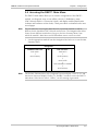
2. Then place your cursor on the slot number where the D8E1T1 module is
located and press <Enter>. The D8E1T1 Main Menu appears. See main
menu structure in Figure 3-10.
Main Menu
----------View Configuration
Diagnostics
N+1 Redundancy
Utilities
About
Figure 3-9. D8E1T1 Main Menu
3-10
Accessing the D8E1T1 Main Menu
D8E1T1 Installation and Operation Manual
Chapter 3 Configuration
OCTAL T1/E1
(D8E1T1)
MODULE MAIN
MENU
CONFIGURATION
MENU
DIAGNOSTICS
MENU
UTILITIES
MENU
N+1
REDUNDANCY
MENU
Links
Configuration
Line
Diagnostics
Center
Reset Device
Device
Redundancy
Backplane
Check
Board Status
ABOUT
DISPLAY
System Status
Monitor Control
Signals
Figure 3-10. D8E1T1 Menu Structure
3.5 View Configuration Menu
The View Configuration Menu allows you to view the configuration of the eight T1
or E1 links. To actually configure the D8E1T1 module, refer back to the previous
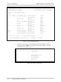
section D8E1T1 Module Configuration.
View T1/E1 Link Configuration
Navigation:
D8E1T1 Main Menu
↓
View Configuration
View Configuration Menu
3-11
D8E1T1 Installation and Operation Manual
Chapter 3 Configuration
Links Configuration
---------------------
Link Name
-- ----------------01 Circuit Number
02 Circuit Number
03
04
05
06
07
08
LH - long haul
Network
Framing
FDL
LH/LBO
Loop
--------------- ------ ------- ------T1 ESF B8ZS
54016 0.0db
Disable
T1 ESF B8ZS
54016 0.0db
Enable
Circuit Number
Out Of Service
Circuit Number
Out Of Service
Circuit Number
Out Of Service
Circuit Number
Out Of Service
Circuit Number
Out Of Service
Circuit Number
Out Of Service
LBO - line build out[T1 only]
Yel
Alarm
----No
Yes
Idle
Code
---Busy
Busy
FDL - facility data link
Figure 3-11. D8E1T1 View Links Configuration Display
From here, you can view the status of the eight T1 or E1 Links.
View Individual Link Configuration
To view a more detailed status of an individual link, move the cursor to the link to
be viewed and press <Enter>. The following display appears:
Link Configuration
-------------------Link Nbr......: 1
Name..........:
Status........:
Clear T1/E1...:
LineType......:
Network Loop..:
Tx Yel Alm/RAI:
Unused DSO's..:
ESF format....:
LBO...........:
Recover Time..:
Circuit Number
In Service
Disabled
T1 ESF B8ZS
Disabled
No
Busy
54016
0.0db <> Long Haul
3 seconds
Figure 3-12. View Individual T1/E1 Link Configuration Menu (T1 Example)
3-12
View Configuration Menu
D8E1T1 Installation and Operation Manual
Chapter 3 Configuration
Link Configuration
-------------------Link Nbr......: 8
Name..........:
Status........:
Clear T1/E1...:
LineType......:
Network Loop..:
Tx Yel Alm/RAI:
Unused DSO's..:
Long Haul.....:
Circuit Number
In Service
Disabled
E1-CAS-CRC
Disabled
Yes
Busy
S-Haul
Figure 3-13. View Individual T1/E1 Link Configuration Menu (E1 Example)
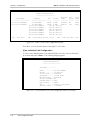
From here, you can view the configuration of one link at a time. Refer back to
Table 3-1 for an explanation of the fields in this menu.
3.6 N+1 Redundancy Menu
The N+1 Redundancy Menu allows you to view N+1 Redundancy Status. It is
applicable to DXC-100 units equipped with the DXC-100 PSX Protection Switch.
For specific information and instructions on setting up a D8E1T1 module set in a
redundancy group, refer to the DXC-100 Installation and Operation Manual.
Note
If you have only one D8E1T1 module set installed in your DXC-100, Redundancy
must be set to “Disabled”.
Navigation:
D8E1T1 Main Menu
↓
N+1 Redundancy
N+1 Redundancy Menu
--------------------Device Redundancy
Figure 3-14. D8E1T1 Module N+1 Redundancy Menu
N+1 Redundancy Menu
3-13
D8E1T1 Installation and Operation Manual
Chapter 3 Configuration
N+1 Redundancy Status Menu
Navigation:
D8E1T1 Main Menu
↓
N+1 Redundancy
↓
Device Redundancy
N+1 Redundancy Status Menu
Member of Redundancy Group: No
Card Type.................: Primary
Device State..............: Online
Frame Sync Pulse.............:
System Clock.................:
Backplane Timeslot Management:
Communication with System Mgr:
Rear Card....................:
Framers......................:
State
Change Count
--------------------OK
0
OK
0
OK
0
OK
0
OK
0
OK
0
[C]lear counters
Figure 3-15. N+1 Redundancy Status Menu
The N+1 Redundancy Status Display is a read-only screen. The only action that
can be accomplished here is pressing C to clear the counters. Descriptions for each
field on this screen are supplied in Table 3-2.
3-14
N+1 Redundancy Menu
D8E1T1 Installation and Operation Manual
Chapter 3 Configuration
Table 3-2. N+1 Redundancy Status Menu Field Descriptions
Field
Description
Member of Redundancy
Group: (display field)
Yes means that the D8E1T1 module is a member of an N+1 Redundancy
Group, while No means that it is not a member of an N+1 Redundancy
Group.
Card Type: (display field)
Displays whether the D8E1T1 module is configured as Primary or Secondary.
Device State: (display field)
Displays the current state of the D8E1T1 module as one of the following:
• Online - The card is good and is on the bus.
• Standby - The card is good and is off the bus.
• Offline - The card has general failure (failure that does not affect back-plane
operations) however, it is blocked from access to the bus.
• Defective - The card has general failure and is on the bus.
• Bus Error - The card has bus failure (failure that will impact other buses)
and is off the bus. Bus Error conditions are any or all of the following:
System clock is not present
Frame sync pulse is not present
Front or rear card is not present.
State (column)
A display of OK in this column next to any of the status entries indicates that
the function is operating properly, while a display of Missing indicates that it is
not operating properly.
Change Count (column)
Displays the number of state changes since the last time the counters were
cleared. Press C to clear the counters.
Frame Sync Pulse:
(display field)
If the state is Missing, it indicates a loss of synchronization error.
System Clock: (display field) If the state is Missing, it indicates a loss of system clock.
Backplane Timeslot
If the state is Invalid, it indicates that the backplane is flooded with more
Management: (display field) timeslots than the module can handle.
Communication with
System Mgr: (display field)
If the state is Lost, it indicates that the module has not received any messages
from the DSMC.2 for more than one minute.
Note:
If the state reads “Lost,” you most likely have problems with your Octal
T1/E1 Module, not the DSMC.2.
Rear Card: (display field)
If the state is Missing, it indicates the rear card is not being detected. The
module will reset after the rear card is detected again.
Framers: (display field)
If the state is Bad, it indicates that either one of the framers is bad (hardware
failure).
N+1 Redundancy Menu
3-15
Chapter 3 Configuration
3-16
N+1 Redundancy Menu
D8E1T1 Installation and Operation Manual
Chapter 4
Troubleshooting and
Diagnostics
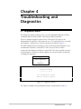
4.1 Diagnostics Menu
The Diagnostics Menu provides access to several embedded diagnostic facilities,
including loopbacks, built-in BERT, and viewing additional statistics.
There are multiple loopback options. Each of the eight T1/E1 links can be
independently looped back, and loopbacks can occur towards the line or towards
the backplane. A depiction of various loop types is provided in Figure 4-7.
The built-in BERT generator and testers can be used along with loopbacks to test
and determine the status of the D8E1T1 links. They may also be used in
conjunction with diagnostic facilities on other DXC-100 cards to qualify operation
of the backplane connections. Statistics displays are also provided for monitoring
and diagnostic purposes.
Navigation:
D8E1T1 Main Menu
↓
Diagnostics
Diagnostics Menu
---------------Line Diagnostics Center
Monitor Control Signals
Figure 4-1. Diagnostics Menu
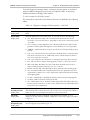
The options available from the Diagnostics Menu are described in Table 4-1.
Diagnostics Menu
4-1
D8E1T1 Installation and Operation Manual
Chapter 4 Troubleshooting and Diagnostics
Table 4-1. D8E1T1 Diagnostics Menu Option Table
Option
Description
Line Diagnostics Center
Opens the Diagnostics Center (Diagnostics Manager Menu) Menu, where the
status of the T1/E links are displayed, and from which several submenus may
accessed to perform additional diagnostic actions such as loopbacks, BERT, error
insertion, and viewing additional statistics.
Monitor Control Signals
Selecting Monitor Control Signals opens the PCM Signalling Display Menu, which
allows you to monitor the payload signaling states and transceiver control signals
on a per-link basis.
4.2 Diagnostics Center (Diagnostics Manager Menu)
The Line Diagnostics Center (Diagnostics Manager Menu) is used to set up line
diagnostics for the D8E1T1 module.
Navigation:
D8E1T1 Main Menu
↓
Diagnostics
↓
Line Diagnostics Center
Diagnostics Manager
- - - - - - - - - - - -
Link Name
-----------Circuit Num
Circuit Num
Circuit Num
Circuit Num
Circuit Num
Circuit Num
Circuit Num
Circuit Num
[B]ert
Errored
State
Seconds
-------- ------*ERROR*
3062
*ERROR*
3062
Inactive 0
Inactive 0
Inactive 0
Inactive 0
Inactive 0
Inactive 0
[L]oop
ESF [S]tatistics
[E]xpose
Link
Loop
------Off
Off
Off
Off
Off
Off
Off
Off
Bkpln
Loop
----Off
Off
Off
Off
Off
Off
Off
Off
Bert
------Off
Off
Off
Off
Off
Off
Off
Off
Test
Duration
--------0
0
0
0
0
0
0
0
Bert
Errors
-----0
0
0
0
0
0
0
0
[C]lear Error Counters
15-min Performance [R]egisters
[G].826
------------ Hit key 1 thru 9 to insert an error -----------[1]CAS Multiframe [2]Multiframe
[3]PRBS
[4]FBit
[5]Frame Alignment [6]Line Code Violation [7]Bit Slip [8]CRC [9] All
Figure 4-2. Diagnostics Manager Menu
4-2
Diagnostics Center (Diagnostics Manager Menu)
D8E1T1 Installation and Operation Manual
Chapter 4 Troubleshooting and Diagnostics
From the Diagnostics Manager Menu, a submenu may be viewed or invoked to
perform additional diagnostic actions such as loopbacks, BERT, and viewing
additional statistics including G.826 statistics.
To clear counters for all 8 links, press C.
The information contained in each field on the screen is detailed in the following
tables.
Table 4-2. Diagnostics Manager Field Descriptions – Link Fields
Field
Description
Link Name:
(display field)
Displays the user-defined name for the link, which was entered via the Configuration
Menu.
DS1/E1 State:
(display field)
This field displays the current status of the T1 or E1 link as one of the following:
• AIS - Alarm Indication Signal: AIS is set when fewer than three zero bits are
received in 512 consecutive bits or, optionally, in each of two consecutive periods
of 512 bits.
• CFA - Change of Frame Alignment: CFA is declared each time the offline framer
generates a reframe pulse that aligns the receiver timebase to a new bit position.
• *ERROR* - Undetermined error type or more than one of the above/below errors
present.
• LOF - Loss of Frame: Receive Loss Of Frame is declared when 3 consecutive FASs
have been received in error or, additionally, if bit 2 of NFAS frames has been in
error for 3 consecutive occasions.
• LOS - Loss of Signal: LOS is declared if 32 contiguous zeros have been received.
• OK - Link is In Service and functioning properly. Inactive - Link is out of service.
• RED - Red Alarm: Red Alarm or Carrier Fault Alarm declared when an out-offrame condition has been present for 2.55 sec (± 40 ms).
• RX-SLIP - Receive Slip: Controlled slip has been detected on the incoming path.
• SEF - Severely Errored Frame is reported when the receive signal does not meet
requirements of ANSI T1.231. SLIP - Slip has been detected in both the incoming
and outgoing paths.
• TX-SLIP - Transmit Slip: Controlled slip has been detected on the outgoing path.
• UnderTst - BERT is currently running on the link.
• YEL - Yellow Alarm: For T1, declares a Yellow Alarm when the Yellow pattern has
been received for 425 ms (± 50 ms). For E1, declared when an Alarm Indication is
received via TS-0 overhead (E1).
DS1/E1 ErrSecs
(Errored Seconds):
(display field)
Displays the number of errored seconds that have occurred on the T1 or E1 link since
the last time that the counter was reset. The occurrence of a Loss of Frame, CRC6, or
CRC4 error in a one-second period is known as an errored second.
Link Loop:
(display field)
This field displays the type of diagnostic loop that has been enabled, or Off is
displayed if no loop has been enabled. A depiction of various loop types is provided
in Figure 4-7.
Bkpln Loop
(Backplane Loop):
(display field)
On displayed in this field indicates that a backplane loop is enabled. A depiction of
various loop types is provided in Figure 4-7.
Diagnostics Center (Diagnostics Manager Menu)
4-3
Chapter 4 Troubleshooting and Diagnostics
D8E1T1 Installation and Operation Manual
Table 4-3. Diagnostics Manager Field Descriptions – BERT Fields
Field
Description
BERT (Testing
State): (display field)
Displays the type of BERT that is currently enabled. If BERT is not enabled, then Off
is indicated. Refer to the section titled BERT (Bit Error Rate Test) for a list of the
possible displayed states.
BERT (Test
Duration):
(display field)
Displays the amount of time (in seconds) that BERT has been enabled.
BERT (Testing)
Errors: (display field)
Displays the number of errored seconds that have occurred since BERT was enabled.
4.3 Diagnostic Test Options
The following are diagnostic tests and status displays that can be enabled on the
T1/E1 links. To run these tests, place your cursor on a numbered link and press a
hot key (see choices below):
Table 4-4. Diagnostic Test Options
Option
Description
[B]ert
Allows you to select several pseudo-random test patterns for testing the T1/E1 links.
Selectable only in Clear T1/E1 Disabled mode.
[L]oop
Allows you to enable several different loopbacks for the T1/E1 links. Selectable in all
modes.
[E]xpose
Allows you to display the status of the link and run additional procedures such as reinitializing the T1/E1 framers and injecting known errors. Selectable in all modes.
[C]lear Error
Counters
Allows you to clear all errored second and BERT counters. Selectable in all modes.
ESF [S]tatistics
Allows you to view the ESF Statistics Display, which shows current and 24-hour
statistics for the specific ESF link. Framing Statistics are only available in Clear T1/E1
Disabled mode.
15-min Performance Allows you to view the 15-Minute Performance Registers Display, which gives the same
[R]egisters
information as the ESF Statistics Display but it is broken down by link for each of the
ninety-six 15-minute intervals in the preceding 24-hour period. Framing Statistics are
only available in Clear T1/E1 Disabled mode.
[G].826:
Allows you to view the G.826 Statistics Display, which provides G.826 performance
statistics for a given T1 or E1 link for the duration of time that the link has been up
and running.
The procedures for running diagnostics and viewing statistics are detailed on the
next several pages.
4-4
Diagnostic Test Options
D8E1T1 Installation and Operation Manual
Chapter 4 Troubleshooting and Diagnostics
4.4 BERT (Bit Error Rate Test)
BERT is used to test the bit error rate of the communication circuit. The device
checks for errors by comparing a received data pattern with a known transmitted
data pattern to determine transmission line quality. If a pattern match cannot be
found, Errored Seconds counts are incremented to record the time during which a
pattern lock in the receive path could not be established. For troubleshooting
purposes, combining BERT with diagnostic loops is very useful in isolating
problems within a circuit. For the D8E1T1 module, there are 12 available BERT
patterns for the T1/E1 links (when in Clear T1/E1 Disabled mode).
T1/E1 Link BERT
Navigation:
D8E1T1 Main Menu
↓
Diagnostics
↓
Line Diagnostics Center
↓
Select a T1/E1 Link
↓
[B]ert
BERT Select
------------Link Number..:
Link Name....:
Current BERT.:
New BERT.....:
1
Circuit Number
Off
Off
Available Bit Error Tests (BERTs)
--------------------------------[o]ff
[A] Framed 2047
[C] Framed 2^15
[D] Framed 2^20
[E] Framed 2^23
[F] Framed 2^11 - 7 0's limits
[G] Framed 2^15 - 7 0's limits
[H] Framed QRSS
[I] Framed 2^23 - 14 0's limits
[0]
[1]
[2]
[3]
Framed
Framed
Framed
Framed
All Zeros (0x00)
All Ones (0xFF)
3 in 24 (0x44,0x00,0x04)
1 in 8 (0x40)
Figure 4-3. BERT Select Menu
Note
The link must be in service and Clear T1/E1 must be disabled in order to perform
BERT.
BERT (Bit Error Rate Test)
4-5
D8E1T1 Installation and Operation Manual
Chapter 4 Troubleshooting and Diagnostics
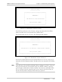
1. To select a BERT pattern, either place the cursor on the New BERT field and
press <Enter> to cycle through the choices, OR press the specific hot key
indicated on the bottom of the menu. The selectable patterns and
corresponding hot keys are shown in Table 4-5.
Table 4-5. BERT Selections
Option
Description
DS1/E1 BERT
[A]
Framed 2047
[C]
Framed 2^15 (Inverted Pattern according to ITU 0.151)
[D]
Framed 2^20
[E]
Framed 2^23 (Inverted Pattern according to ITU 0.151)
[F]
Framed 2^11 - 7 0's limits
[G]
Framed 2^15 - 7 0's limits
[H]
Framed QRSS
[I]
Framed 2^23 - 14 0's limits
[0]
Framed All Zeros (0x00)
[1]
Framed All Ones (0xFF)
[2]
Framed 3 in 24 (0x44, 0x00, 0x04)
[3]
Framed 1 in 8 (0x40)
Other Selections
[O]
Off
2. Press X to start the test. The following prompt appears:
BERT Select
------------Link Number..: 1
Li
Cu ************************************
Ne *
*
*
-MESSAGE!*
Available Bit Error T *
*
--------------------- *
*
[o]ff
*
Start New Test?
*
[A] Framed 2047
*
*
[C] Framed 2^15
*
*
[D] Framed 2^20
*
Are you sure (Y/N)?
*
[E] Framed 2^23
*
*
[F] Framed 2^11 - 7 0 ************************************
[G] Framed 2^15 - 7 0
[H] Framed QRSS
[I] Framed 2^23 - 14 0's limits
Figure 4-4. Start New Test Prompt
4-6
BERT (Bit Error Rate Test)
x00)
FF)
4,0x00,0x04)
)
D8E1T1 Installation and Operation Manual
Chapter 4 Troubleshooting and Diagnostics
3. Press Y to initiate the test and return to the Diagnostics Manager menu or press
N to cancel and return to the BERT Selection submenu.
4. From the BERT Selection submenu, press <Esc> twice to return to the
Diagnostics Manager menu.
Stop Link BERT
1. From the Diagnostics Manager menu, press B and the BERT Select submenu
appears.
2. With the cursor on the New BERT field, press the letter O.
3. Press X to stop the test.
4. When prompted: “Stop Bit Error Test? Are you sure (Y/N)?” Press
Y to stop the test and return to the Diagnostics Manager menu or press N to
cancel and return to the BERT Selection submenu.
5. From the BERT Selection submenu, press <Esc> twice to return to the
Diagnostics Manager menu.
4.5 Diagnostic Loops
Diagnostic Loops include several types of Network Interface (NI) Loops (Local,
Line, Analog, Remote, Payload, SmartJack, and User Defined) as well as a
Backplane Loop. Each of the 8 links can be independently looped back. These
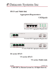
loops can be enabled from the Loop Selection screen as detailed below. A diagram
depicting all loopbacks is shown in Figure 4-7.
Navigation:
D8E1T1 Main Menu
↓
Diagnostics
↓
Line Diagnostics Center
↓
Select a T1/E1 Link
↓
[L]oop
Diagnostic Loops
4-7
D8E1T1 Installation and Operation Manual
Chapter 4 Troubleshooting and Diagnostics
Link: 1
Loop Select Screen
------------------NI Loop Type..: Off
Backplane Loop: Off
NI Loop Type
: [O]ff
[L]ocal
Li[n]e
[A]nalog
[S]martJack
[U]ser Defined
Backplane Loop: [T]oggle
[R]emote
[P]ayload
Figure 4-5. Loop Selection Screen
1. To select a specific loop, either place the cursor on the NI Loop Type field and
press <Enter> to cycle through the choices OR press the specific key
indicated on the bottom of the menu. The selectable Link loops are described
in Table 4-6, and illustrated in Figure 4-7.
2. Once you have selected a loop, press X to enable it. The following prompt
appears:
Link: 1
************************************
*
*
*
-MESSAGE!*
*
*
*
*
*
Process Loop Command ?
*
*
*
*
*
*
Are you sure (Y/N)?
*
*
*
************************************
NI Loop Type
: [O]ff
[L]ocal
Li[n]e
[S]martJack [U]ser Defined
Backplane Loop: [T]oggle
[A]nalog
[R]emote
[P]ayload
Figure 4-6. Process Loop Prompt
3. Press Y to initiate the loop, and you are returned to the Diagnostics Manager
Menu. Press N to exit and return to the Diagnostics Manager Menu.
4-8
Diagnostic Loops
D8E1T1 Installation and Operation Manual
Chapter 4 Troubleshooting and Diagnostics
Table 4-6. Loop Selection Screen Options
Option
Description
[O]ff
No loopbacks are enabled.
[L]ocal
Local Loop causes data from the DXC-100 to be looped back to itself at the Network
Interface port. (Use in Clear T1/E1 Disabled, Framed, and Unframed Mode).
See Figure 4-7 for a visual representation of this loopback.
Li[n]e
Line Loop causes frames at the NI to be looped back towards the network from the
DXC-100 unit where the command was entered. The framing is not regenerated. In a
point-to-point circuit, Line Loop is useful for looping back any testing initiated by the
other end. (Use in Clear T1/E1 Disabled, Framed, and Unframed Mode).
See Figure 4-7 for a visual representation of this loopback.
[A]nalog
Analog Line Loop causes frames at the NI to be looped back towards the network from
the DXC-100 unit where the command was entered. The framing is not regenerated. In a
point-to-point circuit, Analog Line Loop is useful for looping back any testing initiated by
the other end. (Use in Clear T1/E1 Disabled, Framed, and Unframed Mode).
See Figure 4-7 for a visual representation of this loopback.
[R]emote
Remote Loop causes a loop at the distant end of a point-to-point circuit, and is useful for
looping back testing initiated from the local side. (Use in Clear T1/E1 Disabled Mode).
Note: Payload loop will not function when using Clear T1/E1 Unframed mode.
See Figure 4-7 for a visual representation of this loopback.
[P]ayload
Payload Loop is very similar to a Line Loop, except that it only loops the data (payload)
and the framing is regenerated. (Use in Clear T1/E1 Disabled Mode.
Note: Payload loop will not function when using Clear T1/E1 Unframed mode.
See Figure 4-7 for a visual representation of this loopback.
[S]martJack
Transmits a code that is recognized by a remote SmartJack, which then puts itself into
loopback towards the DXC-100.
See Figure 4-7 for a visual representation of this loopback.
[U]ser Defined
Similar to a Smart Jack Loop, this feature allows you to place remote equipment into
loopback by sending a code to the equipment. The proper code needs to be obtained
from the remote equip- ment’s manufacturer or operator. Various elements of the code
can be defined, such as the length and value for both the activate and deactivate code.
See User-Defined Loop for further explanation of this loopback and how to set it up.
Backplane Loop
(Toggle):
(option field)
Backplane Loop is designed to check the integrity of the backplane and allow testing
through the D8E1T1 port from the remote side to the backplane and back to the tester.
Select Yes to enable the backplane loop, and No to disable the backplane loop.
Diagnostic Loops
4-9
D8E1T1 Installation and Operation Manual
Chapter 4 Troubleshooting and Diagnostics
Remote End
Local End (DXC-100)
RX
Local Loop
TX
RX
Line Loop
TX
DTE
DCE
NI
Framer
WAN
Smart Jack
NI
Framer
DCE
Module D8E1T1
Backplane
DTE
(Other Module)
(all loops initiated from this end)
TX
RX
TX
RX
For Line Loop, the framing is not regenerated and
the entire frame is looped.
RX
Payload Loop
TX
TX
RX
Payload Loop is different than a line loop, in that
it only loops the data (payload), and the framing
is regenerated.
RX
Remote Loop
TX
RX
Analog (LIU) Loop
TX
RX
SmartJack Loop
TX
Transmits a code that is recognized by a remote
SmartJack, which will then place itself into
loopback.
RX
User-Defined Loop
TX
Transmits a user-defined code that is recognized
by a remote unit, which will then place itself into
loopback.
RX
Backplane Loop
TX
Figure 4-7. D8E1T1 Diagnostic Loops
4-10
Diagnostic Loops
TX
RX
TX
RX
TX
RX
TX
RX
TX
RX
D8E1T1 Installation and Operation Manual
Chapter 4 Troubleshooting and Diagnostics
User-Defined Loop
A User-Defined Loop is similar to a Smart Jack Loop. It allows you to place remote
equipment into loopback by sending a specific code to the equipment. The proper
code needs to be obtained from the remote equipment’s manufacturer or
operator. Several elements of the code can be defined, such as the length and
value for both the activate and deactivate code.
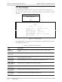
1. From the Loop Selection Menu, either place the cursor on the NI Loop Type
field and press <Enter> to cycle through the choices until User Defined is
displayed OR press U (hot key).
2. Next, press X to select the loop. The User Defined Loop parameter selection
fields appear:
Link: 1
Loop Select Screen
-----------------NI Loop Type..: User Defined
Backplane Loop: Off
Length
-----Activate Code..: 5 bits
Deactivate Code: 6 bits
Unframed.......: Yes
Value
----00001000
00100100
Notes: - Loop code uses 4,5,6 or 7 high order bits of the code value.
- Bit 7 is transmitted first.
- Unframed code overwrites the framing bits.
Figure 4-8. User Defined Loop Select Screen
3. Enter the remote loopback codes as specified by the remote equipment’s
manufacturer or operator. Refer to the field descriptions in Table 4-7 to assist
you in setting up a User- Defined Loop.
Note
You must configure the corresponding activate and deactivate codes prior to
activating the loop, otherwise the loop will not be activated.
4. Once the parameters of the loop have been defined, press X to save and
activate the loop command. When the Process Loop Command Prompt
(Figure 4-6) appears, press Y. The loop command will be sent to the remote
equipment.
Diagnostic Loops
4-11
Chapter 4 Troubleshooting and Diagnostics
D8E1T1 Installation and Operation Manual
Table 4-7. User-Defined Loop Field Descriptions
Field
Description
Activate Code - Length:
(option field)
Defines the length of the code needed to activate a remote loop. Select 4, 5, 6,
or 7 bits. The default is 5 bits.
Activate Code - Value:
(text field)
Used to enter the binary code needed to activate a remote loop. The default is
00001000.
Deactivate Code - Length:
(option field)
Defines the length of the code needed to deactivate a remote loop. Select 4, 5,
6, or 7 bits. The default is 6 bits.
Deactivate Code - Value:
(text field)
Used to enter the binary code needed to deactivate a remote loop. The default
is 00100100.
Unframed: (option field)
Select Yes if the loopback command can over-write the framing bits, or No if it
cannot.
Backplane Loop
The Backplane Loop is designed to check the integrity of the Backplane and allow
testing through the D8E1T1 port from the remote side to the backplane and back
to the tester. The backplane loop is shown as part of Figure 4-7.
1. Move your cursor to the Backplane Loop field and press <Enter> or press T to
toggle the backplane loop On or Off.
2. Press X to enable the Backplane Loop. The Process Loop Command Prompt
appears.
3. Press Y to initiate the backplane loop, and you are returned to the Diagnostics
Manager Menu. Press N to exit and return to the Diagnostics Manager Menu.
Note
There must be a connection to another module or to the D8E1T1 module itself
mapped on the backplane in order for the backplane loop to function.
4.6 Expose (Link Status)
The Expose function is used to display the status of the T1/E1 links, access G.826
statistics, reinitialize the framer, and insert errors for diagnostic purposes.
4-12
Expose (Link Status)
D8E1T1 Installation and Operation Manual
Chapter 4 Troubleshooting and Diagnostics
Expose - T1/E1 Link Status
Navigation:
D8E1T1 Main Menu
↓
Diagnostics
↓
Line Diagnostics Center
↓
Select a T1/E1 Link
↓
[E]xpose
For a T1 Link, the following display appears:
T1/E1 Link Status
----------------Link#: 1
Name: Circuit Number
-------------- State ErroredSec
Red Alarm.....: Off
0
Yellow Alarm..: Off
0
Loss Of Signal: Off
0
AIS Indication: Off
0
Out Of Frame..: Off
0
SEF Indication: Off
0
Transmit Slip.: Off
0
Receive Slip..: Off
0
Crc Errors........: 0
Bpv Errors........: 0
Frame Bit Errors...: 0
Trunk Conditioning.: On
[C]lear Counters Re[i]nitialize
ESF [S]tatistics 15-min Performance [R]egisters [G].826
------------ Hit key 1 thru 9 to insert an error
[1]CAS Multiframe [2]Multiframe
[3]PRBS
[4]FBit
[5]Frame Alignment [6]Line Code Violation [7]Bit Slip [8]CRC [9] All
Figure 4-9. T1/E1 Link Status Menu (T1 Link)
Expose (Link Status)
4-13
D8E1T1 Installation and Operation Manual
Chapter 4 Troubleshooting and Diagnostics
For an E1 Link, the following display appears:
T1/E1 Link Status
----------------Link#: 6 Name: Circuit Number
-------------- State ErroredSec
RAI...........: Off
0
MFRAI.........: Off
0
Loss Of Signal: Off
0
AIS Indication: Off
0
Out Of Frame..: Off
0
SEF Indication: Off
0
Transmit Slip.: Off
0
Receive Slip..: Off
0
[C]lear Counters
Crc Errors.........:
Bpv Errors.........:
Frame Bit Errors...:
Trunk Conditioning.:
Far End Block Errs.:
0
0
0
On
0
Re[i]nitialize
ESF [S]tatistics
15-min Performance [R]egisters
[G].826
------------ Hit key 1 thru 9 to insert an error ----------------[1]CAS Multiframe [2]Multiframe
[3]PRBS
[4]FBit
[5]Frame Alignment [6]Line Code Violation [7]Bit Slip [8]CRC [9] All
Figure 4-10. T1/E1 Link Status Menu (E1 Link)
The information contained in each field on the screen is detailed in Table 4-8 on
the following page. Some of the fields are context sensitive, (e.g., the CRC errors
only appear for links that support CRC such as T1 ESF or E1 CRC). An error-free
link will display zeroes in all counter fields.
From the T1/E1 Link Status submenu, you can do the following:
•
Press C to clear counters for the selected link (refer to page 4-16).
•
Press S to view ESF Statistics (refer to page 4-16).
•
Press i to reinitialize the T1/E1 framer (refer to page 4-18).
•
Press R to view 15-Minute Performance Registers (refer to page 4-19).
•
Press G to view G.826 Statistics (refer to page 4-21).
You can also use keys 1 through 9 to insert errors from the NI side, which is then
shown on the remote side. If the remote side is line looped, the inserted errors will
be seen on the local side, under Errored Seconds.
Table 4-8. T1/E1 Link Status Menu Field Descriptions
Field
Description
Link#: (display field)
Displays the link number of the exposed link.
Name: (display field)
Displays the user-defined name for the link, which was entered via the
Configuration Menu.
Error: (column)
Displays the type of error for the specific T1/E1 link.
4-14
Expose (Link Status)
D8E1T1 Installation and Operation Manual
Chapter 4 Troubleshooting and Diagnostics
Table 4-8. T1/E1 Link Status Menu Field Descriptions (Cont.)
Field
Description
State: (column)
A display of On in this column next to any of the Error entries indicates that an
error condition currently exists on the T1 or E1 link. A display of Off indicates
that the error condition is not present, but if the errored seconds field has a
count, then this alarm has occurred sometime in the past (since the last time
that the counter was cleared).
Note:
All Error and Alarm states will only be detected in Clear T1/E1 Disabled
mode, except for LOS and BPV. These will also be detected in Clear
T1/E1 Framed mode.
ErrSecs (Errored Seconds): The display count in this column indicates the quantity of seconds that the error
(column)
condition on the T1 or E1 link has been present or was present. Press C to clear
the counters for this link.
Red Alarm:
(T1 display field)
A display of On indicates that a loss of frame alignment has occurred and
synchronization has been lost.
Yellow Alarm:
(T1 display field)
A Yellow Alarm is generated by the network and sent to the customer premises.
It usually means that the network is not correctly receiving the DXC-100 signal
(the network is not in sync or a Red Alarm has occurred).
RAI: (E1 display field)
A display of On indicates that a Remote Alarm Indication has been received
(via TS-0 overhead).
MFRAI: (E1 display field)
A display of On indicates that a Far end Channel Associated Signalling (CAS)
Multi-Frame (MF) alarm indication received (via TS-16 overhead).
Loss of Signal:
(display field)
This field will display On to indicate a loss of signal detection. No T1 or E1
signal is present on the RX pair to the DXC-100.
AIS Indication:
(display field)
A display of On indicates that an unframed “all ones” condition has been
detected. After AIS (Alarm Indication Signal) is detected, the system will return
a yellow alarm signal and pass on channel trunk conditioning.
Out of Frame:
(display field)
A display of On indicates that the received link data stream does not meet preset framing criteria.
SEF Indication:
(display field)
A display of On indicates that a Severely Errored Frame has been detected (the
receive signal does not meet the requirements of ANSI T1.231).
Transmit Slip:
(display field)
A display of On indicates that slip has been detected in the outgoing path.
Receive Slip: (display field)
A display of On indicates that slip has been detected in the incoming path.
CRC Errors (Cyclic
Redundancy Check
Errors): (display field)
The CRC test is a 6-bit algorithm that checks the content of the entire frame.
For T1 (ESF framing), this field indicates the number of CRC6 block errors that
have been detected. D4 framing does not include CRC6; DXC-100 replaces
that parameter by counting the number of framing bit errors. The result is a
useful picture over time regarding D4 link performance. For E1, this field
indicates the number of CRC4 block errors that have been detected.
Bpv Errors (Bi-Polar
Violation Errors):
(display field)
This field is a counter that records the number of Bipolar Violations that have
been detected. This usually indicates that a very weak or excessively strong
signal is being received from the network.
Expose (Link Status)
4-15
D8E1T1 Installation and Operation Manual
Chapter 4 Troubleshooting and Diagnostics
Table 4-8. T1/E1 Link Status Menu Field Descriptions (Cont.)
Field
Description
Frame Bit Errors:
(display field)
This field is a counter that records the number of frame alignment bit errors
that have been detected. This does not mean that synchronization has been
lost.
Trunk Conditioning:
(display field)
If trunk conditioning status is On and the control bits indicate a Red or Yellow
alarm is being received, the following occurs:
• Receive data is disabled at all timeslots.
• Idle code is written to corresponding slip buffer according to content of
each timeslot (data/voice).
If trunk conditioning status is Off, then no alarms are being received.
Far End Block Errors:
(display field) (E1 CRC and
E1-CAS-CRC Only)
This field is a counter that records the number of Far End Block Errors that have
been detected (Remote CRC errors are reported as FEBEs).
Clear Counters
You may elect to either clear the error counters for a specific link, or for all links.
Note
There are no prompts for clearing the counters. All counters are cleared
immediately.
Clear Counters for an Individual T1/E1 Link
Navigation:
D8E1T1 Main Menu
↓
Diagnostics
↓
Line Diagnostics Center
↓
Select a T1/E1 Link
↓
[E]xpose
↓
[C]lear Counters
Note
If you do not first press E (Expose) for the individual link before pressing C (Clear
Counters), ALL link counters will be cleared.
ESF Statistics
The ESF Statistics Display is a read-only display. It allows you to view both current
and 24-hour ESF Statistics. The Current Statistics column displays the counts for
the current time interval (maximum 15 minutes). The 24 Hour Statistics column
displays the counts for the preceding 24-hour period. The information has no
meaning in Clear T1/E1 Unframed mode.
Note
4-16
ESF Statistics cannot be displayed for a D4-framed or E1 link.
Expose (Link Status)
D8E1T1 Installation and Operation Manual
Chapter 4 Troubleshooting and Diagnostics
Navigation:
D8E1T1 Main Menu
↓
Diagnostics
↓
Line Diagnostics Center
↓
Select T1/E1 Link
↓
ESF [S]tatistics
OR
D8E1T1 Main Menu
↓
Diagnostics
↓
Line Diagnostics Center
↓
Select T1/E1 Link
↓
[E]xpose
↓
ESF [S]tatistics
ESF Statistics For Port#: 1
Register Curr 24 Hr
---------------------------------Errored seconds.........: 0 1
Failed seconds (UAS)....: 727 5391
Severely errored seconds: 0 1
Bursty errored seconds..: 0 0
Loss of frame count.....: 0 0
Time in interval........: 727
# Valid intervals.......: 6
ESF status..............: FU000000
Figure 4-11. ESF Statistics Display
The information contained in each field on the screen is detailed in Table 4-9.
Table 4-9. ESF Statistics Display Field Descriptions
Field
Description
Errored Seconds:
(display field)
The occurrence of a Loss of Frame or a CRC6 error in a one-second period is
known as an errored second. This field displays the number of errored seconds
that have occurred.
Failed Seconds (UAS):
(display field)
Each one-second period during the occurrence of a Failed Signal State (10
consecutive errored seconds) is known as a failed second. This field displays the
number of failed seconds that have occurred.
Severely Errored Seconds:
(display field)
A one-second period in which 320 or more CRC6 errors have occurred is
known as a severely errored second. This field displays the number of severely
errored seconds that have occurred.
Bursty Errored Seconds:
(display field)
A one-second period in which more than one but less that 320 CRC6 errors
have occurred is known as a bursty errored second. This field displays the
number of bursty errored seconds that have occurred.
Expose (Link Status)
4-17
D8E1T1 Installation and Operation Manual
Chapter 4 Troubleshooting and Diagnostics
Table 4-9. ESF Statistics Display Field Descriptions (Cont.)
Field
Description
Loss of Frame Count:
(display field)
A loss of frame occurs when either Network equipment or the DTE senses
errors in the framing pattern. Depending upon the equipment, this occurs
when any 2 of 4, 2 of 5, or 3 of 5 consecutive terminal framing bits received
contain bit errors in the framing pattern.
Time in Interval:
(display field)
A timer that tracks the number of seconds (0-900) since the start of the current
15-minute interval.
# Valid Intervals:
(display field)
A counter that tracks the total number of 15-minute intervals in a 24 hour
period (up to 96).
ESF Status: (display field)
This field defines the status of the T1/E1 line. The status is defined by an 8-digit
number that is described below:
Example: F00000L0
Digit #1 - “F” or “0” where “F” indicates Failed Signal State (FSS) if “U” or “L”
is true.
Digit #2 - “U” or “0” where “U” indicates an unavailable signal state.
Digit #3 through #6 and #8 are always “0.”
Digit #7 - “L” or “0” where “L” indicates that the T1 line is in loop.
Re-initialize T1/E1 Framer
The Re-initialize function is used to reset the T1/E1 link framer to its default values.
It is used to rewrite values for the framer if you suspect that a configuration change
didn’t take or odd problems are occurring on the status displays. This function will
only reset the T1/E1 link framer, not the entire module.
Caution Re-initializing the framer will cause data to be momentarily interrupted for the
selected link.
Navigation:
D8E1T1 Main Menu
↓
Diagnostics
↓
Line Diagnostics Center
↓
Select a T1/E1 Link
↓
[E]xpose
↓
Re[i]nitialize
4-18
Expose (Link Status)
D8E1T1 Installation and Operation Manual
Chapter 4 Troubleshooting and Diagnostics
T1/E1 Link Status
----------------Link#: 1 Name: Circuit Number
-------------- Stat
Red Alarm.....: On ***************************************
Yellow Alarm..: Off *
*
Loss Of Signal: On *
-MESSAGE!*
AIS Indication: Off *
*
Out Of Frame..: On *
*
SEF Indication: On * Reset and re-configure the framer? *
Transmit Slip.: Off *
*
Receive Slip..: Off *
*
*
Are you sure (Y/N)?
*
*
*
***************************************
[C]lear Counters
Re[i]nitialize
ESF [S]tatistics
15-min Performance
[R]egisters
[G].826
------------ Hit key 1 thru 9 to insert an error-----------------------[1]CAS Multiframe
[2]Multiframe
[3]PRBS
[4]FBit
[5]Frame Alignment [6]Line Code Violation
[7]Bit Slip
[8]CRC
[9] All
Figure 4-12. Reset Framer Prompt
1. Press Y. The T1/E1 framer will be re-initialized, and you are returned to the
T1/E1 Link Status submenu. Press N, and you are returned directly to the
T1/E1 Link Status Menu without the framers being re-initialized.
15-Minute Performance Registers
The 15-Minute Performance Registers Display is a read-only display. It provides
the same information as the ESF Statistics Display, but it is broken down by link for
each of the ninety-six 15-minute intervals in the preceding 24-hour period. The
information has no meaning in Clear T1/E1 Unframed mode.
Navigation:
D8E1T1 Main Menu
↓
Diagnostics
↓
Line Diagnostics Center
↓
Select T1/E1 Link
↓
15-min Performance [R]egisters
Note
OR
D8E1T1 Main Menu
↓
Diagnostics
↓
Line Diagnostics Center
↓
Select T1/E1 Link
↓
[E]xpose
↓
15-min Performance [R]egisters
15-Minute Performance Registers cannot be displayed for a D4-framed link.
Expose (Link Status)
4-19
D8E1T1 Installation and Operation Manual
Chapter 4 Troubleshooting and Diagnostics
15-min Performance Registers For Port#: 2
INT ES FS SES BES
INT ES FS SES BES
INT ES FS SES BES
----------------------------------------------------------------01. 000 900 000 000
17. 000 000 000 000
33. 000 000 000 000
02. 000 900 000 000
18. 000 000 000 000
34. 000 000 000 000
03. 000 900 000 000
19. 000 000 000 000
35. 000 000 000 000
04. 000 900 000 000
20. 000 000 000 000
36. 000 000 000 000
05. 001 891 001 000
21. 000 000 000 000
37. 000 000 000 000
06. 000 000 000 000
22. 000 000 000 000
38. 000 000 000 000
07. 000 000 000 000
23. 000 000 000 000
39. 000 000 000 000
08. 000 000 000 000
24. 000 000 000 000
40. 000 000 000 000
09. 000 000 000 000
25. 000 000 000 000
41. 000 000 000 000
10. 000 000 000 000
26. 000 000 000 000
42. 000 000 000 000
11. 000 000 000 000
27. 000 000 000 000
43. 000 000 000 000
12. 000 000 000 000
28. 000 000 000 000
44. 000 000 000 000
13. 000 000 000 000
29. 000 000 000 000
45. 000 000 000 000
14. 000 000 000 000
30. 000 000 000 000
46. 000 000 000 000
15. 000 000 000 000
31. 000 000 000 000
47. 000 000 000 000
16. 000 000 000 000
32. 000 000 000 000
48. 000 000 000 000
[N]ext Page
Figure 4-13. 15-Minute Performance Registers Display
Press N to view the next 48 intervals. The information contained in each field on
the screen is detailed in Table 4-10.
Table 4-10. 15-Minute Performance Registers Display Field Descriptions
Field
Description
INT (Interval):
(display field)
The interval number for the ninety-six 15-minute intervals preceding the
current interval, with 01 being the most recent.
ES (Errored Seconds):
(display field)
The occurrence of a Loss of Frame or a CRC6 error in a one-second period is
known as an errored second. This field displays the number of errored seconds
that have occurred.
FS (Failed Seconds):
(display field)
Each one-second period during the occurrence of a Failed Signal State (ten
consecutive errored seconds) is known as a failed second. This field displays the
number of severely errored seconds that have occurred.
SES (Severely Errored
Seconds): (display field)
A one-second period in which three hundred twenty (320) or more CRC6
errors have occurred is known as a severely errored second. This field displays
the number of severely errored seconds that have occurred.
BES (Bursty Errored
A one-second period in which more than one but less than 320 CRC6 errors
has occurred is known as a bursty errored second. This field displays the
Seconds): (display field)
(displayed for T1 links only) number of bursty errored seconds that have occurred.
4-20
Expose (Link Status)
D8E1T1 Installation and Operation Manual
Chapter 4 Troubleshooting and Diagnostics
G.826 Statistics
The G.826 Statistics Display provides G.826 performance statistics for a given T1
or E1 link for the duration of time that the link has been up and running.
Navigation:
D8E1T1 Main Menu
↓
Diagnostics
↓
Line Diagnostics Center
↓
Select a T1/E1 Link
↓
[E]xpose
↓
[G].826
Note
When the link is configured for E1 (without CRC) or T1 D4 framing, the G.826
Statistics Display is not accessible.
G.826 Statistics
---------------Link#: 1
Total Time..........................:
Errored Seconds.....................:
Error Free Seconds..................:
Severely Errored Seconds............:
Consecutive Severely Errored Seconds:
Consecutive Error Free Seconds......:
Background Block Error..............:
Unavailable Seconds.................:
Errored Seconds Ratio...............:
Severely Errored Seconds Ratio......:
Background Block Error Ratio........:
5316
0
0
0
0
0
0
5316
0.00 %
0.00 %
0.00 %
[C]lear Counters
Figure 4-14. G.826 Statistics Display
The G.826 Statistics Display is a read-only screen. The only action that can be
accomplished here is pressing C to clear the counters. Descriptions for each field
on this screen are supplied in Table 4-11.
Expose (Link Status)
4-21
Chapter 4 Troubleshooting and Diagnostics
D8E1T1 Installation and Operation Manual
Table 4-11. G.826 Statistics Field Descriptions
Field
Description
Link #: (display field)
Displays the number of the link for which the status is being presented.
Total Time: (display field)
Displays the amount of time (in seconds) that the link has been up and running.
Errored Seconds:
(display field)
A one-second period with one or more errored blocks or at least one defect is
known as an errored second. This field displays the number of errored seconds
that have occurred since the last counter reset.
Error Free Seconds:
(display field)
A one-second period of time during which the link was error-free. This field
represents the number of error-free seconds that have occurred.
Severely Errored Seconds:
(display field)
A subset of errored seconds, a one-second period in which more than 30% of
the blocks contain errors is known as a severely errored second. This field
displays the number of severely errored seconds that have occurred since the
last counter reset.
Consecutive Severely
Errored Seconds:
(display field)
A continuous occurrence of severely errored seconds, in one-second intervals,
which contain >30% or more errored blocks. This field represents the number
of consecutive severely errored seconds that have occurred since the last
counter reset.
Consecutive Error Free
Seconds: (display field)
A display of consecutive one-second period intervals that did not have defects
or errors on the link. This field displays the number of consecutive error-free
seconds that have occurred since the last counter reset.
Background Block Error:
(display field)
An errored block not occurring as part of a severely errored second. This field
displays the number of background block errors that have occurred since the
last counter reset.
Unavailable Seconds:
(display field)
The number of unavailable seconds that have occurred on the link during the
current interval. At the onset of 10 consecutive SES events, a period of
unavailable seconds begins. These 10 seconds are part of the unavailable
seconds count. At the end of 10 consecutive non-SES events, a new period of
available time begins. These 10 seconds are part of available time. Unavailable
seconds are not counted when factoring ratios.
Errored Seconds Ratio:
(display field)
Displays the ratio of errored seconds to total seconds in available time during a
fixed measurement interval.
Severely Errored Seconds
Ratio: (display field)
Displays the ratio of severely errored seconds to total seconds in available time
during a fixed measurement interval.
Background Block Error
Ratio: (display field)
Displays the ratio of background block errors to total blocks in available time
during a fixed measurement interval. The count of total blocks excludes all
blocks during severely errored seconds.
Error Insertion
For diagnostic purposes, specific errors can be inserted and momentarily
transmitted either directly to a remote unit or looped back to the D8E1T1 module.
Note
4-22
Errors cannot be inserted into an unframed link; the error-insertion hot keys will be
disabled when a link is in unframed mode.
Expose (Link Status)
D8E1T1 Installation and Operation Manual
Chapter 4 Troubleshooting and Diagnostics
Navigation:
D8E1T1 Main Menu
↓
Diagnostics
↓
Line Diagnostics Center
↓
Select T1/E1 Link
↓
Specific Error Hot Key
OR
D8E1T1 Main Menu
↓
Diagnostics
↓
Line Diagnostics Center
↓
Select T1/E1 Link
↓
[E]xpose
↓
Specific Error Hot Key
T1/E1 Link Status
----------------Link#: 1
Name: Circuit Number
-------------- State ErroredSec
Red Alarm.....: On
0
Yellow Alarm..: Off
0
Loss Of Signal: On
0
AIS Indication: Off
0
Out Of Frame..: On
0
SEF Indication: On
0
Transmit Slip.: Off
0
Receive Slip..: Off
0
[C]lear Counters
Crc Errors.........:
Bpv Errors.........:
Frame Bit Errors...:
Trunk Conditioning.:
0
0
0
On
Re[i]nitialize
ESF [S]tatistics
15-min Performance [R]egisters [G].826
------------ Hit key 1 thru 9 to insert an error-----------------------[1]CAS Multiframe
[2]Multiframe
[3]PRBS
[4]FBit
[5]Frame Alignment [6]Line Code Violation [7]Bit Slip [8]CRC [9] All
Figure 4-15. T1/E1 Link Status Menu - Error Insertion Choices
1. Press the specific numeric key indicated on the bottom of the menu to insert a
momentary error. The errors and their corresponding hot keys are detailed in
Table 4-12.
Expose (Link Status)
4-23
D8E1T1 Installation and Operation Manual
Chapter 4 Troubleshooting and Diagnostics
Table 4-12. T1/E1 Link Error Insertion Selections
Option
Description
[1] CAS Multiframe
Injects a single MAS pattern error by performing a logical inversion of the first MAS bit
transmitted.
[2] Multiframe
MultiFrame Error - Causes Fs (T1 D4/SF and ESF) or MFAS (E1 CAS and NSA) by
logically inverting the next frame bit/word transmitted.
[3] PRBS
Injects a single PRBS error by logically inverting the next PRBS generator output bit.
[4] FBit
Injects a single frame bit error by performing a logical inversion of the next frame bit
transmitted.
[5] Frame Alignment Forces a one-bit shift in the location of transmit frame alignment by deleting (or
inserting) one bit position from the transmit frame.
[6] Line Code
Violation
Injects a single Line Code Violation error.
[7] Bit Slip
Injects a bit slip error by deleting or repeating one data frame. The framer determines
in which direction the bit slip will occur.
[8] CRC
Injects a single CRC-6 (T1 ESF) or CRC-4 (E1 CAS/CRC and NSA/CRC) bit error by
performing a logical inversion of the next CRC bit transmitted.
[9] All
Injects all of the above errors concurrently (as applicable).
2. Once the appropriate hot key has been pressed, a prompt similar to
Figure 4-16 appears. It displays the type of error that will be inserted.
T1/E1 Link Status
Link Name.: Link 02
-----------------
Link Number: 2
DS1/E1 Status
Error State ErrSecs
--------------------Red Alm: Off 55
Yel Alm: Off 0
AIS Ind: Off 0
OOF....: Off 64
SEF Ind: Off 65
Tx Slip: Off 6
Rx Slip: Off 65
************************************
*
*
*
-MESSAGE!*
*
*
*
*
*
Insert Bit Slip error?
*
*
*
*
*
* Are you sure (Y/N)? * ErrSecs..: 0
*
*
************************************
.........:
.........:
rors.....:
itioning.:
1025
0
4100
Off
t ErrSecs: 0
[C]lear Counters Re[i]nitialize
ESF [S]tatistics 15-min Performance [R]egisters
[G].826
----------------- Hit key 1 thru 8 to insert an error ----------------[1]CAS Multiframe
[2]Multiframe [3]PRBS
[4]FBit
[5]Frame Alignment
[6]Bit Slip
[7]CRC
[8]All
Figure 4-16. Error Insertion Prompt (Typical)
4-24
Expose (Link Status)
D8E1T1 Installation and Operation Manual
Chapter 4 Troubleshooting and Diagnostics
3. Press Y to insert the error. Once the error has been inserted, you are returned
to the T1/E1 Link Status Menu, where you can view error status.
4.7 Monitor Control Signals (PCM Signalling Display
Menu)
Selecting the Monitor Control Signals option will open the PCM Signalling Display
menu, which displays the state of the AB, and/or ABCD signaling bits within a
PCM (T1 or E1) stream. The state "N/A" applies to unassigned or data-only
timeslots in the PCM stream.
Navigation:
D8E1T1 Main Menu
↓
Diagnostics
↓
Monitor Control Signals
PCM Signalling Display Menu
--------------------------Link:01
Select another link = [Enter key] Select previous link = [B key]
[D]isplay Control Signals
Figure 4-17. PCM Signalling Display Menu
1. From the PCM Signalling Display Menu, press <Enter> to toggle to the link
number you want to view.
2. Press D, and the following menu appears displaying the selected link:
Monitor Control Signals (PCM Signalling Display Menu)
4-25
Chapter 4 Troubleshooting and Diagnostics
D8E1T1 Installation and Operation Manual
Link:1
PCM Signalling Display Menu
DSO
To Link
To Bus
DSO
To Link
To Bus
-------------------------------------------------------------01
A_C_
A_C_
13
A_C_
A_C_
02
A_CD
A_CD
14
A_CD
A_CD
03
AB__
AB__
15
AB__
AB__
04
AB_D
AB_D
16
AB_D
AB_D
05
ABC_
ABC_
17
Data
Data
06
ABCD
ABCD
18
Data
Data
07
___D
___D
19
N/A
N/A
08
__C_
__C_
20
N/A
N/A
09
_CD_
_CD_
21
N/A
N/A
10
_B__
_B__
22
N/A
N/A
11
_B_D
_B_D
23
N/A
N/A
12
_BC_
_BC_
24
N/A
N/A
Figure 4-18. PCM Signalling Display Menu (T1 Example)
Link:8
PCM Signalling Display Menu
Chls
To Link
To Bus
Chls
To Link
To Bus
-------------------------------------------------------------FRAME
01
A_C_
A_C_
16
A_CD
A_CD
02
A_CD
A_CD
17
AB_D
AB_D
03
AB__
AB__
18
ABCD
ABCD
04
AB_D
AB_D
19
A_CD
A_CD
05
ABCD
ABCD
20
AB_D
AB_D
06
___D
___D
21
_B_D
_B_D
07
__C_
__C_
22
___D
___D
08
_CD_
_CD_
23
ABCD
ABCD
09
_B_D
_B_D
24
A_C_
A_C_
10
_BC_
_BC_
25
AB_D
AB_D
11
_CD_
_CD_
26
___D
___D
12
___D
___D
27
N/A
N/A
13
_CD_
_CD_
28
N/A
N/A
14
A_CD
A_CD
29
ABCD
ABCD
15
___D
___D
30
_B_D
_B_D
CAS
N/A
N/A
Figure 4-19. PCM Signalling Display Menu (E1 Example)
The PCM Signaling Display Menu is a read-only screen that displays the control
signals for a selected link. It will vary slightly depending upon which type of link is
being viewed (T1 or E1). This screen will automatically refresh every 5 seconds.
The information displayed in each field on the screen is detailed in Table 4-13.
4-26
Monitor Control Signals (PCM Signalling Display Menu)
D8E1T1 Installation and Operation Manual
Chapter 4 Troubleshooting and Diagnostics
Table 4-13. PCM Signalling Display Menu Field Descriptions
Field
Description
Link: (display field)
Displays the link number for which the control signals are shown.
DS0: (T1 display field)
Displays the time slot (DS0) for which the control signals are being reported.
Chls: (E1 display field)
Displays the channel for which the control signals are being reported.
To Link: (display field)
Displays the status of signalling towards the link. N/A indicates that the timeslot has
not been mapped, or that it is a signaling or framing channel such as E1 CAS. Data
indicates that the timeslot is being used to pass data. Voice traffic is indicated by
the display of signalling bits in an ABCD format, depending upon application. A
letter (A, B, C, or D) indicates a logic “high” or one, while an underscore indicates
a logic “low” or zero.
To Bus: (display field)
Displays the PCM signaling bit status (per ATT Technical Reference 43801) in the
direction of the DXC-100 backplane. N/A indicates that the timeslot has not been
mapped. Data indicates that the timeslot is being used to pass data. Voice traffic is
indicated by the display of signaling bits in an ABCD format, depending upon
application. A letter (A, B, C, or D) indicates a logic “high” or one, while an
underscore indicates a logic “low” or zero.
4.8 Utilities Menu
The Utilities Menu provides access to three submenus from which you can
perform a Cold Reset, a Warm Reset, or change the module’s status to In Service or
Out of Service.
Navigation:
D8E1T1 Main Menu
↓
Utilities
Utilities Menu
---------------Cold Reset Device
Warm Reset Device
Board Status: In Service
Figure 4-20. Utilities Menu
Caution A Cold Reset takes approximately 30 seconds and a Warm Reset takes
approximately 15 seconds. Both will cause data to be briefly interrupted; use a
Warm Reset for minimum interruption.
Utilities Menu
4-27
D8E1T1 Installation and Operation Manual
Chapter 4 Troubleshooting and Diagnostics
Table 4-14. Utilities Menu Option Table
Option
Description
Cold Reset Device
The Cold Reset Device utility resets the entire D8E1T1 module including resetting the
framers and downloading the Xilinx software, and causes the D8E1T1 module to
initialize to its power-up configuration. During this boot-up cycle, no user data will
flow for about 30 seconds. Since the configuration resides on the System Manager
Controller, connections will be restored.
Warm Reset Device
The Warm Reset Device utility causes the D8E1T1 module to initialize to its power- up
configuration. A Warm Reset takes approximately 15 seconds, and does not reset
framers or download Xilinx software. During this boot-up cycle, no user data will flow.
Since the configuration resides on the System Manager Controller, connections will be
restored.
Board Status
The Board Status utility allows the administrator to put the D8E1T1 module In Service
or Out of Service.
Cold Reset Device
The Cold Reset Device utility is used to reset the entire D8E1T1 module including
resetting the framers and downloading the Xilinx software. It causes the D8E1T1
module to initialize to its power-up configuration, and during this boot-up cycle,
no user data will flow. Since the module configuration resides on the DSMC.2, all
connections will be restored.
Navigation:
D8E1T1 Main Menu
↓
Utilities
↓
Cold Reset Device
Caution A Cold Reset takes approximately 30 seconds, and causes data to be briefly
interrupted; if possible use a Warm Reset for less interruption.
1. Once Cold Reset Device has been selected, the following prompt appears:
4-28
Utilities Menu
D8E1T1 Installation and Operation Manual
Chapter 4 Troubleshooting and Diagnostics
Utilities Menu
---------------************************************
*
*
*
-MESSAGE!*
*
*
*
*
*
Reset Device?
*
*
*
*
*
*
Are you sure (Y/N)?
*
*
*
************************************
Figure 4-21. Cold Reset Device Prompt
2. Press Y to reset the board, and wait for the module to reset. This will take
approximately 30 seconds for a Cold Reset, after which you will be returned to
the Nest Summary Menu and the Device State will be displayed as Online.
Note
Once you have been returned to the Nest Summary Menu, the D8E1T1 module’s
state will cycle through a combination of Standby, Out of Service, and Online. This
is a normal occurrence when the device resets. Wait for the Device State on the
menu to display Online before you proceed.
Warm Reset Device
The Warm Reset Device utility is also used to reset the D8E1T1 module, but it
does not reset framers or download Xilinx software. It causes the D8E1T1 module
to initialize to its power-up configuration, and during this boot-up cycle, no user
data will flow. Since the module configuration resides on the DSMC.2, all
connections will be restored.
Navigation:
D8E1T1 Main Menu
↓
Utilities
↓
Warm Reset Device
Caution A Warm Reset takes approximately 15 seconds, and causes data to be briefly
interrupted.
1. Once Warm Reset Device has been selected, the following prompt appears:
Utilities Menu
4-29
D8E1T1 Installation and Operation Manual
Chapter 4 Troubleshooting and Diagnostics
Utilities Menu
---------------************************************
*
*
*
-MESSAGE!*
*
*
*
*
*
Warm Reset Device?
*
*
*
*
*
*
Are you sure (Y/N)?
*
*
*
************************************
Figure 4-22. Warm Reset Device Prompt
2. Press Y to reset the board, and wait for the module to reset. This will take
approximately 15 seconds for a Warm Reset, after which you will be returned
to the Nest Summary Menu and the Device State will be displayed as Online.
Note
Once you have been returned to the Nest Summary Menu, the D8E1T1 module’s
state will cycle through a combination of Standby, Out of Service, and Online. This
is a normal occurrence when the device resets. Wait for the Device State on the
menu to display Online before you proceed.
Board Status
The Board Status option allows the Administrator to put a device In Service or Out
of Service.
Note
If a module is set to Out of Service, you cannot enter the Diagnostics Menu.
Navigation:
D8E1T1 Main Menu
↓
Utilities
↓
Board Status
If the board status was In Service, the following prompt appears:
4-30
Utilities Menu
D8E1T1 Installation and Operation Manual
Chapter 4 Troubleshooting and Diagnostics
Utilities Menu
---------------************************************
*
*
*
-MESSAGE!*
*
*
*
*
*
Set device to Out Of Service? *
*
*
*
*
*
Are you sure (Y/N)?
*
*
*
************************************
Figure 4-23. Board Status Screen (IS to OOS)
Press Y. The board is set to Out of Service, and you are returned to the Utilities
Menu. Press N, and you are returned to the Utilities Menu.
If the board status was Out of Service, the following prompt appears:
Utilities Menu
---------------****************************************************
*
*
*
-MESSAGE!*
*
*
*
*
* Set device to In Service? **Device Will Reset** *
*
*
*
*
*
Are you sure (Y/N)?
*
*
*
****************************************************
Figure 4-24. Board Status Screen (OOS to IS)
Press Y. The module will be reset, the board will be set to In Service, and you are
returned to the Nest Summary Menu. Press N, and you are returned to the Utilities
Menu.
Note
It can take up to 20 seconds for the Board Status to change to In Service. Once you
have been returned to the Slot Summary Menu, the D8E1T1 module’s state may
cycle through a combination of Online, Standby, Out of Service, and finally Online.
This is a normal occurrence when the device resets. Wait for the Device State on
the Slot Summary Menu to display Online before you proceed.
Utilities Menu
4-31
D8E1T1 Installation and Operation Manual
Chapter 4 Troubleshooting and Diagnostics
4.9 About Display
The About Display displays version, release date, and checksum information for
the Octal T1/E1 Module software, and version information for the D8E1T1 module
hardware.
Navigation:
D8E1T1 Main Menu
↓
About
About
------Version..........: 7.3
Release Date.....:
Checksum.........:
Xilinx Version...:
Front Card Type..:
Front Card Rev...:
Rear Card Type...:
Rear Card Rev....:
October 31, 2002
7AFC
t1e1_r11
Octal T1/E1
0
Octal T1E1 120 OHM
1
Figure 4-25. About Display
The About Display is a read-only screen. Descriptions for each field on this screen
are supplied in Table 4-15.
Table 4-15. About Field Descriptions
Field
Description
Version:
(display field)
Displays the software version currently residing in the D8E1T1 module’s flash
memory.
Release Date:
(display field)
Displays the date of module software release.
Checksum:
(display field)
Displays the sum of all bytes in the D8E1T1 module’s flash memory at power up. Also
used to identify software version.
Xilinx Version:
(display field)
Displays the hardware version of downloadable, programmable devices.
Front Card Type:
(display field)
Displays the type of Application Module in the system.
Front Card Rev:
(display field)
Displays the Application Module’s hardware revision level.
Rear Card Type:
(display field)
Displays the type of Interface Module in the system.
Rear Card Rev:
(display field)
Displays the Interface Module’s hardware revision level.
4-32
About Display
D8E1T1 Installation and Operation Manual
4.10
Chapter 4 Troubleshooting and Diagnostics
Technical Support
Technical support for this product can be obtained from the local distributor from
whom it was purchased.
For further information, please contact the RAD distributor nearest you or one of
RAD's offices worldwide. This information can be found at www.rad.com (offices –
About RAD > Worldwide Offices; distributors – Where to Buy > End Users).
Technical Support
4-33
Chapter 4 Troubleshooting and Diagnostics
4-34
Technical Support
D8E1T1 Installation and Operation Manual
24 Raoul Wallenberg St., Tel Aviv 69719, Israel
Tel: +972-3-6458181, Fax: +972-3-6483331, +972-3-6498250
E-mail: [email protected], Web site: www.rad.com
Customer Response Form
RAD Data Communications would like your help in improving its product documentation.
Please complete and return this form by mail or by fax or send us an e-mail with your
comments.
Thank you for your assistance!
D8E1T1
Manual Name: ______________________________________________________________
371-205-05/05
Publication Number: __________________________________________________________
Please grade the manual according to the following factors:
Installation instructions
Operating instructions
Manual organization
Illustrations
The manual as a whole
Excellent
Good
Fair
Poor
Very Poor
❒
❒
❒
❒
❒
❒
❒
❒
❒
❒
❒
❒
❒
❒
❒
❒
❒
❒
❒
❒
❒
❒
❒
❒
❒
What did you like about the manual?
___________________________________________________________________________
___________________________________________________________________________
___________________________________________________________________________
___________________________________________________________________________
___________________________________________________________________________
Error Report
Type of Error(s)
❒
Incompatibility with product
or Problem(s):
❒
Difficulty in understanding text
❒
Regulatory information (Safety, Compliance, Warnings, etc.)
❒
Difficulty in finding needed information
❒
Missing information
❒
Illogical flow of information
❒
Style (spelling, grammar, references, etc.)
❒
Appearance
❒
Other _________
Please list the exact page numbers with the error(s), detail the errors you found (information missing,
unclear or inadequately explained, etc.) and attach the page to your fax, if necessary.
_________________________________________________________________________________________
_________________________________________________________________________________________
_________________________________________________________________________________________
_________________________________________________________________________________________
Please add any comments or suggestions you may have.
_________________________________________________________________________________________
_________________________________________________________________________________________
_________________________________________________________________________________________
You are:
❒
Distributor
❒
End user
❒
VAR
❒
Other ________________________
Who is your distributor?
_______________________________
Your name and company: ___________________________________________________________
Job title: __________________________________________________________________________
Address: __________________________________________________________________________
Direct telephone number and extension: _______________________________________________
Fax number: ______________________________________________________________________
E-mail: _____________________________________________________________________
www.rad.com
INTERNATIONAL HEADQUARTERS:
24 Raoul Wallenberg Street, Tel Aviv 69719, Israel, Tel: 972-3-6458181
Fax: 972-3-6498250, 972-3-6474436, Email: [email protected]
U.S. HEADQUARTERS:
900 Corporate Drive, Mahwah, N.J. 07430, Tel: (201) 529-1100
Toll Free: 1-800-444-7234, Fax: (201) 529-5777, Email: [email protected]
Publication No. 371-205-05/05