1
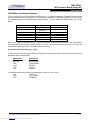
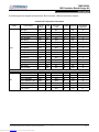
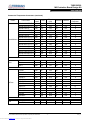
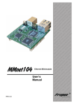
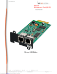
78Q2120C09
10/100BASE-TX Transceiver
MII Evaluation Board Design Kit
User Manual
UM 78Q2120C09 v1-2
April 2007
DESCRIPTION
The 78Q2120C09-DB is a design example for a
10/100BASE-TX Mbit/second Fast Ethernet MII
Interface adaptor. The 78Q2120C09 transceiver
provides the network physical interface and MII
(Medium Independent Interface) interface.
Teridian Semiconductor’s 78Q2120C09 is an autosensing, auto-switching 10/100BASE-TX Fast
Ethernet transceiver with full duplex operation
capability. The device interfaces directly to the
IEEE-802.3u MII port.
Full-featured MII
management functions are included along with an
extended register set. A five bit configurable PHY
address is provided for multiple PHY architectures.
The 78Q2120C09 interfaces to CAT5 UTP cable via
a 1:1 transformer.
The transceiver’s transmitter includes on-chip the
pulse shaper and low power line driver. The
receiver incorporates a sophisticated combination of
real-time adaptive equalization, an adaptive DC
offset adjustment circuit and baseline wander
correction. Smart squelch circuitry further improves
the receiver’s noise rejection. Full featured autonegotiation or parallel detect modes are supported.
Using 0.18µm CMOS technology, the 78Q2120C09
operates at +3.3V. Intelligent power management
and power down modes minimize power
consumption. The demo board requires operation
with a +3.3V power supply.
Design Kit contains:
√
√
√
√
√
78Q2120C09 MII Demo Board
Demo Board Parts List
P.C.B. Gerber Files
Demo Board schematic
78Q2120C09 Data Sheet
© 2007 Teridian Semiconductor Corporation, Proprietary and Confidential
Downloaded from Elcodis.com electronic components distributor
100Base-TX Interface
RJ45 Pin Assignment
Pin
Signal
1
TX+
2
TX3
RX+
4
N/C
MII:
Pin
5
6
7
8
Signal
N/C
RXN/C
N/C
Medium Independent Interface
Pin Assignment:
(40 Pin Male Subminiature D, 0.050)
Pin
Signal
Pin
Signal
1
+3.3V
21
+3.3V
2
MDIO
22
COMMON
3
MDC
23
COMMON
4
RXD3
24
COMMON
5
RXD2
25
COMMON
6
RXD1
26
COMMON
7
RXD0
27
COMMON
8
RXDV
28
COMMON
9
RXCLK
29
COMMON
10
RXER
30
COMMON
11
TXER
31
COMMON
12
TXCLK
32
COMMON
13
TXEN
33
COMMON
14
TXD0
34
COMMON
15
TXD1
35
COMMON
16
TXD2
36
COMMON
17
TXD3
37
COMMON
18
COL
38
COMMON
19
CRS
39
COMMON
20
+3.3V
40
+3.3V
-1-
Rev_1.2
78Q2120C09
10/100BASE-TX Transceiver
MII Evaluation Board Design Kit
User Manual
UM 78Q2120C09 v1-2
April 2007
MII ADAPTOR WITH 78Q2120C09
Switch Positions
The OFF switch position sets a logic level = “1” and conversely, the ON position sets a logic level = “0”.
Some DIP switch markings are different.
ON equals CLOSED.
OFF equals OPEN.
For normal operation switch SW2 should be set as follows:
ISO
ON
ISODEF
ON
TEST
ON
PAD4:0
PHY Address = 0, the 78Q2120C09 responds to all accesses
PHY Address = non-zero, the 78Q2120C09 responds only to its unique address
For normal operation the following SW1 switches should be set as follows:
N/U
OFF
(not used)
PCSBP
ON
PWRDN
ON
Switch SW1 positions ANEGA and TECH0:2 set the line interface technology capabilities.
Refer to the data sheet for a complete description.
For full Auto-Negotiation capabilities, set ANEGA and TECH0:2 to OFF.
Use With the Netcom Smart-Bits
The Netcom expects to be the master and defaults to 100BASE-TX Half-Duplex operation. To allow Fast-Ether
Windows to reconfigure the 78Q2120C09’s control register MR0 bits, set ANEGA and TECH0:2 all to OFF. If the
78Q2120C09’s technology pins are set to anything else, the 78Q2120C09 will disable some modes and prevent
the Netcom from reconfiguring the 78Q2120C09 and data errors may be observed.
After initialization the 78Q2120C09 defaults to 100BASE-TX Full-Duplex operation. When connected to another
fully capable transceiver, the transceivers will be in full-duplex mode. The default configuration of the Netcom is
100BASE-TX Half-Duplex operation. If data transfers were to commence, the Netcom would display Collision
errors (because it does not automatically read the transceivers and reconfigure).
If a transceiver is used which defaults to 100BASE-TX Half-Duplex operation, the 78Q2120C09 will adjust itself
for half-duplex operation (assuming the 78Q2120C09 is setup for the proper technologies).
To establish proper operation between the 78Q2120C09 and the Netcom, click on the “Options” button followed
by selecting “Full Duplex MII”. Repeat selecting “Full Duplex MII” twice to ensure that everything is configured
identically.
The 78Q2120C09 can be configured for half-duplex operation (ANEGA = ON and TECH0:2 = ON, OFF, ON) to
minimize incompatibilities with other transceivers and the Netcom.
© 2007 Teridian Semiconductor Corporation, Proprietary and Confidential
Downloaded from Elcodis.com electronic components distributor
-2-
Rev_1.2
78Q2120C09
MII Evaluation Board Design Kit
User Manual
fd
10/100Mbps Transformer Selection
The line interface for the 78Q2120C09 requires a pair of 1:1 isolation transformers. Integrated common-mode
chokes are recommended for satisfying FCC radiated EMI requirements. Additional filtering is not required with
the 78Q2120C09 due to internal waveform shaping circuitry. The line transformer characteristics are outlined
below:
Name
Turns Ratio
Open-Circuit Inductance
Leakage Inductance
Inter-Winding Capacitance
D.C. Resistance
Insertion Loss
HIPOT
Value
1 CT : 1 CT
350 µH (min)
See Note 1.
0.40 µH (max)
25 pF (max)
0.9 ohm (max)
1.1 dB (typ)
1500 Vrms
Condition
@ 10 mV, 10 KHz
@ 1 Mhz (min)
0 - 100 Mhz
Note 1: The receive line transformer’s Open-Circuit Inductance can be as low as 100 µH for the 78Q2120C09.
The 78Q2120C09 incorporates baseline wander correction circuitry which allows the receiver to track the
incoming data signal when there is excessive transformer droop.
For Commercial Temperature (0°C ~ 70°C)
Teridian Semiconductor has performed line testing with the following transformers and found their performance
acceptable with the 78Q2120C09:
Manufacturer
TDK
Bel-Fuse
Halo
Pulse
Valor
YCL
Part Number
TLA-6T103
S558-5999-46
TG22-3506ND
PE-68515
ST6118
20PMT04
The following transformers are low profile packages (0.100 in/2.5 mm or less).
TDK
TLA-6T118
Halo
TG110-S050
PCA
EPF8023G
© 2007 Teridian Semiconductor Corporation, Proprietary and Confidential
Downloaded from Elcodis.com electronic components distributor
-3-
Rev_1.2
78Q2120C09
MII Evaluation Board Design Kit
User Manual
fd
The following devices integrate the transformers, RJ45 connector, LEDs and termination resistors.
Commercial Temperature Connectors
Vendor
Pulse
Halo
Part number
Tab up
/down
LED
LED color
(L/R)
Shielding Lead-free
Compatible
Footprints *
J0011D21
J0011D21NL
J0011D21B
J0011D21BNL
J0011D21E
J0011D21ENL
J0011D01
J0011D01NL
J0011D01B
J0011D01BNL
J0012D21
J0012D21NL
J1011F01P
J1011F01PNL
J1011F21P
Down
Down
Down
Down
Down
Down
Down
Down
Down
Down
Down
Down
Up
Up
Up
No
No
Yes
Yes
Yes
Yes
No
No
Yes
Yes
No
No
Yes
Yes
Yes
N/A
N/A
G/Y
G/Y
G/G
G/G
N/A
N/A
G/Y
G/Y
N/A
N/A
G/Y
G/Y
G/Y
Yes
Yes
Yes
Yes
Yes
Yes
Yes
Yes
Yes
Yes
Yes
Yes
Yes
Yes
Yes
No
Yes
No
Yes
No
Yes
No
Yes
No
Yes
No
Yes
No
Yes
No
a
a
b
b
b
b
a
a
b
b
a
a
A
A
A
J1011F21PNL
Up
Yes
G/Y
Yes
Yes
A
HFJ11-2450EURL
HFJ11-2450EU-L11RL
HFJ11-2450ERL
HFJ11-2450E-L11RL
HFJT1-S003E-L11RL
HFJT1-S003-L11RL
Down
Down
Down
Down
Up
Up
No
Yes
No
Yes
Yes
Yes
N/A
G/G
N/A
G/G
G/G
G/G
No
No
Yes
Yes
Yes
Yes
Yes
Yes
Yes
Yes
Yes
Yes
e
f
c
d
B
C
HFJT1-S003
Up
No
N/A
Yes
Yes
D
© 2007 Teridian Semiconductor Corporation, Proprietary and Confidential
Downloaded from Elcodis.com electronic components distributor
-4-
Rev_1.2
78Q2120C09
MII Evaluation Board Design Kit
User Manual
fd
Commercial Temperature Connectors (continued)
Vendor
Part number
MIC24010-5101T-LF3
MIC24010-5104T-LF3
MIC24011-0101T
MIC24011-0101T-LF3
MIC24011-0101W-LF3
MIC24011-0104T
MIC24012-5101T-LF3
Wurth/Midcom MIC24012-5204T-LF3
MIC24013-5104T
MIC24018-5101T-LF3
MIC24019-0101T
MIC24111-0101T
MIC24111-0101T-LF3
MIC24412-0128T-LF3
Falco
BelFuse
TDK
Tab up
/down
Down
Down
Down
Down
Down
Down
Down
Down
Down
Down
Down
Up
Up
Up
LED
LED color
(L/R)
Shielding Lead-free
Compatible
Footprints *
No
No
Yes
Yes
Yes
Yes
Yes
Yes
Yes
Yes
Yes
Yes
Yes
Yes
N/A
N/A
Y/G
Y/G
Y/G
Y/G
G/G
G/G
G/Y
R/G
G/R
Y/G
Y/G
G/G
Yes
Yes
Yes
Yes
Yes
Yes
Yes
Yes
Yes
Yes
Yes
Yes
Yes
No
Yes
Yes
No
Yes
Yes
No
Yes
Yes
No
Yes
No
No
Yes
Yes
b
b
b
b
b
b
b
b
b
b
b
A
A
E
MIC24F11-0101T-LF3 Up
Yes
Y/G
No
Yes
F
LJ0004
LJ0012
Down
Down
No
No
N/A
N/A
Yes
Yes
Yes
No
a
a
LJ1011
Down
Yes
G/Y
Yes
No
d
SI-10021
SI-60002-F
SI-40139
SI-60001-F
SI-50170
SI-50170-F
SI-50177
SI-50177-F
SI-50193
SI-50193-F
SI-50196
Down
Down
Down
Down
Up
Up
Up
Up
Up
Up
Up
No
No
Yes
Yes
Yes
Yes
No
No
No
No
Yes
N/A
N/A
G/G
G/G
G/G
G/G
N/A
N/A
N/A
N/A
G/G
Yes
Yes
Yes
Yes
Yes
Yes
Yes
Yes
No
No
No
No
Yes
No
Yes
No
Yes
No
Yes
No
Yes
No
a
a
d
d
A
A
D
D
G
G
F
SI-50196-F
Up
Yes
G/G
No
Yes
F
TLA-6T704
Down
No
N/A
Yes
Yes
a
TLA-6T707
Down
No
N/A
Yes
Yes
a
© 2007 Teridian Semiconductor Corporation, Proprietary and Confidential
Downloaded from Elcodis.com electronic components distributor
-5-
Rev_1.2
78Q2120C09
MII Evaluation Board Design Kit
User Manual
fd
* Notes:
1. The letters stand for different footprint drawings
2. Lower case is for the tab-down version. Upper case is for tab-up version.
3. The compatible connectors are labeled with the same letter.
The above evaluations were performed using Netcom’s Smart-Bits Fast Ethernet Analyzer. The Teridian
Semiconductor 78Q2120C09 MII Adapter and Lancast Fast Ethernet Adapter were attached to the Netcom’s
Ports A & B respectively. Twisted pair Category 5 General Cable P/N 459360 was used to connect the two
transceivers. 100 Mbps performance was measured using cable lengths of both 12 inches and 115 meters. 10
Mbps performance was evaluated using 100 meters of Category 3 cable.
The Netcom was configured to use the Baseline Wander Packet file. Packet length was 1500 bytes.
All transformers listed above met or exceeded IEEE’s 802.3 Bit Error Rate requirements of 10-8.
© 2007 Teridian Semiconductor Corporation, Proprietary and Confidential
Downloaded from Elcodis.com electronic components distributor
-6-
Rev_1.2
78Q2120C09
MII Evaluation Board Design Kit
User Manual
fd
PCB Layout Considerations
The following recommendations enhance the 78Q2120C09’s performance while minimizing EMC emissions:
1.
2.
3.
4.
5.
6.
7.
8.
9.
10.
11.
12.
13.
14.
15.
16.
17.
18.
19.
20.
21.
22.
23.
24.
The transformer to transceiver signal traces must be 100 ohm differential transmission lines.
Place the termination network components near the input data pins of the transceiver or transformer.
Make all differential signal pairs short and of the same length.
Decouple the transceiver thoroughly with 0.01µf and 0.1µf capacitors.
Locate these decoupling capacitors as close as possible to the respective transceiver VCC and GND
pins.
All decoupling capacitor and transceiver VCC and GND connections should tie immediately to a VCC or
GND plane via with minimum trace inductance.
Total decoupling capacitance should be greater than the load capacitance that the digital output drivers
must drive.
Use low inductance, ceramic surface mount decoupling capacitors.
Use a multi-layer PCB with the inner layers dedicated to GND and VCC.
A single VCC and GND plane is recommended for optimum performance. The lowest possible series
impedance is required between the analog and digital VCC and GND pins respectively of the transceiver.
The outer layers of a 4 layer PCB are to be used for signal routing.
Place the highest speed signals on the layer adjacent to the GND plane.
Physically separate the analog signals from the digital signals by placing them on opposite layers or
routing them away from each other.
Additional component and solder side ground layers may be added for maximum EMC containment.
The GND plane should extend out to the transceiver side of the transformer. Remove the VCC and GND
planes from the line side of the transformer to the RJ-45 connector.
Do not allow the chassis ground plane to cross over the transceiver GND plane. Minimum separation
must accommodate over 1.5KV.
Provide onboard termination of the unused signal pairs in the CAT-5 cable.
Use a shielded RJ-45 connector with its case stakes soldered to the chassis ground.
Locate the transformer adjacent to the RJ-45 to minimize the shunt capacitance to the line.
Minimize RF current fringing by making the VCC plane 0.10 inch smaller than the GND plane. If multiple
transceivers are used, provide partitions in the VCC and GND planes between the analog sections.
Maintain the partition from the transformer up to the transceiver’s analog interface. Do not cross these
partitions with signal traces, in particular any digital signals from adjacent transceivers.
Add series resistors on all transceiver MII outputs to minimize digital output driver peak currents.
Minimize the use of vias when routing the analog signal traces.
Isolate the crystal and its capacitors from the analog signals with a guard ring.
The crystal compensation capacitor value (C11 & C12) must be selected to trim the oscillator’s frequency
to 25.0000 MHz ±50ppm. The optimum value will be layout dependent. A mere ±4pf can shift the
25MHz ±100Hz. The 25.0000 MHz ±50ppm is specified by the IEEE.
Note: System vendors need to select the proper crystal according to their applications, such as operating
environment, product lifetime, and etc since crystal aging, operating temperature, and other factors can
affect the crystal frequency tolerance.
© 2007 Teridian Semiconductor Corporation, Proprietary and Confidential
Downloaded from Elcodis.com electronic components distributor
-7-
Rev_1.2
78Q2120C09
MII Evaluation Board Design Kit
User Manual
fg
VCC
TXEN
TXCLK
TXER
TXD3
TXD2
TXD1
TXD0
VCC
R15
10K
0603
R5
RXCLK
RXER
RXD3
RXD2
RXD1
RXD0
RXCLK
RXER
RXD3
RXD2
RXD1
RXD0
100
R6
R7
R8
R9
R11
R13
100
100
100
100
100
100
TC
0603
RC
RE
R3
R2
R1
R0
0603
0603
0603
0603
0603
0603
MDC
MDIO
6
C10
0.1
0805
GND
VCC
0603
0603
0603
0603
0603
0603
0603
0603
8
7
6
5
4
3
2
1
10K
10K
10K
10K
10K
10K
10K
10K
24
25
19
20
21
22
18
17
/RST
RST
R18
R19
R20
R21
R22
R23
R25
R26
28
27
26
32
31
30
29
Use 33 ohm for maximum drive
MDC
MDIO
C3
0.1
0603
GND
C8
0.01
0603
GND
C9
0.01
0603
GND
PWRDN
7
ANEGA
TECH2
TECH1
TECH0
47
44
45
46
PCSBP
ISO
ISODEF
64
2
1
PHYAD4
PHYAD3
PHYAD2
PHYAD1
PHYAD0
12
13
14
15
16
TXEN
TXCLK
TXER
TXD3
TXD2
TXD1
TXD0
VCC
VCC
VCC
VCC
VCC
VCC
68 ohm Impedance Traces
TXEN
TXCLK
TXER
TXD3
TXD2
TXD1
TXD0
C2
0.1
0603
GND
C4
0.1
0603
GND
100 ohm Diff. Impedance Traces
TXOP
TXON
RXIP
RXIN
RXCLK
RXER
RXD3
RXD2
RXD1
RXD0
RPTR
CRS
COL
RXDV
LEDL
LEDTX
LEDRX
LEDCOL
LEDFDX
LEDBTX
LEDBT
MDC
MDIO
RST
PWRDN
ANEGA
TECH2
TECH1
TECH0
INTR
PCSBP
ISO
ISODEF
NC2
NC1
PHYAD4
PHYAD3
PHYAD2
PHYAD1
PHYAD0
CKIN
XTLP
XTLN
GND
C6
0.1
0603
GND
C7
0.1
0603
R1
49.9
1%
0603
R3
49.9
1%
0603
R2
49.9
1%
0603
R4
49.9
1%
0603
TXOP
TXON
52
51
RXIP
RXIN
50
Note: This demo
board schematic is
only applicable for
the 78Q2120C09
revision.
TXOP
TXON
RXIP
RXIN
RPTR
34
33
23
CRS
COL
RXDV
RXDV
40
39
38
37
49
36
48
LEDL
LEDTX
LEDRX
LEDCOL
LEDFD
LED100
LED10
LEDL
LEDTX
LEDRX
LEDCOL
LEDFD
LED100
LED10
VCC
R16
35
10K
0603
INTR
56
54
4
59
58
3
2
1
GND
J1
CON3
INTR
R24
CKIN
5.1K
0603
XTLP
XTLN
GND
Y1
GND
GND
GND
GND
GND
GND
GND
GND
60
55
53
42
10
9
5
3
9
10
11
12
13
14
15
16
U1
78Q2120C09-CGT
TSC
LQFP64
C5
0.01
0603
GND
61
62
SW1
GND
VCC
VCC
63
57
43
41
11
8
C1
0.1
0603
GND
C11
39PF
0603
25.000MHZ
50ppm
GND
C12
39PF
0603
GND
GND
VCC
10K
10K
10K
10K
10K
10K
10K
10K
0603
0603
0603
0603
0603
0603
0603
0603
16
15
14
13
12
11
10
9
R27
R28
R29
R30
R31
R32
R33
R34
1
2
3
4
5
6
7
8
SW2
GND
78Q2120C09 Evaluation Board Schematic – MII Interface
© 2007 Teridian Semiconductor Corporation, Proprietary and Confidential
Downloaded from Elcodis.com electronic components distributor
-8-
Rev_1.2
78Q2120C09
MII Evaluation Board Design Kit
User Manual
fg
VCC
GND
C14
0.01
0603
GND
100 ohm Diff.
Impedance Traces
T1
TXOP
TXOP
1
2
3
4
5
6
7
8
TXON
TXON
RXIP
RXIP
RXIN
RXIN
C19
10PF
0603
GND
TD+
TDCT
TDNC1
NC2
RD+
RDCT
RD-
RP
RN
C15
0.1
0603
GND
TN
R35
75
0603
16
15
14
13
12
11
10
9
TP
R36
75
0603
J24
J25
R39
75
0603
C16
0.01
1.5KV
1812
1
1
LEDRX
1
COL
1
FD
1
2
TLED
D3
D4
D5
LED100
1
68 ohm Impedance Traces
2
RLED
VCC
R42
R43
R44
R45
R46
R47
R48
2 CLED
2 FLED
680
680
680
680
680
680
680
D6
LED10
1
D7
2
HLED
2
SLED
R41
5.1K Use 1.5K - 10K
0603
0603
0603
0603
0603
0603
0603
0603
LED
J4
CON3
1
2
3
+3.3V
VEXT
VEXT
MH3
MH4
MTHOLE
1
1
MTHOLE
GND
MTHOLE
VCC
+3.3V
VIN
VCC
C17
0.1
0603
VCC
C18
10
0805
1
MH2
MTHOLE
CGND
J3
MDIO
MDC
RXD3
RXD2
RXD1
RXD0
RXDV
RXCLK
RXER
TXER
TXCLK
TXEN
TXD0
TXD1
TXD2
TXD3
COL
CRS
MDIO
MDC
RXD3
RXD2
RXD1
RXD0
RXDV
RXCLK
RXER
TXER
TXCLK
TXEN
TXD0
TXD1
TXD2
TXD3
COL
CRS
LED
10
MH1
RJ45
VCC
LED
100
LED10
D2
LED
LEDFD
LED100
LLED
LED
LEDCOL
LEDFD
2
LED
RX
LEDCOL
D1
LED
TX
LEDTX
LEDRX
R40
75
0603
1
2
3
4
5
6
7
8
9
10
CONNECT CGND TO
MOUNTING BRACKET
LK
LEDL
LEDTX
J2
J27
J28
R37
75
0603
Optional ESD noise suppression
LEDL
R38
75
0603
J2R
TLA-6T118LF
TDK
SMT16
VCC
C20
10PF
0603
GND
TX+
TXCT
TXNC4
NC3
RX+
RXCT
RX-
1
C13
0.1
0603
100 ohm Diff. Impedance Traces
GND
GND
1
2
3
4
5
6
7
8
9
10
11
12
13
14
15
16
17
18
19
20
21
22
23
24
25
26
27
28
29
30
31
32
33
34
35
36
37
38
39
40
MII
INTERFACE
FCN-238P040-G/F
FUJITSU
78Q2120C09 Evaluation Board Schematic – Line Interface
© 2007 Teridian Semiconductor Corporation, Proprietary and Confidential
Downloaded from Elcodis.com electronic components distributor
-9-
Rev_1.2
78Q2120C09
MII Evaluation Board Design Kit
User Manual
78Q2120C09 MII Demo Board Parts List
QTY REFERENCENUMBER
1 U1
2
1
1
7
6
7
7
2
18
4
2
2
4
9
1
1
1
1
1
1
SW1,SW2
T1
Y1
D1,D2,D3,D4,D5,D6,D7
R35,R36,R37,R38,R39,R40
R5,R6,R7,R8,R9,R11,R13
R42,R43,R44,R45,R46,R47,R48
R24,R41
R15,R16,R18,R19,R20,R21,R22,
R23,R24,R25,R26,R27,R28,R29,
R30,R31,R32,R33,R34
R1,R2,R3,R4
C19,C20
C11,C12
C5,C8,C9,C14
C1,C2,C3,C4,C6,C7,C13,C15,C17
C10
C16
C18
J2
J3
DESCRIPTION
IC, 10/100Mbps LAN
Transceiver
DIP SWITCH, 8 POS
XFRM, 10BaseT/100BaseTX
CRYSTAL, 25.000MHZ
LED
RES, 75
RES, 100
RES, 680
RES, 5.1K
RES, 10K
RES, 49.9, 1%
CAP, CER, 10PF
CAP, CER, 39PF
CAP, CER, 0.01UF
CAP, CER, 0.1UF
CAP, CER, 0.1UF
CAP, CER, 0.01UF, 1.5KV
CAP, CER, 10UF, 10V
CONN, RJ45, SHIELDED
CONN, MALE, 40 PIN
P.C.B.
© 2007 Teridian Semiconductor Corporation, Proprietary and Confidential
Downloaded from Elcodis.com electronic components distributor
- 10 -
PARTNUMBER
78Q2120C09-CGT
PACKAGE
LQFP64
MANUFACTURER
TSC
TLA-6T118LF
ECCM1-25.000MHZ
LU20125
SMT16
ECCM1
R/A
CC0603
CC0603
CC0603
CC0603
CC0603
TDK
ECLIPTEK
LUMEX
C1608Y5V1H104Z
C2012Y5V1H104Z
558342-1
FCN-238P040-G/F
CC0603
CC0603
CC0603
CC0603
CC0603
CC0805
CC1812
CC0805
Optional
TDK
TDK
AMP
FUJITSU
Rev_1.2
78Q2120C09
MII Evaluation Board Design Kit
User Manual
Top Silkscreen
© 2007 Teridian Semiconductor Corporation, Proprietary and Confidential
Downloaded from Elcodis.com electronic components distributor
- 11 -
Rev_1.2
78Q2120C09
MII Evaluation Board Design Kit
User Manual
Top Layer
© 2007 Teridian Semiconductor Corporation, Proprietary and Confidential
Downloaded from Elcodis.com electronic components distributor
- 12 -
Rev_1.2
78Q2120C09
MII Evaluation Board Design Kit
User Manual
VCC Layer
© 2007 Teridian Semiconductor Corporation, Proprietary and Confidential
Downloaded from Elcodis.com electronic components distributor
- 13 -
Rev_1.2
78Q2120C09
MII Evaluation Board Design Kit
User Manual
Ground Layer
© 2007 Teridian Semiconductor Corporation, Proprietary and Confidential
Downloaded from Elcodis.com electronic components distributor
- 14 -
Rev_1.2
78Q2120C09
MII Evaluation Board Design Kit
User Manual
Bottom Layer
© 2007 Teridian Semiconductor Corporation, Proprietary and Confidential
Downloaded from Elcodis.com electronic components distributor
- 15 -
Rev_1.2
78Q2120C09
MII Evaluation Board Design Kit
User Manual
Bottom Silkscreen
No responsibility is assumed by TERIDIAN SEMICONDUCTOR CORPORATION for use of this product or for any infringements of patents
and trademarks or other rights of third parties resulting from its use. No license is granted under any patents, patent rights or trademarks of
Teridian Semiconductor Corporation, and the company reserves the right to make changes in specifications at any time without notice.
Accordingly, the reader is cautioned to verify that the data sheet is current before placing orders.
Teridian Semiconductor Corporation, 6440 Oak Canyon, Irvine, CA 92618-5201, (714) 508-8800, FAX: (714) 508-8877
http://www.teridian.com
© 2007 Teridian Semiconductor Corporation, Proprietary and Confidential
Downloaded from Elcodis.com electronic components distributor
- 16 -
Rev_1.2