1
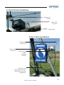
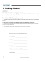
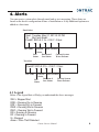
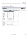
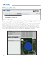
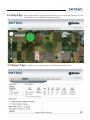
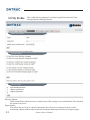
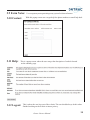
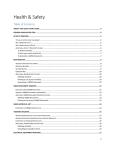
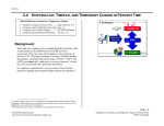
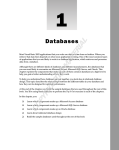
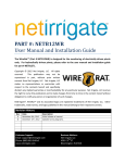
Operators Manual Ontrac Remote Management Ontrac CELL To Make The Most of Your 24 Hours Table of Contents I. System Safety.............................................................................................................1-2 2. Ontrac Cell at a Glance.............................................................................................3-4 3. Getting Started.............................................................................................................5 4. Alerts and Legend........................................................................................................6 5. Ontrac Website.......................................................................................................7-14 How to Log into website..............................................................7 Summary Page............................................................................8 Summary Site Details.................................................................9 Summary Site Setup.................................................................10 Summary Site Notes and Control.............................................11 Map and Report Page...............................................................12 My Profile..................................................................................13 Farm Notes, Contact, Help and Logout...................................14 6. System Maintenance..................................................................................................15 1. System Safety When towing a System from field to field, avoid ditches, rough terrain, overhead power lines, etc. The Ground Wire MUST be re-attached to the Ground Rod and checked for electrical integrity each time the System is towed. Avoid any bodily contact with high pressure water streams from Sprinklers and End Guns. Keep away from fields where the System is chemigating. Make sure the applied chemical and water does not blow or drift past the area of intended operation. A Check Valve must be installed between the Pivot Center and the Pump to prevent the mixture of water and chemical from siphoning back into the irrigation water source. Comply with all local, state, and federal regulations. Do not oversize Fuses. Fuses are sized for a specific circuit. It is very important to make sure you have the proper fuse size in place before initially starting the System and when replacing Fuses. Do not operate System when temperatures are below 40°F (4.5°C). This can cause structural damage to the System. 1 Ontrac Owners Manual In most states it is unlawful to spray water on state and county roadways. This is a serious hazard and must not be allowed. If your System is equipped with any Auto-Stop or Auto-Reverse Mechanism, make sure they are working correctly and a Tower Barricade is properly installed as per this manual. Reinke disclaims any and all liability (including any liability created pursuant to the Irrigation Systems Warranty) with regard to damage to the Irrigation System, or to other property, or personal injury or death, caused by improper installation or maintenance of Reinke-supplied Tower Auto-Reverse or Auto-Stop Switches or Tower Barricades, or by use of customersupplied Barricades. Driveshafts may start without warning. Keep away from Driveshafts to prevent clothing or limbs from being entangled, resulting in severe injury. Do not endanger your own life and possibly the lives of others by being negligent. Be aware that the system may start automatically, depending on how your system is setup, monitored, and controlled. The Reinke Electrogator II System is designed with many electrical and mechanical safety features. However, each operator must read and understand this and all other accompanying owners manuals for the safe and efficient operation of your Reinke Electrogator II System. If this System is operated incorrectly, it can pose a safety threat to the operator and others. The following is a list of safety operating tips which all service and operating personnel must read and understand. The Tower Steps have been provided for access to the Tower Control Boxes only. They are not intended for access to the Span. For instance, should the Sprinkler Heads require service, use a ladder to reach them from the ground. The Safety Alert Symbol is displayed many places throughout this manual and on your System to indicate when there is a potential for Personal injury. Throughout this manual and on System Decals, the words “DANGER”, “WARNING”, and “CAUTION” are used with the Safety Alert Symbol to alert the operator of potential hazards. DANGER” identifies the most serious hazards. “DANGER” or “WARNING” safety signs identify specific hazards. “CAUTION” signs identify specific safety instructions. The movement of an Electrically Powered, Gear-Driven, Irrigation System is relatively slow. Moving parts are exposed and may present a potential hazard. Therefore, keep all equipment, vehicles, people, etc., out of the System’s path. DO NOT attempt to perform any maintenance procedures until the Main Control Panel Disconnect Switch and all Pump and other Disconnect Switches are locked in the “OFF” position. Electrical component troubleshooting and replacement should be performed by a certified Service Technician to ensure builtin safety features remain intact. This also ensures System remains compliant with the National Electric Code and the Manufacturers Specifications. Replace all Protective Guards and Shields before restoring power to the System. Exercise caution when handling fuel near Systems equipped with Combustion Enginedriven Generators and Pumps. If you attempt to repair your System and are uncertain of your methods, contact an authorized Service Person. K e e p a w a y f ro m t h e S y s t e m d u r i n g thunderstorms or other severe weather conditions. The Center Pivot is grounded and the System is probably the highest object in the field, making it a good lightning receptor. Be sure Protective Guards are installed on all Belts and Driveshafts of Ancillary Equipment such as Combustion Engines, Electric Motors, Pumps, etc. If you suspect a short circuit or the System is not working correctly, do not touch the System and keep others away from it. Call your Service Technician. Electrical component troubleshooting and replacement should be performed by a certified Service Technician to ensure builtin safety features remain intact. This also ensures System remains compliant with the National Electric Code and the Manufacturers Specifications. Do not allow anyone to ride or climb on the System unless they are qualified and required to do so for maintenance purposes. Ontrac Owners Manual 2 2. Ontrac Cell at a Glance Ontrac Cell - base unit Enclosure Lid LCD onboard setup screen GPS Port Control board port Digital Inputs Antenna Connector Analog Inputs Cellular Modem Safety Disconnect Switch 2.1 How it works The Ontrac Cell communicates through a cellular network to an Ontrac server where the data is stored. This information is displayed on your website for monitoring and control of your irrigation system. You can access the secure website anytime, anywhere; using any internet enabled device such as tablets, smartphones, laptops and desktop computers. Ontrac cell can easily keep you in touch with you and your irrigation systems through the critical system alerts this product offers. 3 Ontrac Owners Manual 2.2 Span Mount Installation Antenna and mount Ontrac Cell base unit Span Mount Pivot Center installation Cell antenna and mount Ontrac Cell base unit. Optional pivot center mounting bracket. Electrical Cord connecting to the main control panel electrical components. Ontrac Owners Manual 4 3. Getting Started Activation To activate the wireless service plan, you need: A wireless services agreement provided by an authorized Reinke dealer. The Reinke dealer can help you successfully activate your Ontrac Cell device. To use Ontrac Cell with your phone, you need: To enable text messaging with your cell phone provider and or enable internet access on compatible devices. To use Ontrac Cell with your computer, tablet or smartphone, you need: Internet Access; and at least one of the following internet browsers: Internet Explorer 9 or greater, Firefox 11, Google Chrome 26x. Your username and password, and passcode provided at time of activation Record your account information below: Account Name: ___________________________ Username: ______________________________ Password: _______________________________ 5 Digit Passcode: _________________________ Cell Modem Serial Number: RNKE____________ Field Location: ____________________________ 5 Ontrac Owners Manual 4. Alerts You can receive system alerts through email and or text messaging. These alerts are based on the device configuration at time of installation or if any additional options are added at a later time. Email Alert Sent: Tuesday, May 21, 2013 2:33 PM To: My Farm Email Field#1 SW!>S 0.1h –214.0°- 0.0psi Site Name GPS Location Current Status Current System Duration of Last Water Pressure Last Status Status Text Alert Field#1 SW!>S 0.1h –214.0°- 0.0psi Site Name GPS Location Current Status Current System Duration of Last Water Pressure Last Status Status 4.1 Legend Below is the legend that will help you understand the above messages. SW! = Stopped Wet RDR = Running Dry in Reverse RDF = Running Dry in Forward RWR = Running Wet in Reverse RWF = Running Wet in Forward RR = Running in Reverse RF = Running in Forward S = Stopped Alarm = Wire Theft Detected Ontrac Owners Manual 6 5. Ontrac Website 5.1 How to Log into the Ontrac website Make sure you have your username and password handy that you created during activation. 1. Go to www.ontracbyreinke.com 2. Type in your username in the text box provided on the screen 3. Type in your password in the text box provided on the screen 4. Click when finished and you’ll enter your Ontrac website. (If you check the remember me box the next time you go to the website it will automatically remember your login name and password.) Please use caution when using the remember me option as this will allow access to any one using your phone. 1 2 3 7 Ontrac Owners Manual 5.2 Summary Page A. Summary Page: Lists all systems being monitored. All blue/purple text are links to other pages. site - ivr: Unique name of pivot. Current Status: Displays current status of your system with both a symbol as well as a 1 or 2 letter code. psi: When a pressure transducer is used this shows actual system pressure. GPS: This shows the location of the system in degrees control: Depending on how the unit is equipped, This will allow you to do functions such as stop, stop by position, notify on position and set a daily schedule . wet/run hours: Total hours the pivot has ran wet (with water) since the viewing data starting date at the bottom 24h rain: The amount of rain that has fallen in the last 24 hours if this option is installed on the device. By clicking on (site-ivr or current status) blue text headers, changes the order in which this information is displayed on this page and by clicking on the blue text within the columns takes the user to more pages that show further detail of each system as shown on the next few pages. Ontrac User Manual 8 5.3 Summary-Site-Details: Below is an example of a page the user will see by clicking on one particular pivot system. On this page the screens visible can vary in number and content depending upon the options installed on each system. 9 Ontrac Owners Manual 5.4 Summary-Site-Setup: By clicking on the setup, site notes and control tabs of the details screen the user will go into even further detail as shown next. The headers will show path to screen shown. Ontrac Owners Manual 10 5.5 Summary-Site-Notes: Add your notes for the system here. Summary-Site-Control: The control screen is optional and not standard on the system. All buttons and displays are also optional on the control screen. If purchased at the time of setting up the system these buttons will be available, if not, they won’t be available until they are purchased and installed by your dealer. These buttons control the system remotely for starting, stopping the system and can also be used to schedule different commands to be carried out at specific times and dates by pushing the schedule button as shown. Each command sent to the system using the stop or start buttons will be on the report screen shown above right. Every command should be followed by a confirmation message of successful or delivery failure via text or e-mail depending on system set-up. Successful means the command was received failure means it was not received. If a failure happens try one more command before calling the dealer for support. 11 Ontrac Owners Manual 5.6 Map Page: Shows topical map of your area and locations of your systems this tab also gives the user the ability to save different maps and locations. C. Reports: This is where the user can set up different reports needed about any or all pivots in the field. 5.7 Report Page: Clicking on run report produces a .pdf file that could be saved. Ontrac Owners Manual 12 5.8 My Profile: This is where the user changes: User Name/Login Name, Password, Time, Message Options and Pager Options. [email protected] [email protected] [email protected] Message Options: When checked these allow the user to control some of the messages received and when. If not checked `` the option is not active. Pager Options: This allows the user to be in control of personnel who will receive messages from the system, deselecting a phone number/name deactivates the phone number/person from receiving messages. 13 Ontrac Owners Manual 5.9 Farm Notes: 5.10 Contact: 5.11 Help: User can put any notes pertaining to any system for future reference. With this popup screen user can get help line phone numbers or email help desk. This is a popup screen where the user can get the description of each tab located on the summary page. 5.12 Logout: This is where the user logs out of the website. The user should always do this when finished working on the website to insure privacy. Ontrac Owners Manual 14 6. System Maintenance 1. Year End -Winterization a. Disconnect the battery from the electronic board if there is no solar panel present. b. Remove the battery from the unit if winter temperatures reach 32° Fahrenheit or lower. c. Store battery above 32° degrees Fahrenheit to help preserve battery life; also if system will be idle for more than a 2 month period regardless of Solar Panel installation. 2. Clean Solar Panel if option is installed. In the spring, mid summer and fall using a damp soft cloth to remove any residue buildup as residue can significantly reduce the solar panel performance. 15 Ontrac Owners Manual Cellular Technology Onboard Setup Ideal for frequent reporting and control functions. Allows for quick response times through the cellular networks. This device allows for quick setup without the need for external computers. You can quickly change input settings and reporting frequency easily with the onboard LCD and setup menus. Equipment Compatibility Economic Value Provides remote monitoring and control on all brands of center pivots as well as other irrigation equipment. Ontrac Cell will provide years of reliable monitoring and control and the performance the user is looking for at an affordable cost of ownership. It is easy to maintain and scalable for future sensor integrations. Reinke Manufacturing Company, Inc. 1040 Road 5300 • P.O. Box 566 Deshler, Nebraska 68340 U.S.A Telephone: 402-365-7251 • Fax: 402-365-4390 Grower’s Hotline: 866-365-7381 www.reinke.com Create reports, control your system, or view extensive history via the internet. Control your system via tablet, smart phone, or any secure internet connection. In keeping with our mission, “to exceed our customers' expectations of quality, service and innovation,” Reinke Manufacturing Company may periodically decide it is most beneficial to our customers to make updates or changes to various products and options without delay. These changes may not always be fully reflected in the photographs, information and/or specifications presented in this brochure. Your local Reinke dealer continues to be your best source for the most current information. Reinke Manufacturing Company, Inc. reserves the right to discontinue models at any time, or to change specifications, design, or accessories without notice and without incurring obligation. #117806 Rev. (05-13) www.reinke.com