1
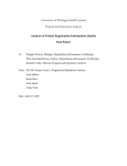
1
TE
RI
AL
Databases
MA
Most Visual Basic 2005 applications that you write use data in some form or fashion. Where you
retrieve that data from depends on what your application is doing. One of the most common types
of applications that you are likely to write is a database application, which retrieves and processes
data from a database.
TE
D
Although there are different kinds of databases and different manufacturers, the databases that
you are most likely to encounter are Microsoft Access, Microsoft SQL Server, and Oracle. This
chapter explores the components that make up each of these common databases at a high level to
help you gain a better understanding of how they work.
GH
To help you understand how databases are put together, you look also at relational database
design. This topic describes the relationships between the different tables in your database and
how they can be designed for optimal performance.
PY
In this chapter, you:
RI
At the end of the chapter, you build the sample databases that are used throughout the rest of this
book. You’ll be using these databases to perform the Try It Out exercises in each of the chapters.
Learn which components make up a Microsoft Access database
❑
Learn which components make up a Microsoft SQL Server database
❑
Learn which components make up an Oracle database
❑
Learn about relational database design
❑
Build the sample databases used throughout the rest of this book
CO
❑
Chapter 1
Access Databases
Access databases are common and can be found on most computers, especially if the sample databases
were installed along with Microsoft Access as a standalone product or as part of Microsoft Office.
People use Access databases for a variety of reasons but mainly because they are standalone databases,
meaning that you can create an Access database and then send that database to someone else who, if he
or she has Microsoft Access installed, can open and use your database. These databases are easy to use,
and Access provides many wizards to help you create a functional database in no time at all.
The database engine for Access is the Microsoft Access program MSACCESS.EXE. This database engine
can create, open, and edit Access databases and manage the components that make up the database. The
database engine is responsible for all the work that controls the database and the data contained in it.
You can run this program by clicking Start on the taskbar and then clicking Run. In the Run dialog
box, enter MSACCESS and click OK. Microsoft Access starts, and depending on which version of
Microsoft Access you have, you may be prompted with a dialog box to open or create a new database.
The bottom line is that you can see the database engine at work and the user interface that it provides.
Although an Access database may look simple at first glance, it contains a lot of components, typically
referred to as objects. All you see as a user is a database file that you can copy and distribute through a
variety of channels. The brains behind the actual database itself is the database engine.
In this section, you explore some components that make up an Access database to gain a deeper
understanding and appreciation for the complexities that make up an Access database.
Database file
An Access database consists of one complex file that stores the various objects that make up the database.
You have probably seen the classic sample database Northwind.mdb. When you open this database, you
can view the tables, queries, forms, and reports. These are some of the objects contained in this database
file and are controlled by the database engine.
Access database files have an .mdb file extension and each database can contain tables, queries, forms,
reports, pages, macros, and modules, which are referred to as database objects. That’s a lot of information
in one large file, but Microsoft Access manages this data quite nicely.
Forms, reports, pages, macros, and modules are generally used to enable users to work with and display
data contained in the database. You will be writing Visual Basic 2005 applications to do this, so the only
database objects you’re really concerned about at the moment are tables and queries.
Tables
A table contains a collection of data, which is represented by one or more columns, and one or more rows
of data. Columns are typically referred to as fields in Microsoft Access, and the rows are referred to as
records. Each field in a table represents an attribute of the data stored in that table. For example, a field
named First Name would represent the first name of an employee or customer. This field is an attribute
of an employee or customer. Records in a table contain a collection of fields that form a complete record
of information about the data stored in that table. For example, suppose a table contains two fields, First
2
Databases
Name and Last Name. These two fields in a single record describe the name of a single person, as illustrated in Figure 1-1.
Figure 1-1
Queries
A query in a database is a group of Structured Query Language (SQL) statements that enable you to
retrieve and update data in your tables. Queries can be used to select or update all the data in one or
more tables or to select or update specific data in one or more tables.
SQL enables you to insert, update, and delete data in a database. Microsoft Access provides wizards and
visual tools that enable beginning programmers to write queries without having to know SQL.
Using database query objects can make your Visual Basic 2005 code simpler because you have fewer SQL
statements included in your code. Database query objects can also make your programs faster because
database engines can compile queries when you create them, whereas the SQL statement in a Visual Basic
2005 program needs to be reinterpreted every time it’s used. They also provide ease of maintenance
because changing a query in your database affects only the database and not your compiled program,
which may have been distributed to one or more users.
To understand the implications that queries can have on your programs, you need to learn some basic
SQL, which you do in Chapter 4.
SQL Ser ver Databases
A SQL Server database is more complex than an Access database and the actual database engine for SQL
Server is made up of multiple components. Also, unlike in an Access database, you cannot simply copy a
SQL Server database file and distribute it because SQL Server databases consist of multiple files.
Procedures must be followed before you can copy and distribute the database files for a SQL Server
database.
SQL Server comes in several editions, such as Microsoft SQL Server 2005 Express, Standard edition, and
Enterprise edition. However, the components that make up the SQL Server database engine are virtually
the same for all editions.
Many components, other than the database engine and database files, make up SQL Server. These
include such components as Replication, Data Transformation Services (DTS), Analysis Services, Meta
Data Services, and English Query. However, those components are beyond the scope of this book, as you
will be focusing your attention on the actual objects that make up a SQL Server database.
3
Chapter 1
SQL Server is a relational database consisting of many components, each of which contains multiple
objects. In the following sections, you examine the main objects that make up a SQL Server database.
While you will not examine each and every object of a database, rest assured that what you do learn here
will serve you well, laying the foundation for what you will be doing throughout the rest of this book.
A SQL Server database consists of at least two files: a data file and a log file. The data file contains all the
data that makes up a SQL Server database, such as tables, indexes, and stored procedures. You examine
these objects shortly. The log file contains transaction logs, which are records of changes made to the
database.
When you initially create a SQL Server database, the data file and log file are created by SQL Server; the
data file has an .mdf extension and the log file has an .ldf extension. As your database grows and you
run out of room on the hard drive, your database administrator may create a secondary data file on a
separate hard drive. It will typically have an .ndf file extension. Creating a secondary data file for a
database typically happens only with large enterprise databases, as most hard drives today can hold
multiple database files on a single drive, given the drives extremely large capacity.
Data files
The data file contains multiple objects that make up a database. Table 1-1 lists the various objects that
make up a database and are contained in the data file. While you will not be exploring each of these
objects in detail, it is helpful to know that they exist and what they do.
Table 1-1: SQL Server Data File Objects
4
Object
Description
Tables
Contains the data in a database, organized in a row-column
format.
Keys
Primary keys provide a unique value for each row of data in a
table. Foreign keys provide a relationship between two tables
using a column in one table and the primary key in another table.
Indexes
Provides pointers to rows in a table in a similar fashion that the
index in this book provides pointers to specific topics.
Constraints
Provides a means by which you can enforce the integrity of a
database, such as not allowing a column to contain a NULL value.
Stored Procedures
A single SQL statement or group of SQL statements
compiled into a single execution plan.
Views
A SQL SELECT statement that returns a virtual table.
Triggers
A special class of stored procedures that are automatically
executed when an Insert, Update, or Delete statement
is executed against a table.
Defaults
A default value that is inserted into a column in a table when no
value is supplied.
Databases
Object
Description
User-Defined Functions
A group of SQL statements that can be encapsulated into a
subroutine that can be called by views and stored procedures.
User-Defined Data Types
User-defined data types are based on system data types and
enable you to create a data type with attributes that can be
applied to all your tables.
User
Identifies a user with a database.
Roles
A group containing certain permissions in the database to
which you add users, effectively assigning the same permissions
to each user.
Tables
Tables are core objects that exist in the data file and contain information about your business. For example,
you could create an employee table like the one shown in Figure 1-1 that contains information about each
employee in your organization.
Each table that you define is made up of columns and rows. Each column represents an attribute about
the information stored in your table, such as an employee’s first or last name. Collectively, the columns
form a row in your table that represents a single occurrence of the information that the table represents.
(Refer to the Employees table in Figure 1-1.)
Keys
Each table in your database usually, but not necessarily, has a column that uniquely identifies each row
of data with a primary key. No two rows in a table can contain the same primary key, and SQL Server
enforces this rule. Primary key columns are usually defined using a globally unique identifier (Guid),
which is a unique value generated based on internal values in your computer. No two computers will
ever generate the same unique identifier.
Primary keys may also contain other values such as an employee’s employee number, which could consist
of alpha and numeric characters. Also, primary key columns cannot contain NULL values. A NULL value is
one missing: it does not exist.
When a primary key is created on a table, SQL Server automatically creates a unique index for the primary
key on the table. Creating a unique index ensures that no two primary keys can contain the same value.
Indexes are covered in detail in the next section. Using the index on the primary key column provides fast,
efficient access to the data when using the primary key to access data in a table.
Foreign keys point to the primary key in another table. A foreign key in one row of a table points to an
exact row of data in another table. A foreign key value cannot be inserted into a table if the row of data
that it is pointing to in another table does not exist. This is just one of the constraints placed on foreign
keys that help ensure referential integrity.
Referential integrity enforces the defined relationships between tables when records are inserted or
deleted. You cannot insert a foreign key value for a row of data that does not exist in another table.
Referential integrity also prevents you from deleting a row of data that is referenced by a foreign key. To
5
Chapter 1
do so, you must first delete the row of data containing the foreign key or update the column using a
NULL value. Only then are you able to delete the row containing the primary key.
Referential integrity is based on the relationship between foreign and primary keys and ensures that key
values are consistent across all tables. Referential integrity is automatically enforced by SQL Server and
prevents a user from updating a primary or foreign key in a manner that would break the integrity of
the data.
Indexes
An index is an object associated with tables and is built using one or more columns from a table. An
index stores information from columns (usually primary and foreign key columns) and the exact
location of that data within the table. Thus, using an index to access information in the table is very
efficient, as SQL Server will use the information contained in the index to find the exact location of the
row of data that you want retrieve or update.
SQL Server contains two main types of indexes: clustered and non-clustered.
Clustered indexes sort the data in the table rows by key, providing an efficient means of accessing data in
the table. However, because a clustered index sorts the data in the table, a table can contain only one
clustered index. You can think of a clustered index like a phone book. The columns that define the index
(for example, the last name followed by an initial) are used to sort the table rows. A clustered index
stores the data rows of the table in the bottom leaf of the index. This means that the index consists of the
index entries pointing to each row of data, and the data rows are stored at the end of the index.
Non-clustered indexes store the keys of the table in the index and contain pointers to where the data
actually resides in the table. The pointer in a non-clustered index is called a row locator because it actually
locates the row of data in the table.
Indexes can be unique or not. Unique indexes unique do not allow duplicate keys (keys that contain the
same data value), and indexes that are not defined as unique can contain duplicate keys. Index keys
should not be confused with primary keys in a table. An index key can be generated for any column in a
table that is used to access the data in the table.
The last index that I want to cover is the full-text index. This type of index is used on columns that contain
the TEXT data type. This is a data type that can store large amounts of data, up to 2 gigabytes worth. This
index enables you to search through the text in a column containing this data type for specific keywords.
Stored procedures
A stored procedure is a single SQL statement or group of SQL statements compiled into an execution plan
and stored under a unique name in the database. It is executed as a unit. A stored procedure can have
multiple SQL statements to perform such tasks as selecting data from one table and updating data in
another table.
Stored procedures increase application performance in a couple of ways. First, they enable fewer SQL
statements to be transmitted across the network, as you send only the name of the stored procedure and
any parameters it may require.
6
Databases
Second, stored procedures are similar to procedures and functions in other programming languages, as
they can contain input and output parameters and can return values. They use logic to control the flow
of processing, and numerous functions and SQL statements can be used in stored procedures.
You can use stored procedures to execute routine functions, such as selecting, inserting, updating, and
deleting data. A single stored procedure can be executed by multiple applications, thus providing code
reuse. You learn more about stored procedures in Chapter 9.
Views
A view is like a virtual table containing data from one or more tables. A view is stored in the database as
the actual SQL statements that are contained in the view, such as a stored procedure. When the view is
referenced, the virtual table is created using the SQL statements that are contained in the view.
Views are generally used to enable users to see data from multiple tables in one view, thereby giving the
illusion that the data exists as one table or group of data. This provides a couple of benefits. First, by
providing the impression that all of the data is in one table, the complexities of the database are hidden
from the user. Second, it provides a security mechanism in that you can grant a user access to the view
but not to the actual tables from which the view is derived, and you can limit the data a user sees.
Because a view is like a virtual table, you can execute SQL SELECT statements against a view, thereby
selecting only the data from the view that you need to see. You can also limit the results by using a SQL
Where clause and order the results using a SQL Order By clause. You learn more about these basic
SQL clauses starting in Chapter 4 and more about views in Chapter 9.
Log files
Each database that you create has its own transaction log. The transaction log contains transactions that
have been applied against your database. A transaction is the execution of a group of SQL statements as
one logical unit of work. SQL Server automatically manages transactions in the transaction log, generating
a before-and-after picture of the data in a table that is changed. This means that you can execute an
update query to update a row of data and SQL Server logs a record of the data before it was changed and
after it was changed. This allows for backward and forward recovery of the data in your database.
SQL Server manages transaction logging automatically. You can, however, use transactions in your
stored procedures to perform automatic recovery of the data that your stored procedures changed. You
can also use transactions in the ADO.NET classes that provide data access to your database. Transactions
are covered in more depth in Chapter 11.
Oracle Databases
Just as SQL Server databases are more complex than Access databases, Oracle databases are more complex
than SQL Server databases. Because Oracle was designed to be platform independent, its architecture is
more complex, and a single database in Oracle consists of more files than a SQL Server database.
Oracle comes in multiple editions: Enterprise, Standard, and Personal. However, the database engine
components are virtually the same for all editions. Each edition supports features not found in the
previous edition. For example, the Standard edition supports multiple processors, whereas the Personal
edition does not. Likewise, the Enterprise edition supports transparent application failover support, but
the Standard edition does not.
7
Chapter 1
Oracle consists of many components in addition to the database engine, including components that
perform data analysis, help you manage XML and image data, manage applications and clusters, and
monitor and manage database performance. However, those components are beyond the scope of this
book, which focuses on the components that make up an Oracle database.
Because Oracle is a relational database, it contains numerous components, and each component contains
many objects. In this section, you look at the main objects that make up an Oracle database. While the
topics presented here provide only a cursory overview, this information will help you throughout the
rest of the book.
The following sections describe the five file types created when you create an Oracle database.
Data files
Data files are perhaps the most important files that make up your database and perhaps among the most
complex. When an Oracle database is created, a single data file is created. However, you can create multiple data files, and most typical production databases contain at least two data files.
Data files are complex because they contain the various objects that make up your database. In Oracle terminology, these objects are known as segments. Because of the complexities of an Oracle data file, Table 1-2
contains only a partial list of the various objects, which you can compare to SQL Server data files.
Table 1-2: Oracle Data File Objects
8
Object
Description
Tables
Contains the data in a database, organized in a row-column format.
Keys
Primary keys provide a unique value for each row of data in a table.
Foreign keys provide a relationship between two tables using a
column in one table and the primary key in another table.
Indexes
Provides pointers to rows in a table similar to the fashion that the
index in this book provides pointers to specific topics.
Constraints
Provides a means by which you can enforce the integrity of a
database, such as not allowing a column to contain a NULL value.
Stored Procedures
A group of SQL statements compiled into a single execution plan.
Views
A SQL SELECT statement that returns a virtual table.
Triggers
A special class of stored procedures that are automatically executed
when an Insert, Update, or Delete statement is executed
against a table.
Functions
A group of SQL statements that can be encapsulated into a subroutine
that can be called by views and stored procedures.
User
Identifies a user with a database.
Roles
A group containing certain permissions in the database to which you
add users, effectively assigning the same permissions to each user.
Databases
Tables
Tables in Oracle perform the same function as they do in SQL Server — they contain information about
your business.
Keys
Keys in Oracle perform the same function as they do in SQL Server — they uniquely identify each row of
data in a table.
Indexes
Indexes in Oracle perform the same function as they do in SQL Server — they provide efficient access to
the data in your tables. However, Oracle contains many different kinds of indexes, as outlined in this
section.
B*Tree indexes contain four subtypes of indexes: The Index Organized Table index performs the same
function as the clustered index in SQL Server, which is to sort and store the data in the table by the
primary key.
The B*Tree cluster index, or index clustered table, stores blocks of data from multiple tables prejoined on the
keys. This enables you to select data using a clustered key (a primary and foreign key, for example) and
from the block that contains the rows related to that clustered key.
The reverse key index stores the keys in an index with the key value in reverse order, and is primarily used
on keys that contain sequential numbers. For example, suppose your primary keys started with a
sequential number of 1000. The next primary key would be 1001, and then 1002, and so on. The reverse
key index stores the primary keys in the index as 0001, 1001, and 2001. This allows the index keys to be
inserted into the index spread out over multiple blocks, thereby increasing the efficiency of your index.
The descending index enables you to store the primary key for a table in the index in descending
order. This is particularly useful when most of the data selected from a table is selected in descending
order.
Bitmap indexes use a single index entry to point to many data rows in a single table. This type of index
is particularly useful when indexing columns that contain simple values. For example, if a column
contains a value of 0 or 1 or a value of Y or N, this index can use a single index entry to point to all rows
of data that contain the specified value in your query.
A function-based index stores the computed results of a function in the index. A function is a subroutine
that can be used to encapsulate SQL statements that are repetitively executed and that return a result.
For example, the MAX function returns the maximum value in a column. Using a function-based index on
tables that rarely change can increase the performance of your queries.
The domain index is a user-defined index that you build yourself. You can then tell Oracle about the index
and the query optimizer will decide whether to use the index in your queries. This type of index is for
advanced users; in particular, database administrators.
The interMedia Text index enables the searching of keywords in large text fields. This type of index is
useful for specialized applications such as search engines that need to search huge amounts of text for
keywords entered by the user.
9
Chapter 1
Stored procedures
A stored procedure in Oracle is functionally equivalent to a stored procedure in SQL Server and stores a
single or group of SQL statements compiled into an execution plan.
Views
Views in Oracle perform the same function as they do in SQL Server and are like virtual tables containing
data from one or more tables.
Redo log files
Oracle’s redo log files are functionally equivalent to log files in SQL Server and enable you to recover
transactions made against the tables in your database. However, Oracle databases contain at least two
redo log files and can contain more. They are used in a round-robin fashion, whereby the first redo log
file is used until it gets full and then the second redo log file is used. When the second one is filled up,
the first redo log file is reused.
Control files
Oracle uses a single control file per database to tell the database engine where to find the other files, such
as the data and redo log files, associated with a database. It also contains other important information
about your database, such as the database name and the date and time the database was created. The
control file may also contain other information, such as the location of your archived redo log files.
Temp files
Temp files are used to store the intermediate results of large sort operations and large results sets from a
query. This provides efficient use of system resources, as smaller sort operations and results sets are
stored in the computer’s memory.
Password files
Information concerning password files is closely guarded at Oracle and rightly so given the security
concerns of corporations everywhere and the fact that Oracle is a very secure database. Be aware that
every database contains password files used to authenticate users performing administrative functions
against the database.
Relational Database Design
A relational database contains tables, rows, and columns that are related to one another. A relational
database that has been properly normalized will have more tables that contain fewer columns, rather
than a few tables containing lots of columns. A normalized relational database actually improves storage
efficiency and performance, even though it physically contains more tables than a non-normalized
database does. You will be reading about the process of normalization in the next section.
10
Databases
Each table in your database represents an object about your business, and each column in a table
represents an attribute of the object that the table represents. A row in the table represents a unique entry
for the object that the table defines.
To design a relational database, you must first identify all of the objects that will make up your database.
The term object is used to represent a set of information. You can also use the term entity in place of
object. An entity is an object that refers to a person, place, or thing. If you know that you will be building
an application that manages employees in your organization, you first identify which objects represent
the information about an employee. For example, an employee is an object and the employee’s manager
is an object.
Next, you want to identify which attributes make up the employee and manager objects. Tables 1-3 and 1-4
illustrate the attributes that have been identified for these objects.
Table 1-3: Employee Attributes
Attribute
Description
Employee Name
The name of the employee
Phone Number
The phone number for the employee
Location
The location where the employee works (for example, city, building, or
branch office)
Job Title
The job title of the employee
Table 1-4: Manager Attributes
Attribute
Description
Manager Name
The name of the manager
Phone Number
The phone number for the manager
Location
The location where the manager works (for example, city, building, or
branch office)
Now that you have identified all the attributes for these objects, you must identify the tables to which
these attributes should be assigned. You can begin by defining the tables that will go into your database,
as shown in the Figure 1-2. Notice that the Employee Name and Manager Name have been separated
into two fields. This enables you to select and order employees and managers by first or last name.
Employee Table
Manager Table
FirstName
LastName
PhoneNumber
Location
JobTitle
FirstName
LastName
PhoneNumber
Location
Figure 1-2
11
Chapter 1
You’ll also notice that the field names have been defined using Pascal casing. Pascal casing is where the
first letter of each word is in uppercase, such as FirstName. You can choose to use a field name with
spaces in it, such as First Name, or with an underscore in it, such as First_Name. Whichever method you
choose to use is fine. However, keep in mind that using field names containing spaces forces you to use
special coding conventions to encapsulate the field name so that the database recognizes it as a single
name and not two separate names. Therefore, it’s a good practice to not use spaces in field names.
Tables 1-3 and 1-4 illustrate the information that you need, but there is no relationship between the
employee and manager. Therefore, you need to create another table that ties the information from these
two tables together. Let’s call this new table Manager Employees. This will enable you to assign employees
to managers.
Figure 1-3 shows the new table, which will form the relationships between the Employee and Manager
tables. Because a manager can be responsible for more than one employee, the Manager Employees table
contains four employee fields.
Employee Table
Manager Employees Table
Manager Table
FirstName
LastName
PhoneNumber
Location
JobTitle
Manager
Employee1
Employee2
Employee3
Employee4
FirstName
LastName
PhoneNumber
Location
Figure 1-3
This is the start of your relational database design. At this point, your database design is relational
because the tables relate to one another; however, your design is not yet complete. To complete your
database design, you must normalize it.
Normalization
Normalization is the process of using formal methods to eliminate duplicate data, and to separate data into
multiple related tables. A normalized database offers improved database and application performance over
a database that is not normalized, and over one that has been over-normalized. A normalized database also
leads to more efficient data storage, as you eliminate repeating groups of data. Normalization also helps to
make your tables easier to maintain.
As normalization increases, so do the number of joins required to access the data; however, relational
database engines are optimized to handle normalized databases that require multiple joins. Joins are a logical relationship between two tables that enable you to access data in both tables in the same query. Joins are
usually defined in the form of foreign key constraints. Joins are covered in more detail in Chapter 12.
Normalizing a logical database design involves using formal methods to separate the data into multiple,
related tables. Each method is typically referred to as a normal form. There are three normal forms to a
normalized database: first normal form, second normal form, and third normal form. An over normalized
database is normalized to fourth and fifth normal forms (which are not covered here) and is rarely
considered practical in relational database design. The normal forms listed here are discussed in the
following sections:
12
Databases
❑
The first normal form eliminates repeating groups of data in a table. You create a separate table
for each set of related data and identify each table with a primary key, which uniquely identifies
each row of data.
❑
The second normal form creates separate tables for sets of values that apply to multiple records,
and relates these tables with foreign keys.
❑
The third normal form eliminates columns that do not depend on the primary key.
First normal form
You want to apply the rules of normalization to your sample database design, shown previously. In the
first normal form, you need to eliminate repeating groups of data, and create separate tables for each set
of related data. You must also identify a primary key for each table.
The Manager Employees table contains repeating groups of data so this table is a prime candidate for
the first normal form. This table already provides a relationship between a manager and employees, but
you need to eliminate the repeating groups of data (for example Employee1, Employee2). You’ll remove
the four individual Employee fields in this table and replace them with a single Employee field. This
table will then provide a one-to-many relationship — one manager to many employees.
All tables must have a primary key assigned, as shown in Figure 1-4. A primary key will uniquely
identify each record contained in a table. Notice that the primary keys shown in Figure 1-4 contain a
prefix of the table name and contain a suffix of ID. This naming convention will help identify all primary
and foreign keys and which table they belong to. Of course, you can use any naming convention that
you like, but find one that works well for you and use it consistently in your database design.
Notice that the Manager Employees table contains a primary key for itself, which will uniquely identify
each record contained in this table. It also contains the primary keys from the Manager and Employee
tables. These keys, as used in this table, are known as foreign keys, as a table may contain only one
primary key.
Let’s look at how you can identify the primary and foreign keys in a table using the naming convention
that has been incorporated here. The Manager Employees table contains a field called ManagerEmployeeID.
Because this key contains the name of the table and a suffix of ID, you know that this is the primary key
for this table. Likewise, you see two other fields in this table containing a suffix of ID. By looking at the
names of these fields you can surmise that the field ManagerID is a foreign key to the Manager table, and
that the field EmployeeID is a foreign key to the Employee table.
Employee Table
Manager Employees Table
Manager Table
EmployeeID
FirstName
LastName
PhoneNumber
Location
JobTitle
ManagerEmployeeID
ManagerID
EmployeeID
ManagerID
FirstName
LastName
PhoneNumber
Location
Figure 1-4
13
Chapter 1
Second normal form
The rule for the second normal form dictates that you must create separate tables for sets of values that
apply to multiple records and in multiple tables, and relate these tables with foreign keys.
Starting with the Employee table, you can see that multiple employees can work at the same location, as
well as have the same job title. Therefore, following the rules of the second normal form, you need to
create a separate table for Location and relate this new table to the Employee table with a foreign key.
This provides a one-to-many relationship whereby you have one row in the Location table relating to
multiple rows in the Employee table.
You also need to create a Job Title table and relate this table to the Employee table with a foreign key.
This also provides a one-to-many relationship whereby you have one row in the Job Title table relating
to multiple rows in the Employee table.
The next table that you want to examine for the rules of the second normal form is the Manager table.
Again, you have a Location field, and multiple managers could work at the same location. Because you
have already defined a Location table, you merely need to create a foreign key field in the Manager table
pointing to the Location table.
With the addition of these new tables, your database design would now look like the one shown in
Figure 1-5.
Employee Table
Manager Employees Table
Manager Table
EmployeeID
FirstName
LastName
PhoneNumber
LocationID
JobTitleID
ManagerEmployeeID
ManagerID
EmployeeID
ManagerID
FirstName
LastName
PhoneNumber
LocationID
Job Title Table
Location Table
JobTitleID
JobTitle
LocationID
Location
Figure 1-5
Third normal form
The rules of the third normal form dictate that you eliminate columns that do not depend on the
primary key. Given the database design shown in Figure 1-5, you have no columns that match this
description. All columns in all tables depend on the primary key to identify each row uniquely.
14
Databases
Building the Case Study Databases
In the rest of this book, you use some sample databases to work through the exercises in the chapters.
These sample databases should be available to you either on your machine or another machine on your
network and depend on whether you have SQL Server and/or Oracle installed.
Starting in Chapter 4, you use an Access database that you either create or download from the Wrox Web
site for this book. In Chapter 9 you start using either a SQL Server or Oracle database to complete the
rest of the exercises in this book. You can choose which database you want to use or you can use both
and create two sets of applications, one for each database.
This section covers the schemas for these databases and provides instructions for creating the databases.
In order to create these databases, you will need to download the database scripts for this book from the
Wrox Web site or manually enter the scripts as shown in the Try It Out exercises.
The application that you build starting in Chapter 4 will be a Project Time Tracker application. This
application enables employees to enter the amount of time that they spend on a variety of projects and
enables managers to view various reports to track the amount of time employees enter. Additionally, this
application provides administrative functions that enable you to manage the data for projects, groups,
and users.
As you progress through the chapters in this book, you enhance the application by adding functionality
and features. The application starts out using a Microsoft Access database so that you can learn how to
access and manage data in this type of database and using one type of ADO.NET provider. An
ADO.NET provider is a software component that exposes data and connection information from a
database to ADO.NET.
In Chapter 9 you switch over to either a SQL Server or Oracle database, depending on what you choose.
Examples from that point on are shown using both SQL Server and Oracle. This exposes you to another
type of ADO.NET provider and shows you how to access and manage data in relational databases.
Access schema
The schema shown in Figure 1-6 lists the tables that need to be created in your Access database along
with the column attributes and the primary and foreign key relationships. There are two main tables in
this schema: Groups and Projects.
Ultimately, users will be assigned to groups; thus, a Groups table has been defined. This table contains
group names, such as Finance and Human Resources. The Projects table will contain various projects
defined to be worked on. These projects will be ultimately displayed in a user’s timesheet so that they
can enter the amount of time they spend on each project.
Some projects may be applicable to multiple groups; thus, a GroupProjects table has been defined with
foreign keys pointing to the Groups and Projects tables. As you get further along in your development,
you’ll be retrieving a list of all projects assigned to a specific group from this table.
The primary keys in this schema as well as the schemas for SQL Server and Oracle will all use Guids.
This will enable you to port the data from one database to another and ensure that the primary keys
across all databases remain unique. A Guid contains a combination of 32 characters and numbers
grouped together and separated by four dashes.
15
16
ProjectID
ProjectName
ProjectDescription
SequenceNumber
LastUpdateDate
Projects
GroupID
GroupName
GroupDescription
LastUpdateDate
Groups
Number(Replication ID)
Text(50)
Memo
Number(Byte)
Date/Time
Number(Replication ID)
Text(50)
Memo
Date/Time
Not Null
Not Null
Null
Not Null
Not Null
Not Null
Not Null
Null
Not Null
GroupProjectsID
GroupID
ProjectID
GroupProjects
Number(Replication ID)
Number(Replication ID)
Number(Replication ID)
Not Null
Not Null
Not Null
Chapter 1
Figure 1-6
If you choose to create your own Access database instead of using the sample Access database available
from the Wrox Web site, you can follow the instructions in the next Try It Out to create the database:
Databases
Try It Out
Creating the ProjectTimeTracker Access Database
1. Start Microsoft Access by clicking Start on the taskbar and then clicking Run.
2. In the Run dialog box, enter MSACCESS and then click OK.
3. Depending on which version of Microsoft Access you have, you may see the Microsoft Access
dialog box prompting you to create a new database or open an existing database. Or you may
see the New File window docked on the right-hand side of Microsoft Access. Either way, you
want to create a new blank database, so choose the Blank Database option.
4.
The File New Database dialog box will appear, prompting you to choose a location to create
your database and to enter a database name. By default, a database name of db1.mdb has been
entered. Choose the location in which to create this database and enter a filename of
ProjectTimeTracker.mdb. Then click the Create button to have this database created.
5.
The shortcut bar on the left side of the window contains two tabs: Objects and Groups. Under
the Objects tab, the shortcut for Tables is selected by default. In the main window three options
exist to create tables. You want to double-click the first option: Create table in Design view.
6.
The table designer contains three columns: Field Name, Data Type, and Description. The
General tab at the bottom of the designer contains the data type attributes after a data type has
been chosen. Using Table 1-5, enter the field names, data types, and data type attributes to
create the Groups table.
Table 1-5: Groups Table Fields
Field Name
Data Type
Data Type Attributes
GroupID
Number
Field Size = Replication ID; Required =
Yes, Indexed = Yes (No Duplicates)
GroupName
Text
Field Length = 50, Required = Yes, Allow
Zero Length = No
GroupDescription
Memo
Required = No, Allow Zero Length = Yes
LastUpdateDate
Date/Time
Required = Yes
7.
After you enter all the field names and data types and set their attributes, click GroupID in the
Field Name column, and then click the Edit menu and choose Primary Key or click the Primary
Key icon on the toolbar to set this field as the primary key for the table.
8.
To save your table, click the File menu and choose Save or click the Save icon on the toolbar. In
the Save As dialog box, enter a name of Groups and then click OK.
9.
10.
Close the table designer by clicking on the X in the upper-right corner of the window.
The next table that you want to create is the Projects table. Double-click Create table in Design
view to open the table designer. Enter the field names, data type, and data type attributes as
shown in Table 1-6.
17
Chapter 1
Table 1-6: Projects Table Fields
Field Name
Data Type
Data Type Attributes
ProjectID
Number
Field Size = Replication ID, Required =
Yes, Indexed = Yes (No Duplicates)
ProjectName
Text
Field Length = 50, Required = Yes, Allow
Zero Length = No
ProjectDescription
Memo
Required = No, Allow Zero Length = No
SequenceNumber
Number
Field Size = Byte, Required = Yes
LastUpdateDate
Date/Time
Required = Yes
11.
Click ProjectID in the Field Name column and then click the Edit menu and choose the Primary
Key menu item or click the Primary Key icon on the toolbar to set this field as the primary key
for the table.
12.
Click the File menu and choose Save or click the Save icon on the toolbar. In the Save As dialog
box, enter a name of Projects and then click OK.
13.
14.
Close the table designer by clicking the X in the upper-right corner of the window.
The next table that you want to create is the GroupProjects table. Double-click Create table in
Design view to open the table designer. Enter the field names, data type, and data type
attributes as shown in Table 1-7.
Table 1-7: GroupProjects Table Fields
18
Field Name
Data Type
Data Type Attributes
GroupProjectID
Number
Field Size = Replication ID, Required =
Yes, Indexed = Yes (No Duplicates)
GroupID
Number
Field Size = Replication ID, Required =
Yes, Indexed = Yes (Duplicates OK)
ProjectID
Number
Field Size = Replication ID, Required =
Yes, Indexed = Yes (Duplicates OK)
15.
Click GroupProjectID in the Field Name column and then click the Edit menu and choose
Primary Key or click the Primary Key icon on the toolbar to set this field as the primary key for
the table.
16.
Click the File menu and choose Save item or click Save. In the Save As dialog box, enter a name
of GroupProjects and then click OK.
17.
18.
Close the table designer by clicking the X in the upper-right corner of the window.
You now need to create a relationship between the GroupProjects table and the Groups and
Projects tables. Click the Tools menu and choose Relationships or click the Relationships icon.
Databases
19.
In the Show Table dialog box, select all three tables and click the Add button. Then click the
Close button to close the Show Table dialog box.
20.
The Relationships designer now shows all three tables. Click the GroupID column in the
GroupProjects table and drag it over to the Groups table and drop it on the GroupID column.
This causes the Edit Relationships dialog box to be displayed, as shown in Figure 1-7.
Figure 1-7
21.
22.
Click the Enforce Referential Integrity check box and click Create to create the relationship.
23.
24.
25.
Click the File menu and choose Save or click the Save icon to save your relationships.
Click the ProjectID column in the GroupProjects table and drag it over to the Projects table and
drop it on the ProjectID column. When the Edit Relationships dialog box is displayed, check the
Enforce Referential Integrity check box and click Create to create the relationship.
Close the Relationships designer by clicking the X in the upper-right corner of the designer.
Close Access by clicking the File menu and choosing Exit or by clicking the X in the upper-right
corner of the window.
How It Works
You start by creating your tables. As part of this process, you designate the first field name in each table
as the primary key. This tells Access that this column is the primary key of the table and Access implements the rules to enforce this column as a primary key, including not allowing NULL values in this field
and preventing you from entering duplicate values in this field. Access also creates an index on this
column, providing efficient access to the data in these tables when accessed using the primary key.
After your tables are created, you define the relationships between your tables using the Relationships
designer. By dragging the foreign key from the GroupProjects table to the primary key of the Groups
table, you create a one-to-many relationship between the Groups and GroupProjects tables. This means
that one row of data in the Groups table corresponds to many rows in the GroupProjects table. You do
the same thing for the Projects table, creating a one-to-many relationship between the Projects and
GroupProjects tables.
19
Chapter 1
SQL Server schema
The Access schema was small compared to the SQL Server schema shown in Figure 1-8. You will be
doing a limited amount of work on the Project Time Tracker application in Access. Most of your development of this application will be done in either SQL Server or Oracle. Therefore, the schema for SQL
Server and Oracle will be larger and comprise all the tables that make up the ProjectTimeTracker
database.
Because you’ve already seen the Groups, Projects, and GroupProjects tables, they won’t be covered
again. Instead, you’ll focus on the other tables shown in the schema. Before you look at the other tables,
however, take note of the data types used in the Groups, Projects, and GroupProjects tables. These data
types have been converted from Access data types to SQL Server data types. A complete data type
cross reference is available in Appendix A.
Of particular interest is the data type for the primary keys. SQL Server has a native data type, called a
UniqueIdentifier, that supports Guids as seen in the schema. SQL Server also provides a built-in
function that can generate Guids to be inserted into a column with this data type. However, you generate
the Guids from your program using the built-in .NET Framework function called Guid.NewGuid().
Let’s start by examining the Users table. This table contains all users with access to the application and
the basic information about the users. You may have noticed that the Password column is five times the
size of the LoginName column. This is because you will be hashing the user’s password when inserting
a new user in Chapter 11. A hashed password can be almost five times the size of the original password
so this column has been designed to handle a hashed password based on a password that is a maximum
length of 15 characters.
Also note that there is a foreign key relationship to the Groups table. Every user will be assigned to a
group and this key provides the relationship between the Groups and Users tables.
Also notice that there is a foreign key relationship to the Roles table. Every user will be assigned to a
role. The Roles table contains the various roles that may be assigned, such as Administrator, Manager,
and User. The Roles table contains a column called Ranking. The roles will be defined by rank, so a role
of Administrator has a higher ranking than Manager, and the Manager role has a higher ranking than
User. You use this column later when selecting and displaying data from this table.
Finally, notice that there is a foreign key reference from the ManagerID column to the UserID column. A
manager is a user like anyone else, only with a different role. This column allows a NULL value to be
inserted because you may not want to assign a manager to a user when you enter a user. Once
updated with a value, this column contains the UserID of the manager, enabling you to retrieve the user
information for each user as well as information about his or her manager.
The last two tables in this schema are TimeSheets and TimeSheetItems. The TimeSheets table contains
the basic information about a timesheet for any given week for a user. Notice that this table contains two
foreign key references to the Users table. The first foreign key, UserID, is the foreign key that points to
the user of this timesheet. The second foreign key, ManagerID, points to the manager who has approved
the timesheet; this will be the manager of the user.
The last table in this schema is the TimeSheetItems table. This table contains a row of data for each project
that is assigned to the user in the GroupProjects table. It also contains a row of data for each project for
each day for which the user enters data (see Figure 1-8).
20
Databases
Projects
ProjectID
ProjectName
ProjectDescription
SequenceNumber
LastUpdateDate
UniqueIdentifier
VarChar(50)
Text
TinyInt
DateTime
Not Null
Not Null
Null
Not Null
Not Null
GroupProjects
GroupProjectsID
GroupID
ProjectID
Groups
GroupID
GroupName
GroupDescription
LastUpdateDate
UniqueIdentifier
VarChar(50)
Text
DateTime
Not Null
Not Null
Null
Not Null
Users
UserID
LoginName
Password
FirstName
LastName
Email
Phone
Status
GroupID
RoleID
ManagerID
LastUpdateDate
UniqueIdentifier
VarChar(15)
VarChar(75)
VarChar(30)
VarChar(30)
VarChar(50)
VarChar(20)
Bit
UniqueIdentifier
UniqueIdentifier
UniqueIdentifier
DateTime
Not Null
Not Null
Not Null
Not Null
Not Null
Not Null
Not Null
Not Null
Not Null
Not Null
Null
Not Null
UniqueIdentifier
UniqueIdentifier
DateTime
Bit
DateTime
UniqueIdentifier
DateTime
Not Null
Not Null
Not Null
Not Null
Null
Null
Not Null
TimeSheets
TimeSheetID
UserID
WeekEndingDate
Submitted
ApprovalDate
ManagerID
LastUpdateDate
UniqueIdentifier Not Null
UniqueIdentifier Not Null
UniqueIdentifier Not Null
Roles
RoleID
RoleName
RoleDescription
Ranking
LastUpdateDate
UniqueIdentifier
VarChar(50)
Text
TinyInt
DateTime
Not Null
Not Null
Null
Not Null
Not Null
TimeSheetItems
TimeSheetItemID
TimeSheetID
ProjectID
Hours
TimeSheetDate
UniqueIdentifier
UniqueIdentifier
UniqueIdentifier
TinyInt
DateTime
Not
Not
Not
Not
Not
Null
Null
Null
Null
Null
Figure 1-8
The steps in the following Try It Out assume that the physical database, ProjectTimeTracker, has been
created by you or your DBA and that you have the appropriate permissions to create objects, such as
tables and indexes, in that database.
Try It Out
Creating the ProjectTimeTracker SQL Server Database
1. Start Visual Studio 2005.
2. View the Server Explorer window and then click the Auto Hide icon on the title bar so that the
Server Explorer window stays visible.
3.
Right-click the Data Connections node and choose Add Connection from the context menu.
21
Chapter 1
4.
Click Change next to the Data Source field and in the Change Data Source dialog box, select
Microsoft SQL Server and then click OK.
5.
In the Add Connection dialog box, select the name of the computer running the SQL Server
instance that contains your ProjectTimeTracker database in the Server name field.
6.
In the Log on to the server section, choose the type of authentication that your account has been
set up with (consult your DBA if you did not set up the database and create an account yourself). If you are using a specific User ID and Password, check the Save my password check box.
7.
8.
Select the ProjectTimeTracker database in the Select or enter a database name combo box.
9.
10.
Click the Test Connection button to verify your credentials. If the test did not succeed, verify
your credentials and contact your DBA if necessary. When you are done, click OK to close the
Add Connection dialog box.
Expand the Data Connection node that you just created.
Right-click the Tables node and choose Add New Table from the context menu. In the designer,
add the columns and column attributes for the Projects table according to the schema shown in
Figure 1-8. When you are done, your designer should look like the one shown in Figure 1-9.
Figure 1-9
22
11.
You now need to set the primary key for this table. Click the ProjectID column and click the
Table Designer menu and select the Set Primary Key menu item or click the Set Primary Key
icon on the toolbar. The Primary Key icon will be displayed in the row selector for the ProjectID
column.
12.
Save the table by clicking the File menu and selecting the Save Table1 menu item or by clicking
the Save Table1 icon on the toolbar. In the Choose Name dialog box, enter a table name of
Projects and then click OK. Finally, close the designer for the Projects table.
13.
Repeat Steps 10 through 12 for the rest of the tables shown in the schema in Figure 1-8. The
primary key for each table is the first column listed in each table. Don’t worry about the foreign
key relationships, as you add those in the next few steps.
Databases
14.
At this point, all of your tables have been created and their primary keys have been set. You need
to add the foreign key relationships between your tables. Double-click the GroupProjects table.
When the Table Designer is displayed, click the Table Designer menu and choose Relationships
or click the Relationships icon on the toolbar. The Foreign Key Relationships dialog box is
displayed and this is where you define the primary and foreign relationships between your
tables.
15.
Click the Add button in the Foreign Key Relationships dialog box. In the Properties window,
click the Tables and Columns Specification property as shown in Figure 1-10. Then click the
elipse button for this property to display the Tables and Columns dialog box.
Figure 1-10
16.
In the Tables and Columns dialog box, select the Groups table in the Primary key table combo
box and then click in the empty row under this combo box and select GroupID in the combo box
that is displayed. In the first row under the Foreign key table column, select GroupID in the
combo box that is displayed there as shown in Figure 1-11. When you are done, click OK to
return to the Foreign Key Relationships dialog box.
Figure 1-11
23
Chapter 1
17.
Click the Add button in the Foreign Key Relationships dialog box to add another relationship.
In the Properties window, click the Tables and Columns Specification property and then click
the elipse button for this property to display the Tables and Columns dialog box.
18.
In the Tables and Columns dialog box, select the Projects table in the Primary key table combo
box and then click in the empty row under this combo box and select ProjectID in the combo
box that is displayed. In the first row under the Foreign key table column, select ProjectID in the
combo box that is displayed there and then click OK to return to the Foreign Key Relationships
dialog box.
19.
Click Close to close the Foreign Key Relationships dialog box. Next, click the Save icon on the
toolbar to save the GroupProjects table. You are prompted with the tables that will be saved in
your database, which are the tables affected by this relationship. Click Yes to proceed.
20.
Using Table 1-8, repeat Steps 14 through 19 to create the rest of the foreign key relationships in
your database.
Table 1-8: Foreign Key Relationships
Foreign Key Table
Foreign Key
Primary Key Table
Primary Key
Users
ManagerID
Users
UserID
Users
GroupID
Groups
GroupID
Users
RoleID
Roles
RoleID
TimeSheets
UserID
Users
UserID
TimeSheets
ManagerID
Users
UserID
TimeSheetItems
TimeSheetID
TimeSheets
TimeSheetID
TimeSheetItems
ProjectID
Projects
ProjectID
How It Works
Using Visual Studio 2005, you connect to the SQL Server instance that contains your ProjectTimeTracker
database in the Server Explorer window using a Data Connection. You are then able to use Visual Studio
2005 to create the tables within your database.
During the process of creating your tables, you set the primary key on each table, effectively creating a
clustered index on the table based on the primary key. After all the tables are created, you create the foreign key relationships between the tables, joining the foreign key in one table to the primary key in
another table. This causes a relationship to be formed between your tables and enforces the values that
can be inserted into a table containing a foreign key. The table containing a foreign key will not allow
you to insert a value in the foreign key column that does not exist in the primary key column of the
primary table.
24
Databases
Oracle schema
The Oracle schema, shown in Figure 1-12, is similar to the SQL Server schema shown in Figure 1-8. The
only differences between these schemas are the data types. Every database vendor has its own implementation for data types and the differences are usually subtle. Therefore, there’s no need to cover the
details of the schema again. Refer to Appendix A for a complete data type conversion between the different databases.
However, I do want to point out the data type used for primary keys in this schema. Oracle, like SQL
Server, has a data type that supports Guids. Unfortunately, Oracle’s implementation of this data type
does not support the Guids you are used to seeing in Windows. The RAW(16) data type in Oracle supports Guids without the dashes, and Oracle even has a built-in function to generate Guids, Sys_Guid.
This function also generates Guids without the dashes.
Because you will be generating the Guids from your program and will be porting the data from the
Access database to either a SQL Server or Oracle database in Chapter 8, I chose to implement the primary key as a Char(36) data type in Oracle. This will enable you to port the data from Access to Oracle
without any special considerations or the need to massage the data during the porting.
The steps in the following Try It Out assume that the physical database, ProjectTimeTracker, has been
created by you or your DBA. Visual Studio 2005 does not support creating tables in an Oracle database
in the designer as you did for SQL Server.
To that end, the process that you’ll use for creating the tables, primary keys, and foreign key relationships will be performed through a SQL script. Therefore, you need to use your Oracle client tools —
namely, iSQL Plus* or any other third-party tools that you normally use to run SQL scripts against
Oracle.
25
Chapter 1
Projects
ProjectID
ProjectName
ProjectDescription
SequenceNumber
LastUpdateDate
Char(36)
VarChar2(50)
Clob
Number(3)
Date
Not Null
Not Null
Null
Not Null
Not Null
GroupProjects
GroupProjectID
GroupID
ProjectID
Groups
GroupID
GroupName
GroupDescription
LastUpdateDate
Char(36)
VarChar2(50)
Clob
Date
Char(36)
VarChar2(15)
VarChar2(75)
VarChar2(30)
VarChar2(30)
VarChar2(50)
VarChar2(20)
Number(1)
Char(36)
Char(36)
Char(36)
Date
Not Null
Not Null
Not Null
Not Null
Not Null
Not Null
Not Null
Not Null
Not Null
Not Null
Null
Not Null
TimeSheets
TimeSheetID
UserID
WeekEndingDate
Submitted
ApprovalDate
ManagerID
LastUpdateDate
Figure 1-12
26
Not Null
Not Null
Not Null
Not Null
Not Null
Null
Not Null
Users
UserID
LoginName
Password
FirstName
LastName
Email
Phone
Status
GroupID
RoleID
ManagerID
LastUpdateDate
Char(36)
Char(36)
Char(36)
Roles
RoleID
RoleName
RoleDescription
Ranking
LastUpdateDate
Char(36)
VarChar2(50)
Clob
Number(3)
Date
Not Null
Not Null
Null
Not Null
Not Null
TimeSheetItems
Char(36)
Char(36)
Date
Number(1)
Date
Char(36)
Date
Not Null
Not Null
Not Null
Not Null
Null
Null
Not Null
TimeSheetItemID
TimeSheetID
ProjectID
Hours
TimeSheetDate
Char(36)
Char(36)
Char(36)
Number(3)
Date
Not Null
Not Null
Not Null
Not Null
Not Null
Databases
Try It Out
Creating the ProjectTimeTracker Oracle Database
1. Start SQL Plus or your favorite third-party tool for running SQL scripts against an Oracle
database.
2.
Enter and execute the following script to create your tables:
---------------------------------------------------------------------- Tables
--------------------------------------------------------------------CREATE TABLE Projects
(
ProjectID char(36) NOT NULL,
ProjectName varchar2(50) NOT NULL,
ProjectDescription clob NULL,
SequenceNumber number(3) NOT NULL,
LastUpdateDate date NOT NULL
);
CREATE TABLE Groups
(
GroupID char(36) NOT NULL,
GroupName varchar2(50) NOT NULL,
GroupDescription clob NULL,
LastUpdateDate date NOT NULL
);
CREATE TABLE GroupProjects
(
GroupProjectID char(36) NOT NULL,
GroupID char(36) NOT NULL,
ProjectID char(36) NOT NULL
);
CREATE TABLE Users
(
UserID char(36) NOT NULL,
LoginName varchar2(15) NOT NULL,
Password varchar2(75) NOT NULL,
FirstName varchar2(30) NOT NULL,
LastName varchar2(30) NOT NULL,
Email varchar2(50) NOT NULL,
Phone varchar2(20) NOT NULL,
Status number(1) NOT NULL,
GroupID char(36) NOT NULL,
RoleID char(36) NOT NULL,
ManagerID char(36) NULL,
LastUpdateDate date NOT NULL
);
CREATE TABLE Roles
(
RoleID char(36) NOT NULL,
RoleName varchar2(50) NOT NULL,
RoleDescription clob NULL,
27
Chapter 1
Ranking number(3) NOT NULL,
LastUpdateDate date NOT NULL
);
CREATE TABLE TimeSheets
(
TimeSheetID char(36) NOT NULL,
UserID char(36) NOT NULL,
WeekEndingDate date NOT NULL,
Submitted number(1) NOT NULL,
ApprovalDate date NULL,
ManagerID char(36) NULL,
LastUpdateDate date NOT NULL
);
CREATE TABLE TimeSheetItems
(
TimeSheetItemID char(36) NOT NULL,
TimeSheetID char(36) NOT NULL,
ProjectID char(36) NOT NULL,
Hours number(3) NOT NULL,
TimeSheetDate date NOT NULL
);
3.
Enter and execute the following script to create the primary keys in the tables you just created:
---------------------------------------------------------------------- Primary Keys
--------------------------------------------------------------------ALTER TABLE Projects ADD
(
CONSTRAINT PK_Projects PRIMARY KEY (ProjectID)
);
ALTER TABLE Groups ADD
(
CONSTRAINT PK_Groups PRIMARY KEY (GroupID)
);
ALTER TABLE GroupProjects ADD
(
CONSTRAINT PK_GroupProjects PRIMARY KEY (GroupProjectID)
);
ALTER TABLE Users ADD
(
CONSTRAINT PK_Users PRIMARY KEY (UserID)
);
ALTER TABLE Roles ADD
(
CONSTRAINT PK_Roles PRIMARY KEY (RoleID)
);
ALTER TABLE TimeSheets ADD
28
Databases
(
CONSTRAINT PK_TimeSheets PRIMARY KEY (TimeSheetID)
);
ALTER TABLE TimeSheetItems ADD
(
CONSTRAINT PK_TimeSheetItems PRIMARY KEY (TimeSheetItemID)
);
4.
Finally, you need to create the foreign key relationships between your tables, so enter and execute the following script:
---------------------------------------------------------------------- Foreign Key Relationships
--------------------------------------------------------------------ALTER TABLE GroupProjects ADD
(
FOREIGN KEY (GroupID) REFERENCES Groups (GroupID),
FOREIGN KEY (ProjectID) REFERENCES Projects (ProjectID)
);
ALTER TABLE Users ADD
(
FOREIGN KEY (ManagerID) REFERENCES Users (UserID),
FOREIGN KEY (GroupID) REFERENCES Groups (GroupID),
FOREIGN KEY (RoleID) REFERENCES Roles (RoleID)
);
ALTER TABLE TimeSheets ADD
(
FOREIGN KEY (UserID) REFERENCES Users (UserID),
FOREIGN KEY (ManagerID) REFERENCES Users (UserID)
);
ALTER TABLE TimeSheetItems ADD
(
FOREIGN KEY (TimeSheetID) REFERENCES TimeSheets (TimeSheetID),
FOREIGN KEY (ProjectID) REFERENCES Projects (ProjectID)
);
How It Works
The first script that you run creates all the tables in the Oracle schema shown in Figure 1-11. At this
point, the primary keys are not defined so you run the second script to alter the tables to add the
constraints that set the primary key in each table. Finally, you run the last script to create the foreign key
relationships between the tables.
29
Chapter 1
Summar y
This chapter has been quite diverse, covering the major components that make up an Access, SQL
Server, and Oracle database. If you weren’t already familiar with them, you should now understand the
components of each of these databases and how they tie together to comprise a single database. You
should also have gained a deeper appreciation for each of these databases and know which database
will meet your business requirements for future projects that you may work on.
You also took a look at relational database design and the process of normalization. Armed with this
information, you should be able to set out and design a database for your own use. As you become more
familiar with the process of normalization through practical implementation, your skills for designing
and normalizing a database will grow and the process will become easier.
At the end of the chapter, I walked you through the process of creating the sample databases that are
used throughout the rest of this book. You built your Access database directly in Access, creating the
tables, primary keys, and foreign key relationships. Using Visual Studio 2005, you connected to a SQL
Server instance and used the designer within the Integrated Development Environment (IDE) to create
the tables, set the primary keys, and build the foreign key relationships. The tables created in your
Oracle database were created using scripts. You also used scripts to create the primary and foreign key
relationships in those Oracle tables.
To summarize, you should know:
❑
A Microsoft Access database consists of a single file that contains all of the objects (e.g., tables,
indexes, queries) in the database.
❑
A Microsoft SQL Server database comprises at least two files, and the data file contains all of the
objects (e.g., tables, indexes, stored procedures, views) that make up the database.
❑
An Oracle database comprises at least five files, and the data file contains all of the objects (e.g.,
tables, indexes, stored procedures, views) that make up the database.
❑
A relational database contains tables, rows, and columns that are related to one another.
❑
The process of normalization involves normalizing your data through formal methods to
eliminate duplicate data, and to separate data into multiple related tables.
❑
The three forms of normalization are known as first normal form, second normal form, and
third normal form.
Chapter 2 provides an introduction to ADO.NET. ADO.NET comprises the data access classes that you’ll
be using to access and manage the data in your various databases.
30