1
+80$1
*HVHOOVFKDIWIÌU%LRFKHPLFDXQG'LDJQRVWLFDPE+
•
•
•)D[
H0DLOKXPDQ#KXPDQGH•ZZZKXPDQGH
0D[3ODQFN5LQJ :LHVEDGHQ *HUPDQ\
7HO
HumaSed 20
User Manual
5DQGRP$FFHVV$XWRDQDO\]HU
IRUWKH'HWHUPLQDWLRQRIWKH(U\WKURF\WH6HGLPHQWDWLRQ5DWH(65
V
&DW1R
5(9,6,21/,672)7+(0$18$/
1R
'$7(5HY
5(9,6,21'(6&5,37,21
1
030618
2
03/2004-04
Reformat
3
04/2005-08
Description of VACUUM Tubes
4
05/2006-01
Addition of Chapter 2.1.3
5
06/2008-01
Reformat; Chapter 3.2.1 Storage
and Sample Volume
4/29
Contents
1
,1752'8&7,21
1.1 User Warranty
7
1.2 Intended Use of the Instrument >,9'@
7
1.3 General Safety Warnings
8
1.4 Disposal Management Concept
8
1.5 Instrument Disinfection
9
1.6 Notice
9
,167$//$7,21
2.1 Safety Requirements
10
2.2 Instrument Requirements
10
2.3 Transport
11
2.4 Installation
11
'(6&5,37,21
3.1 Instrument Description
12
3.2 Tubes
12
3.3 Control Panel
16
3.4 Rear Connector Panel
17
23(5$7,21
4.1 Switching-On the Unit
17
4.2 General
18
4.3 Status Displays
19
4.4 How Work
20
5/29
+XPDQ
+XPD6HG
User Manual
(55250(66$*(6
5.1 Errors
22
5.2 Analytical Errors
22
21/,1(&20081,&$7,21635272&2/
6.1 General
23
6.2 Features
23
6.3 Data Package Contents
23
6.4 Thermal Printer
24
6(59,&(
7.1 General
25
7.2 Fuses Change
25
7.3 Electronic Parts
26
7.4 Mechanical Parts
28
7.5 Test and Adjust the Instrument
30
7.6 How the Instrument Works
31
6/29
,1752'8&7,21
This manual is considered as a part of the instrument; it has to be at the
operator’s hand as well as at the maintenance operator’s availability. For
accurate installation, use and maintenance, please read the following
instructions carefully. In order to avoid instrument or personal damages,
carefully read the ”GENERAL SAFETY WARNINGS”, describing the suitable
operating procedures. In case of breakdowns or any troubles with the
instrument, apply to the local Technical Service.
8VHU:DUUDQW\
HUMAN warrants that instruments sold by one of its authorised
representatives shall be free of any defect in material or workmanship,
provided that this warranty shall apply only to defects which become apparent
within one year from the date of delivery of the new instrument to the
purchaser.
The HUMAN representative shall replace or repair any defective item at no
charge, except for transportation expenses to the point of repair.
This warranty excludes the HUMAN representative from liability to replace any
item considered as expendable in the course of normal usage, e.g.: lamps,
valves, syringes, glassware, fuses, diskettes, tubing etc.
The HUMAN representative shall be relieved of any liability under this
warranty if the product is not used in accordance with the manufacturer's
instructions, altered in any way not specified by HUMAN, not regularly
maintained, used with equipment not approved by HUMAN or used for
purposes for which it was not designed.
HUMAN shall be relieved of any obligation under this warranty, unless a
completed installation / warranty registration form is received by HUMAN
within 15 days of installation of this product.
This warranty does not apply to damages incurred in shipment of goods. Any
damage so incurred shall be re-ported to the freight carrier for settlement or
claim.
>,9'@
,QWHQGHG8VHRIWKH,QVWUXPHQW
The instrument has to be used for the expected purposes and in perfect
technical conditions, by qualified personnel, in working conditions and
maintenance operations as described in this manual, according to the
7/29
+XPDQ
+XPD6HG
User Manual
GENERAL SAFETY WARNINGS. This manual contains instructions for
professional qualified operators.
*HQHUDO6DIHW\:DUQLQJV
Use only chemical reagents and accessories specified and supplied by HUMAN
and/or mentioned in this manual.
Place the product so that it has proper ventilation.
The instrument should be installed on a stationary flat working surface, free
from vibrations.
Do not operate in area with excessive dust.
Work at room temperature and humidity, according to the specifications listed
in this manual.
Do not operate this instrument with covers and panels removed.
Only use the power cord specified for this product, with the grounding
conductor of the power cord connected to earth ground.
Use only the fuse type and rating specified by the manufacturer for this
instrument, use of fuses with improper ratings may pose electrical and fire
hazards.
To avoid fire or shock hazard, observe all ratings and markings on the
instrument.
Do not power the instrument in potentially explosive environment or at risk of
fire.
Prior to cleaning and/or maintaining the instrument, switch off the
instrument and remove the power cord.
For cleaning use only materials specified in this manual, otherwise parts may
become damaged.
It is recommended always to wear protective apparel and eye protection while
using this instrument.
Respective warning symbols, if appearing in this manual, should be carefully
considered.
'LVSRVDO0DQDJHPHQW&RQFHSW
The currently valid local regulations governing disposal must be observed. It is
in the responsibility of the user to arrange proper disposal of the individual
components.
All parts which may comprise potentially infectious materials have to be
disinfected by suitable validated procedures (autoclaving, chemical treatment)
prior to disposal. Applicable local regulations for disposal have to be carefully
observed.
8/29
The Instruments and electronic accessories (without batteries, power packs
etc.) must be disposed of according to the regulations for the disposal of
electronic components.
Batteries, power packs and similar power source have to be dismounted from
electric/electronic parts and disposed off in accordance with applicable local
regulations.
,QVWUXPHQW'LVLQIHFWLRQ
Analytical instruments for in vitro diagnostic involve the handling of human
samples and controls which should be considered at least potentially
infectious. Therefore every part and accessory of the respective instrument
which may have come into contact with such samples must equally be
considered as potentially infectious.
Before doing any servicing on the instrument it is very important to
thoroughly disinfect all possibly contaminated parts. Before the instrument is
removed from the laboratory for disposal or servicing, it must be
decontaminated/disinfected. Decontamination/disinfection should be
performed by a authorised well-trained personnel, observing all necessary
safety precautions. Instruments to be returned have to be accompanied by a
disinfection certificate completed by the responsible laboratory manager. If a
disinfection certificate is not supplied, the returning laboratory will be
responsible for charges resulting from non-acceptance of the instrument by
the servicing centre, or from authority’s interventions.
1RWLFH
Every effort has been made to avoid errors in text and diagrams, however,
HUMAN GmbH assumes no responsibility for any errors which may appear in
this publication. It is the policy of HUMAN GmbH to improve products as new
techniques and components become available. HUMAN GmbH therefore has
to reserve the right to change specifications if necessary in the course of such
improvements.
is a random access autoanalyzer for the in vitro diagnostic
determination of the Erythrocyte Sedimentation Rate (ESR), able to process up
to 5 samples simultaneously by means of an IR LED optical system.
+XPD6HG requires minimal handling of the sample, as the test is directly
performed in the test-tube, admitting both open and vacuum tubes.
+XPD6HG allows the test to be run in:
1 HOUR/2 HOURS MODE (default setting)
+XPD6HG 9/29
+XPDQ
+XPD6HG
User Manual
or
1 HOUR/2 HOURS MODE with temperature conversion
In both cases, results are expressed in Westergren millimetres within only 12
minutes.
+XPD6HG is capable of processing 25 samples per hour, with uninterrupted
sample loading, as test positions are left free.
+XPD6HG features structured software to facilitate its understanding and
use, with a clear and precise display. The instrument requires very little user’s
intervention, and handling is simple and user-friendly.
,167$//$7,21
2.1
Safety Requirements
: Under no circumstances should the user modify the safety features of
the instrument deliberately. Any modification of the instrument will cancel
the warranty or the technical service agreement, if available.
1RWH
Should the cable or the power supply begin to look damaged or broken,
replace them immediately.
This instrument is an electromechanic device. Do not handle the internal parts.
For any technical issue, contact your distributor’s technical service, whose staff
is trained and qualified to carry out any repairs.
:$51,1* 7KH LQVWUXPHQW PXVW EH GLVFRQQHFWHG IURP WKH SRZHU VXSSO\
EHIRUH VWDUWLQJ DQ\ WHFKQLFDO FRUUHFWLYH ZRUN 2SHUDWRUV VKRXOG QRW DWWHPSW
WRUHSDLUIDXOWVRUEUHDNGRZQV
In case of accidental spillage of analysed samples, clean the spill immediately
with an appropriate disinfecting solution to avoid possible contamination of
the laboratory personnel and equipment.
1RWH: The Instrument may be cleaned with a water and soap solution or with
70% alcohol. Do not use a higher alcohol concentration to prevent damage of
the cover.
2.2
The
Instrument Requirements
must be placed on a SHUIHFWO\ IODW DQG OHYHO VXUIDFH QRW
. It is important to leave enough room (about 15 cm)
for proper air circulation in the rear of the instrument.
+XPD6HG H[SRVHGWRDQ\YLEUDWLRQV
10/29
Weight : 1 kg.
Width: 14 cm.
Height: 16 cm.
Depth: 16 cm.
Main voltage: input 100V –240V AC and output 5V CC
Frequency 47-63 Hz
Frequency line variation +/- 2 Hz
Current 0.5 A
Energy consumption 10 VA
The +XPD6HG
conditions:
is designed to operate under certain environmental
Room temperature 15...32°C
Max. relative humidity 80% at 32°C
2.3
Transport
The packing of the +XPD6HG (Weight: 1 kg. Dimensions: 29x29x25 cm.)
contains: instrument, power supply with cable, user’s manual.
Prior to the installation of the equipment, a visual packing inspection is
recommended in order to detect any abnormality that could affect the
instrument. If any problem is observed, notify the supplier before accepting
the unit.
If it is necessary to prepare the instrument for transportation, let it operate
(without any test cycle running) for at least two minutes. After this time, the
reading plate will automatically be switched to a safety position, so that the
equipment can be turned off and transported safely.
2.4
Installation
Place the instrument in its final location.
Make sure the mains cable is properly connected to the power socket (2). Start
the instrument with the power switch (3) located on the left rear.
The device will be checked for about 1 minute and the main screen will be
displayed.
11/29
+XPDQ
+XPD6HG
User Manual
'(6&5,37,21
3.1
Instrument Description
The +XPD6HG has been designed to operate, without needing an adapter,
with non vacuum tubes containing a sodium citrate solution as anticoagulant.
The +XPD6HG is a closed system. Only HumaSed Tubes (Cat. No. 16041 /
16042) can be applied. The capacity of the working shelf is 5 sample positions.
The test cycle time for every sample is 12 minutes for 1H and 2H values. In
both cases results are expressed in Westergren millimetres. System
throughput is 25 samples per hour. The basis of the system allows for random
access of samples, so that the analytical cycle starts once a sample tube is
inserted. So there is no need for loading all 5 working positions to start an
analytic cycle. When the test time for a sample is completed, the
corresponding values will be displayed and sent to a peripheral unit (computer
system or printer) via on-line connection.
The instrument allows the user to connect a printer to the serial connector.
3.2
Tubes
The +XPD6HG is a closed system. Only HumaSed NON-VACUUM or
HumaSed VACUUM Tubes can be applied.
12/29
3.2.1
NON VACUUM TUBES
16041
Packaging
600 Tubes /box
HumaSed tubes non Vacuum (115 x 13 mm)
>&,75@
Material: Stopper SEBS, Tube Polypropylene specific
for medical use
Content:
Anti-coagulant (Na3 Citrate 3.8% (w/v)
0.5 ml
Preservative
< 0.1 %
Stability
Stable up to the stated expiry date on the label when stored
as recommended
Storage
0...45°C
Product use
Measurement of erythrocyte sedimentation rate in
whole blood.
Sample volume 1.5 ml
>5()@
3.2.2 Vacuum Tubes – Intended Use
HumaSed VACUUM TUBES (ESR), >5()@ 16042 are designed for the collection
of venous blood specimens for the automated measurement of ESR with
HUMASED 20 or HumaSed 40 analyzers.
78%(3ULQFLSOH
HumaSed vacuum tubes are designed for the collection and testing of blood in
a closed evacuated system. The tube contains trisodium citrate in a
concentration of 0.129 mol/l for an additive to blood ratio of 1:4. The vacuum
inside allows for the sampling of 1.6 ml blood.
6\VWHP&RPSRQHQWV
HumaSed VACUUM TUBES, HUMASED 20, HUMASED 40
13/29
+XPDQ
+XPD6HG
User Manual
6SHFLILFDWLRQV
16042
400 Tubes /box
Glass, 13 X 75 mm with safety cap
>&,75@
Trisodium Citrate ( 1:4 )
Concentration: 0.129 mol/l
Stability:
Stable up to the expiry date indicated on the label when
stored as recommended
Storage:
4...25°C.
Product use:
Measurement of Erythrocyte Sedimentation Rate in whole
blood.
Sample volume: 1.6 ml
Robustness:
When centrifuged, will withstand an RCF (Relative
Centrifugal Force) of 3000 g along a longitudinal axis
>5()@
Packaging:
Material:
3URGXFW8VH3UHFDXWLRQV
1. All glass materials are breakable; exercise caution while handling.
2. Handle all biological samples and blood collection devices (lancets, needles,
luer adapters, and blood collection sets) in accordance with the
manufacturer’s instructions
3. Transfer of a sample from a syringe to a tube is not recommended.
Additional manipulation of sharp needles increases the potential for
needlestick injury. Also, depressing of the syringe plunger during transfer
can create pressure, possibly forcefully displacing the stopper and sample
and causing potential blood exposure. Using a syringe for blood transfer
may also cause over- or underfilling of tubes which may result in an
incorrect blood-to-additive ratio.
4. Use HUMASED vacuum tubes before the expiration date indicated on the
box and tube labels.
5. Since HUMASED blood collection tubes contain a chemical additive, it is
important to avoid possible backflow from the tube. To protect against
backflow, observe the following precautions:
(1) Place patient’s arm in a downward position.
(2) Hold tube with the stopper uppermost.
(3) Release the tourniquet as soon as blood starts to flow into tube.
(4) Make sure tube contents do not touch the stopper or end of the needle
during venipuncture .
6. DO NOT REMOVE THE TUBE STOPPER UNDER ANY CIRCUMSTANCES.
14/29
:
1. WEAR GLOVES DURING VENIPUNCTURE. GLOVES MINIMISE HAZARD
EXPOSURE.
2. Mount the needle in the holder. Be sure needle is firmly seated to ensure it
does not loosen during use.
3. Gently tap tubes containing additives to dislodge any material that may be
adhering to the stopper.
4. Place the tube into holder. Do not puncture stopper of tube yet.
5. Select site for venipuncture.
6. Apply tourniquet. Prepare the venipuncture site with an appropriate
antiseptic.
DO NOT TOUCH THE VENIPUNCTURE AREA AFTER DISINFECTION.
7. Place patient’s arm at a downward angle.
8. Remove the needle shield.
Perform venipuncture WITH ARM AT A DOWNWARD ANGLE WITH
THE TUBE IN A VERTICAL POSITION.
9. Push the tube onto needle, puncturing stopper diaphragm.
Center the tube in holder when penetrating the stopper to prevent
sidewall penetration which could result in premature vacuum loss.
10. REMOVE THE TOURNIQUET AS SOON AS BLOOD APPEARS IN TUBE.
DO NOT ALLOW THE CONTENTS OF TUBE TO CONTACT THE STOPPER OR
END OF THE NEEDLE DURING THE PROCEDURE.
6SHFLPHQ&ROOHFWLRQ
: Always observe common precautions to minimise hazards.
1RWH
1RWH: If no blood flows into the tube, or if blood ceases to flow before the
required volume of specimen is collected (1.6 ml), the following steps are
suggested to complete satisfactory collection:
a. Push tube downward until tube stopper has been penetrated. If necessary,
hold the tube in place to ensure a complete vacuum draw.
b. Confirm correct positioning of the needle cannula in the vein.
15/29
+XPDQ
+XPD6HG
User Manual
c. If multiple sample needles are used, remove the tube and replace it with a
new one
To ensure proper performance, the HumaSed VACUUM TUBES must be
inverted and returned to an upright position 8 - 10 times before being inserted
into the HumaSed 20/40.
3.3
Control Panel
Located under the working shelf, a 24x2 display.
3.3.1 Display
The HUMASED 20 is equipped with a backlight LCD of 24 x 2 digits. The status
and the final results of every position are displayed.
3.3.2
Working Shelf
5 Sample slots are located underneath the display.
16/29
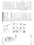
3.4
Rear Connector Panel
The following devices are located in the rear:
1. Power inlet (1).
2. Fuse holder (2).
3. Power switch (3).
4. SUB-D9 connector (female) for on-line/printer connection (4).
23(5$7,21
4.1
Switching-On the Unit
Switch the unit on using the power switch (see 2.3). For about 1 min. the
display will flash “TEST” in both rows while the electronic and mechanical
components are checked.
The instrument does not hold backup memory. When the instrument is turned
off, the results of the last analysis will be lost. The instrument is now ready to
start an analysis cycle. If the instrument detects a tube during this phase in
one of the sample positions, the t(;75$&7u message will be displayed. 7KHQ
WKHXVHUKDVWRUHPRYHWKDWWXEHILUVW.
17/29
+XPDQ
+XPD6HG
User Manual
4.2
General
Fill the tubes exactly up to the OHYHO mark on the tube.
The required volume is approx. 2 ml. The tolerance of the equipment with
regard to the level is PP DQG ~PP. Otherwise, the instrument will
display an t/(u level error message.
6KDNH WKH VDPSOH E\ VORZO\ LQYHUWLQJ WKH WXEH IRU DSSUR[LPDWHO\ PLQXWHV
EHIRUHLQVHUWLQJLWLQWRWKHLQVWUXPHQW
The test starts when the tube is inserted in the instrument. 'RQRWUHPRYHWKH
WXEH IURP LWV SRVLWLRQ XQWLO WKH WHVW LV FRPSOHWHG. Otherwise the test will be
aborted and the t6(u error message will appear on the results printout.
PLQXWHV after starting the test, the HQG RI WKH WHVW is reported displaying
the + UHVXOWV in the first line and the + UHVXOWV in the second line in the
corresponding position of the display. These results stay on the display until
another tube is inserted into that position
18/29
4.3
Status Displays
On the main screen, the following message is displayed:
The status of the working shelf is displayed. The GRW tu indicates that this
position is empty (no tube detected); a EODFN VTXDUH “ “ or “581” in the
second line indicates that WKLVSRVLWLRQLVLQXVH (the height of the black square
decrementing by minute to show the remaining time for the respective
analysis); a number means a result (1H in first line, 2H in second line) and
indicates that the WHVW KDV ILQLVKHG in this position; “(” indicates an HUURU
PHVVDJH(see Section 4 – error messages).
Example:
In this case, position 1 has ended, position 2 presents an error, positions 3 and
4 are in use (3 almost ending and 4 just at the beginning of the analysis time),
and 5 is empty.
This display is updated approx. every minute and whenever the user returns
from the menu. That is, approximately every minute newly detected and
finally analysed tubes appear on the display.
19/29
+XPDQ
+XPD6HG
User Manual
4.4
How Work
Switch on the unit (see section 3.1) and wait until the end of test cycle. When a
dot tu appears in a certain position load this position with a new tube (first
shake the tube as described in section 3.2). The t/2$'u message appears
when the instruments does not detect samples in any position.
When this sample is recognised by the instrument with the EODFN VTXDUH “ ”
in the first line , and t581u in the second line, the sample starts the analysis
cycle.
With every reading cycle the
remaining analysis.
EODFN VTXDUH
“
” gets smaller to indicate the
20/29
At the end of analysis the instruments displays two numbers. These numbers
mean a result, ( 67 ) +LQILUVWOLQH, ( 128 )+LQVHFRQGOLQH. At the same time
the instrument sends the results to a printer or computer via the serial port.
The sample can now be removed. When a GRWtu appears, this position can be
reloaded with a new tube.
1RWH: It is very important to wait until a dot “.” is displayed for a certain
position, indicating that the instrument recognised this position empty and
another sample will be accepted.
: Do not forget to mix the samples properly.
1RWH
The analysis results stay in their display position until a new sample is loaded
or the instrument is switched off.
Data can be transmitted to the computer system of the laboratory. So it is
necessary to know the communication protocol (Section 5 of this Manual).
Data can also be transmitted to any computer with a free serial port, only
adjusting the port parameters (section 5) on the +\SHU7HUPLQDO program and
printing from this program.
21/29
+XPDQ
+XPD6HG
User Manual
(55250(66$*(6
5.1
Errors
t/(u/HYHO(UURU
It indicates that the blood level is not correct.
Fill to the correct level and repeat the test.
If this error message is displayed for a position with no sample tube, call
technical service.
t6(u6DPSOH(UURU
It indicates that a sample has been removed before completing the test.
Repeat the test.
If this error message is displayed for a position with no sample tube, call
technical service.
5.2
Analytical Errors
/RZUHVXOWV
a. Possible blood clot in the sample. Repeat the test with a new sample.
b. When more than 2 hours have elapsed from the sample collection until the
test.
c. Insufficient sample amount, altering the blood / anticoagulant ratio,
affecting the test result.
+LJKUHVXOWV
a. Sample not shaken correctly.
b. If the Instrument has been installed on a surface that is not perfectly level. A
3% inclination can increase the ESR by 30%.
c. Excessive sample amount, altering the blood / anticoagulant ratio, affecting
the test result
22/29
21/,1(&20081,&$7,21635272&2/
6.1
General
The data is automatically sent at the end of the analysis.
6.2
Features
Are the same in the case of 7+(50,&35,17(5 or in the case of &20387(5.
One-way connection with a remote system.
DATA OUTPUT VIA RS232 9CTS FEMALE CONNECTOR
1RWH: For a correct functioning of the linkage and the Equipment it is very
important that only these 2 pins are connected to the shortest coupling wire.
,167580(173,16
TX : PIN 3 (transmission)
GND : PIN 5 (ground)
3523(57,(6
BAUD RATE : 9600
DATA BITS : 8
PARITY : NONE
STOP BIT : 1
WITHOUT FLUX CONTROL.
6.3
Data Package Contents
The data transmitted are characters with some control codes.
+($'(5VZLWFKRQLQVWUXPHQW
12h, 3Eh, 00h,1Bh, 77h, 01h
Five lines of text followed by 0Dh.
And at the end 1Bh, 40h 1Bh, 4Ah, 9Fh.
$77+((1'2)$1$/<6,6
The instrument sends a package. This package contains 3 parts, one part with
control codes at the beginning, one part with control codes at the end, and a
part with one record for every sample sent by the instrument.
23/29
+XPDQ
+XPD6HG
User Manual
7KHLQLWLDOFRQWUROFRGHDUH
12h, 3Eh, 00h,1Bh, 77h, 01h
Then the full record of every selected sample is transmitted.
(YHU\ VDPSOH UHFRUG LV FRPSRVHG of 18 BYTES followed by 0Dh. It is a text
record and its format is as follows:
tBB326B3BBBBBuIROORZHGE\'K
Where:
. “_” Equals a blank space = (20h).
. ”POS” are 3 characters. It’s a text “POS”.
. “P” is the position in the work shelf (1 to 5).
. “111” is the sample result of the first hour (1 to 159) In the case of error “111”
will be “E.S” or “E.L”
. “222” is the sample result of the second hour (1 to 159).
7KHODVWFRQWUROFRGHVDUH
1Bh, 40h, 1Bh, 4Ah, 9Fh.45 HUMASED 20/01-02/01
6.4
Thermal Printer
Connect the 7KHUPDO 3ULQWHU to the power supply. Connect de serial cable of
the 7KHUPDO 3ULQWHU to the online connector of +XPD6HG . Switch on the
printer. And now the printer is ready to work.
: Remember to switch off the printer when you finish work.
: The Thermal Printer works with thermal paper only. If the user loads
another kind of paper, possible DAMAGES are not covered by guaranty.
1RWH
1RWH
24/29
6(59,&(
7.1
General
The instrument has been designed to last several years with only a minimum
of maintenance, although some factors could influence the duration of this
period.
• The instrument has to be operated in a clean ambience and low dust
environment. Dust could be adhere to the reader and movable parts of the
machine. Cover the instrument when not in use.
• Clean the instrument with a humid cloth, when needed.
• Avoid spilling of liquids or reagents over the equipment
• Avoid breaking of tubes.
• The stability of the mains in the laboratory affects the life-time of the
electrical components of the equipment. Keep the instrument away from
other devices generating electromagnetic disturbances, such as centrifuges,
autoclaves, equipment not marked CE and, generally, equipment using
electronic power devices such as motors, pumps, electrovalves and
compressors.
7.2
Fuses Change
To replace the fuses, proceed as follows:
a. Disconnect the instrument from the power supply and pull out the
connector cable.
b. Remove the fuse-holder from its housing by opening the interior (red) part
of the fuse-holder with a suitable object (screwdriver).
c. Remove the fuse.
d. Substitute for 5x20 – 1 A. fuse.
e. Put the fuse-holder back to its original place..53 HumaSed 20/01-02/01
25/29
+XPDQ
+XPD6HG
User Manual
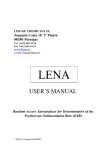
7.3
Electronic Parts
6FKHPDWLFV+80$6('
The instrument consists of the reader and the external power supply.
The performance data of the power supply are:
- Main voltage:
input 100V – 240V AC and output 5V CC
- Frequency:
47-63 Hz
- Current:
0.5 A
- Energy consumption: 10 VA
The power supply its connected to the instrument through a socket, followed
by a fuse and a switch. The main board is located behind the switch. The
socket, the fuse holder, the switch, and the serial socket can be found in the
rear of the instrument.
The main board is placed in the back cover. The main board controls all
functions of the instrument:
• The motor.
• The LCD display.
• The I.R. Board (reader and mechanic sensors)
• The serial port.
The temperature sensor is also located on the main board.
26/29
The I.R. board holds the 5 I.R readers (couple) which control the 5 reading
positions. It also contains the 2 I.R readers (couple) controlling the mechanics’
movements. They detect the high and the low position when light passes the
counter wheel aperture.
27/29
+XPDQ
+XPD6HG
User Manual
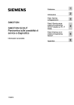
7.4
Mechanical Parts
28/29
The mechanical parts consist of the mechanical guide and the tube supports
(one each for the upper and the lower end of the tubes).
The mechanical guide supports the motor, the gear, the carriage, the bearings,
and the I. R. board. The mechanical guide is fixed with 2 screws, one in the
bottom and one at the top. To dismount the mechanical guide dismount the
LCD display first. Then take off the screws.
The I. R. board is fixed to the carriage by one screw. It is important to be fixed
correctly to avoid movement of the tubes. To dismount the I. R. board
dismount the mechanical guide.
Good alignment (through the specific hole in the mechanical guide) between
the emitters and the receptors of mechanical sensor couple is necessary to
have a clear pass of light.
The movement of the carriage is done by the motor, transmitted through the
gear at the carriage and it’s bearing. The motor has to put some pressure to
the carriage to hold it and it’s bearing (adjust approach motor by 2 screws).
Guide, carriage and bearing always have to be clean.
29/29
+XPDQ
+XPD6HG
User Manual
7.5
Test and Adjust the Instrument
•
, 5 6(16256 7(67
•
7(03(5$785( 6(1625
•
0(&+$1,&7(67
: With the instrument switched off (no tubes present),
place a jumper in JP1 (main board). Then switch the instrument on and wait
to the end of test. At the end of test the display shows the conditions of
every position in the first line. Now insert one tube to any position. For that
position a black square will appear (first line). If that tube is removed, the
black square has to be disappear. Otherwise a problem has occurred.
1RWH: The tube must be filled with blood or some other non transparent
medium.
: Following the procedure of I. R. Test (JP1) the
temperature can be monitored in the 2 last digits of the second line of the
display. To control that temperature the instrument has to be closed and
switched on for at least 1 hour. If any adjustment is necessary, open the
instrument adjust the trimmer, close the instrument and wait some
minutes to check it.
: When the instrument is in “LOAD”, put the jumper JP1. The
reader starts moving and will send the quantity of steps of every movement
ONLINE at the end of every movement (to printer and LCD) in hexadecimal
format. In first position the steps of the LOW-UP movement and in second
position the steps of UP-LOW movement are displayed. After some
movements check if the variation between movements is OK. A variation
greater than 10 steps is abnormal. Take off JP1 to stop the movements.
During this test analysis can be run. If the reproducibility of that test is bad,
the results might be erroneous. Check the conditions of the bearings. The
step motor could be dusty or not adjusted.
,I DIWHU VRPH PLQXWHV RI PRYLQJ XS RU GRZQ WKH LQVWUXPHQW GRHV QRW GHWHFW
WKH PHFKDQLFDO VHQVRU tu ZLOO EH GLVSOD\HG LQ WKHILUVW OLQHRI WKH VFUHHQ DQG
WKH PRYLQJ GLUHFWLRQ ZLOO EH FKDQJHG 7KLV PHDQV WKDW WKH LQVWUXPHQW KDV
VRPHPHFKDQLFDOSUREOHP
•
: The standard setting of the instrument will
not give results with temperature conversion. If temperature conversion is
needed, place a jumper in JP3. Then the results are converted depending on
the temperature (Manley table). This will be indicated by “*” prior to the
“LOAD”, and “TEST” display.
7(03(5$785( &219(56,21
30/29
7.6
How the Instrument Works
When the instrument is switched on, the LCD display will be set up. Then the
reader moves up and down to test the mechanic sensors. After arriving at the
down position the JP1 set is checked (to go a IR TEST), followed by a check for
the presence of any tube in the instrument. If a tube is detected the
“EXTRACT” message will be displayed. Take off the tube. If the tube is not
removed within two minutes the instrument will continue to “LOAD” status
(send the header online).
If a new tube is detected in “LOAD” an UP-DOWN movement will be carried
out and analysis will be started. First the reader controls if the filling levels. If
the level is incorrect, the system will printout “Level Error”. After 12 minutes
results will be printed out. With no other tube in work the reader will stop. If a
tube is removed during working time, the instrument will display “Sample
Error”.
The instrument detects new tubes only when it arrives at the low position. The
results remain in the LCD until another tube is loaded in that position. A dot is
displayed, when no tube could be detected in one position. If the instrument
does not detect any tube in any position it shows the “LOAD” message. If the
filling level of a tube is out of range of the reader’s movement, the instrument
might not detect a tube in this position.
31/29
+XPDQ
+XPD6HG
User Manual
+80$1
*HVHOOVFKDIWIÌU%LRFKHPLFDXQG'LDJQRVWLFDPE+
•
•
•)D[
H0DLOKXPDQ#KXPDQGH•ZZZKXPDQGH
0D[3ODQFN5LQJ :LHVEDGHQ *HUPDQ\
7HO
HumaSed 20
User Manual
5DQGRP$FFHVV$XWRDQDO\]HU
IRUWKH'HWHUPLQDWLRQRIWKH(U\WKURF\WH6HGLPHQWDWLRQ5DWH(65
V
&DW1R