1
Abrapol-2
Instruction Manual
Manual No.: 14227001
Date of Release: 18.02.1999
Abrapol-2
Instruction Manual
7DEOHRI&RQWHQWV
3DJH
User’s Guide .............................................................1
Reference Guide .....................................................15
Always state 6HULDO1R and 9ROWDJHIUHTXHQF\ if you have technical questions or when ordering spare parts.
You will find the Serial No. and Voltage on the type plate of the machine itself. We may also need the 'DWH
and $UWLFOH1R of the manual. This information is found on the front cover.
The following restrictions should be observed, as violation of the restrictions may cause cancellation of Struers
legal obligations:
,QVWUXFWLRQ0DQXDOV Struers Instruction Manual may only be used in connection with Struers equipment
covered by the Instruction Manual.
6HUYLFH0DQXDOV Struers Service Manual may only be used by a trained technician authorised by Struers.
The Service Manual may only be used in connection with Struers equipment covered by the Service Manual.
Struers assumes no responsibility for errors in the manual text/illustrations. The information in this manual is
subject to changes without notice. The manual may mention accessories or parts not included in the present
version of the equipment.
The contents of this manual is the property of Struers. Reproduction of any part of this manual without the
written permission of Struers is not allowed.
All rights reserved. © Struers 2002.
6WUXHUV$6
Valhøjs Allé 176
DK-2610 Rødovre/Copenhagen
Denmark
Telephone +45 36 70 35 00
Fax +45 38 27 27 01
Abrapol-2
Instruction Manual
Abrapol-2
Safety Precaution Sheet
To be read carefully
before use
The operator should be fully aware of the use of the machine according
to the instruction manual.
The machine must be placed in an adequate working position.
Be sure that the actual voltage corresponds to the voltage stated on the
side of the machine. The machine must be earthed.
Be sure that the water connections are without leaks. The main water
supply should be turned off if you leave the machine unattended.
Make sure that the specimens in the specimen holder are securely
fixed.
Keep clear of the preparation disc when operating.
If you observe malfunctions or hear unusual noises - stop the machine
and call technical service.
The equipment is designed for use with consumables supplied by Struers. If subjected to misuse, improper
installation, alteration, neglect, accident or improper repair, Struers will accept no responsibility for damage(s)
to the user or the equipment.
Dismantling of any part of the equipment, during service or repair, should always be performed by a qualified
technician (electromechanical, electronic, mechanical, pneumatic, etc.).
Abrapol-2
Instruction Manual
User’s Guide
7DEOHRI&RQWHQWV
3DJH
1. Installation
Checking the Contents of Packing.................................................. 3
Abrapol-2 .................................................................................. 3
Checking the Contents of Packing of Accessories .......................... 3
Recirculation Cooling Unit....................................................... 3
Dosing Unit (DOTWO)............................................................. 3
Solenoid Valve .......................................................................... 3
Drip Lubricator ........................................................................ 3
Microstop .................................................................................. 4
Placing Abrapol-2 ............................................................................ 4
Getting Acquainted with Abrapol-2................................................ 5
Front of Abrapol-2 .................................................................... 5
Supplying Power ............................................................................. 6
Direction of Rotation ................................................................ 6
Supplying Compressed Air ............................................................. 6
Mounting a Recirculation Cooling Unit (Accessory) ...................... 6
Mounting a Solenoid Valve (Accessory).......................................... 7
Mounting a Dosing Unit (Accessory) .............................................. 7
Mounting a Drip Lubricator (Accessory) ........................................ 7
Mounting Microstop (Accessory)..................................................... 7
2. Operation
Using the Controls .......................................................................... 8
Buttons/Adjusting Knobs ......................................................... 8
Front Panel Keys...................................................................... 9
Program Cards .............................................................................. 11
Programming a Preparation Step................................................. 11
When Grinding with Water ................................................... 11
When Grinding/polishing with Lubricant ............................. 11
Recommended Dosing Levels........................................................ 12
Editing a Preparation Step ........................................................... 12
Transferring a Preparation Method ............................................. 12
Editing a Preparation Method ...................................................... 12
Mounting a Preparation Disc........................................................ 12
Inserting the Specimen Holder..................................................... 13
Adjusting the Specimen Holder Position...................................... 13
Adjusting the Force ....................................................................... 13
Starting the Preparation Process ................................................. 13
When grinding with water..................................................... 13
When Grinding/polishing with Lubricant ............................. 13
1
Abrapol-2
Instruction Manual
Stopping the Preparation Process ................................................ 13
Setting Microstop .......................................................................... 14
Manual Functions ......................................................................... 14
When Grinding with Water ................................................... 14
When Grinding(polishing with Lubricant ............................. 14
2
Abrapol-2
Instruction Manual
1. Installation
&KHFNLQJWKH&RQWHQWVRI
3DFNLQJ
Abrapol-2
In the packing box you should find the following parts:
1
1
1
1
1
1
2
1
1
2
1
20
1
Abrapol-2 complete with inlet hose and cable
Splash ring
Lid
Non-return valve for recirculating Cooling Unit
Outlet hose
Fitting for outlet hose
Hose clamps for outlet hose
Hose for compressed air
Hose connection for compressed air
Hose clamps for compressed air
Hexagon key, 2.5 mm
Program Cards
Instruction Manual
1
1
1
20
Recirculation Cooling Unit
Drain angle
Funnel
Plastic bags
Dosing Unit (DOTWO)
1
1
4
1
4
1
2
3
Bottle holder plate
Nylon Strap
Screws M5x10
Screw M4x8
Washers M5
Washer M4
Lubricants
Suspensions
Solenoid Valve
1
1
2
2
Solenoid valve with mounting plate
Clamp for inlet hose
Washers
Screws (M5x10)
Drip Lubricator
1
1
2
2
Lubricant bottle
Mounting plate with valves and bottle holder
Screws (M5x10)
Washers (M5)
&KHFNLQJWKH&RQWHQWVRI
3DFNLQJRI$FFHVVRULHV
Recirculation Cooling Unit
3
Abrapol-2
Instruction Manual
Microstop
1
2
3
3
1
1
1
1
1
1
3ODFLQJ$EUDSRO
Abrapol-2 should be placed on a plane and horizontal floor. The
machine must be placed close to the power supply, water mains
and water outlet facilities.
4
Microswitch with mounting box
Screw (M5x10)
Screws (M5x16)
Washers (M5)
Cable clamp
Washer (M4)
Screw (M4x8)
Hexagon key (4 mm)
Micrometer screw
Instruction Manual
Abrapol-2
Instruction Manual
*HWWLQJ$FTXDLQWHGZLWK
$EUDSRO
Front of Abrapol-2
Take a moment to familiarise yourself with the location and
names of the Abrapol-2 components.
➅ ➆
➇ ➈
➂
➃
➄
➁
➀
c
d
Base unit
Specimen holder
Specimen holder motor
Quick-clamping device
Quick coupling flange
Handle for adjusting
specimen holder position
Nozzle block
j Cooling water
k
Front panel
Main Switch (left-hand side of cabinet)
Standby
Double start buttons
Emergency stop
Force selector
Display
5
Abrapol-2
Instruction Manual
6XSSO\LQJ3RZHU
,03257$17
Check that the mains voltage corresponds to the voltage stated on the type
plate on the side of the machine.
Mount a plug on the electric cable and connect it as follows:
Yellow/green: earth
Black/brown: phase
Direction of Rotation
Check that the preparation disc rotates counter-clockwise. If not
change the two phases.
6XSSO\LQJ&RPSUHVVHG$LU
Connect the compressed air supply with the inlet on the rear
side of the machine by means of the air hose and the hose
connection delivered with the machine.
Fasten the air hose with a hose clamp.
The pressure supply should be 6 bar and should be supplied
either from a central compressor, portable compressor with
compressed air reservoir or compressed-air bottle. A capacity of
20 l/min at atmospheric pressure is sufficient.
0RXQWLQJD5HFLUFXODWLRQ
&RROLQJ8QLW$FFHVVRU\
6
Place the recirculation cooling unit on either side of the
machine where you find it the most convenient.
Mount the non-return valve on the pump of the recirculation
cooling unit.
Mount the inlet hose from the machine on the non-return
valve.
Connect the electric cable from the pump to the machine.
Mount the outlet hose on the underside of the tank.
Mount the drain angle on the other end of the outlet hose by
means of the hose fitting and lead it down into the hole of the
recirculation cooling unit.
Check that there is a steady fall on the whole course of the
outlet hose.
Place a plastic bag in the tank and fill with water and
additive.
Abrapol-2
Instruction Manual
0RXQWLQJD6ROHQRLG9DOYH
$FFHVVRU\
If no recirculation cooling unit is mounted on Abrapol-2 a
solenoid valve must be mounted instead:
Fasten the solenoid valve on the rear side of the machine by
means of two screws with washers.
Connect the electric cable to the machine.
Cut the inlet hose at a distance of 100 mm from the machine
and connect the part still fixed on the machine to the inlet of
the valve and connect one end of the cut off part to the outlet
of the valve and the other end to the water tap.
0RXQWLQJD'RVLQJ8QLW
$FFHVVRU\
Mount the dosing box on the left side of Abrapol-2 by means
of screws.
Loosen the nozzle plate and screw the nozzle holder firmly on
the front plate of the machine. Fasten the nozzle plate again.
Connect the compressed air hose on the rear side of the
machine.
Connect the plug on the rear side of the machine and fasten
the cable with the nylon strap, screw and washer.
Place the bottle support under the bottle box.
Place the bottles, fill them, and connect them with the tubing.
Lubricant 1:
Lubricant 2:
Suspension 1:
Suspension 2:
Suspension 3:
blue lubricant
red lubricant
DP-Suspension, highest grain size
DP-Suspension, medium grain size
DP-Suspension, lowest grain size
,03257$17
Only use Struers suspension in the dosing unit.
0RXQWLQJD'ULS/XEULFDWRU
$FFHVVRU\
Fasten the mounting plate on the arm for the specimen
holder motor by means of the two screws with washers.
Connect the plug to the machine.
Fill the bottle with lubricant and place it in the lubricator.
0RXQWLQJ0LFURVWRS
$FFHVVRU\
Fasten the microswitch to the left side of the machine by
means of screws.
Connect the plug to the rear side of the machine and fasten
the cable with the cable clamp, the screw and washer.
Clamp the micrometer screw in the holder and mount the
holder to the arm for the specimen holder motor by means of
screws and washers.
7
Abrapol-2
Instruction Manual
2. Operation
8VLQJWKH&RQWUROV
Buttons/Adjusting Knobs
1DPH
.H\
See section Getting aquainted with Abrapol-2 for location of
buttons.
)XQFWLRQ
1DPH
.H\
)XQFWLRQ
%XWWRQV$GMXVWLQJ.QREV6HH'UDZLQJRI$EUDSRO
MAIN
SWITCH
STANDBY
DOUBLE
START
8
Turns on/off the main power of
the machine. The main switch is
located on the left-hand side of
the machine.
On/Off switch for daily use.
Starts the preparation process.
Press the double start button
simultaneously until the
specimen holder starts rotating.
EMER
GENCY
STOP
FORCE
SELECTOR
DISPLAY
Interrupts all functions. The
specimen holder remains in
lower position until the emergency button is released by
pulling the button.
For setting the required force.
The pre-set force can be read on
the manometer.
For reading the pre-set time of
grinding/polishing.
Abrapol-2
Instruction Manual
Front Panel Keys
9
Abrapol-2
Instruction Manual
1DPH
.H\
)XQFWLRQ
1DPH
.H\
)XQFWLRQ
3
Activates the dosing of lubricant.
Choose between bottle 1-2.
)
Activates the dosing of
suspension. Choose between
bottle 1-3.
1
Activates Microstop.
The present preparation
sequence is deleted when
AUTO is activated.
'DWD i
SPEED
j
TIME UP/
DOWN
k
WATER
'LVFUSP
Sets the speed of disc. Choose
between 150 rpm and 300 rpm.
;
;
Increases (;) or decreases
(;) the preparation time.
>
Activates the water flow.
Remember to adjust the flow on
the water tap.
l
LUBRICANT
SUSPENSION
MICROSTOP
&+2,&( STEP
KEYS
z
02'(
CREATE
z&UHDWH
8 keys for programming the
individual preparation steps.
With these keys a complete preparation method can be transfered to the machine memory.
To program a preparation step
CREATE mode should be
activated.
CLEAR
AUTO
z$XWR
When transferring a preparation
method or if you want to clear a
sequence AUTO mode should
be activated.
0$18$/)81&7,216/
DISC
STOP
WATER
10
,
The disc starts rotating
independently of the specimen
holder.
6
The machine is stopped at any
time during the preparation
process. By restart the machine
will start from the point where
the preparation was interrupted.
>
Activates the water supply.
Remember to adjust the flow on
the water tap.
LUBRICANT
21
SUSPENSION
3
Activates the dosing of the
selected lubricant.
)
Activates the dosing of the
selected suspension.
Abrapol-2
Instruction Manual
3URJUDP&DUGV
The program cards supplied with the machine are used for filling
in data about the preparation method of a given material. Data
about the single preparation step should be stated on the back of
the card and data about the material to be prepared as well as
information about the preparation disc and force should be stated
on the front of the card. The card should be placed on the front
panel so that it covers the Choice functions.
3URJUDPPLQJD3UHSDUDWLRQ
6WHS
8 different preparation steps can be programmed individually in
regard of time, speed of disc, water, type and dosing of lubricant
and suspension. These 8 steps can be combined in a number of
different ways so that different materials can be prepared
without having to repeat the programming.
Set the machine to CREATE mode.
Press the PREPARATION STEP KEY, 1 to 8.
Set the time by pressing the key TIME UP ; or TIME
DOWN ;. The pre-set time can be read on the display.
Set the speed of disc to either 150 rpm or 300 rpm by pressing
the key SPEED respectively on the left side of the key to
select 150 rpm and on the right side to select 300 rpm.
NB! The speed of disc will automatically be pre-set to 150 rpm
when an unprogrammed preparation step key is pressed.
When Grinding with Water
Select water supply by pressing the key WATER >.
When Grinding/Polishing with
Lubricant
Select the type of lubricant needed for the step by pressing
one of the two LUBRICANT keys Lub.1 3 or Lub.2 3.
When one of the lubricant keys has been activated the display
(left) shows level 0. Set the dosing level (0-10) by pressing the
selected lubricant key again. Each time you press, the dosing
level increases (see table below for Recommended Dosing
Levels).
Select the suspension needed for the step by pressing one of
the three SUSPENSION keys Susp.1 ) , Susp.2 ), or
Susp.3 ).
When one of the suspension keys has been activated the
display (right) shows level 0. Set the dosing level (0-10) by
pressing the selected suspension key. Each time you press,
the dosing level increases (see table below for Recommended
Dosing Levels).
11
Abrapol-2
Instruction Manual
5HFRPPHQGHG'RVLQJ/HYHOV
The table gives examples of recommended dosing levels for 7
different polishing cloths with different resilience. Remember
that these examples are Struers recommendations and therefore
adjustments may be needed according to the requirements of the
specimens to be prepared.
1DPHRI&ORWK
5HFRPPHQGHG'RVLQJ/HYHOV
/XEULFDQW
6XVSHQVLRQV
DP-Plan
3
5
DP-Pan
3
5
DP-Dur
6
5
DP-Dac
6
5
DP-Plus
8
5
DP-Mol
8
5
DP-Nap
8
5
(GLWLQJD3UHSDUDWLRQ6WHS
Set the machine to CREATE mode.
Press the key for the preparation step which should be edited.
Enter the required changes by means of the Data Keys.
7UDQVIHUULQJD3UHSDUDWLRQ
0HWKRG
Place the program card for the material to be prepared on the
two pins on the front plate so that is covers the Choice
Program. The keys can be activated through the card and a
light diode shows when a key is selected.
Press AUTO mode.
Press CLEAR to cancel existing step sequence.
Select a preparation method by pressing the relevant
PREPARATION STEP KEYS in the correct sequence. The
light diode for the first selected step turns green and the
following steps turn red indicating that the step to be
activated when the machine is started is the step with the
green light. The programmed data for this step can now be
read on the data keys.
(GLWLQJD3UHSDUDWLRQ0HWKRG
Set the machine to AUTO mode.
Press CLEAR to delete any existing sequence.
Select a new sequence with the PREPARATION STEP KEYS.
0RXQWLQJD3UHSDUDWLRQ'LVF
Place the disc on the turntable and move it until the three
pins engage with the holes in the turntable.
12
Abrapol-2
Instruction Manual
,QVHUWLQJWKH6SHFLPHQ+ROGHU
Place the specimen holder under the quick coupling.
Press and hold the black flange of the column down with your
thumbs while guiding the pressure tap of the specimen holder
into the coupling.
Release the black flange.
Turn the specimen holder until the three pins engage with
the corresponding holes.
$GMXVWLQJWKH6SHFLPHQ+ROGHU The position of the specimen holder has to be adjusted correctly
3RVLWLRQ
in relation to the preparation disc to get the best possible
preparation results.
Loosen the two handles placed on each side of the specimen
holder motor.
The specimen holder motor can now be moved manually to
the sides. The eccentricity can be read on the scale placed on
the specimen holder motor.
When the correct position is found fasten the handles again.
$GMXVWLQJWKH)RUFH
Turn the adjusting knob . to set the required force.
6WDUWLQJWKH3UHSDUDWLRQ
3URFHVV
Start the preparation step by pressing the two start buttons
simultaneously until specimen holder starts rotating.
When grinding with Water
Regulate the water flow on the tap.
When Grinding/Polishing with
Lubricant
Adjust the dosing valve of the drip lubricator.
The remaining time of preparation can be read on the display.
6WRSSLQJWKH3UHSDUDWLRQ
3URFHVV
When the time has elapsed the preparation disc will automatically stop and the specimen holder will return to its initial
position. The light diode for the next preparation step in the sequence turns green. The machine is now ready for the next step.
A preparation step can be stopped at any time during the
process by pressing the key STOP 6 in Manual Functions.
13
Abrapol-2
Instruction Manual
6HWWLQJ0LFURVWRS
Press the key MICROSTOP 1 in the Data field.
Press both start buttons. The specimen holder is activated
independently of the disc and moves downwards without
being rotated.
Turn the micrometer screw clockwise until STOP is read on
the display.
Press the key STOP 6. The specimen holder moves upwards
to its initial position.
Turn the micrometer screw counter-clockwise corresponding
to the required removal.
,03257$17
When Microstop is activated the machine does not automatically proceed to the
next step. Press the key STOP 6 and the next step will switch from red to green.
0DQXDO)XQFWLRQV
Manual operations are possible as the disc can run independently
of the specimen holder. The manual functions are found on the
lower right corner of the front panel indicated with /.
Start the disc separately by pressing the key DISC , .The
disc will operate according to the pre-set speed 150 rpm or
300 rpm as indicated with a light diode.
When Grinding with Water
Start the flow of water independently of a preparation step by
pressing the key WATER > in Manual Functions. If
lubricant and suspension are selected in the Data Program
water cannot be selected.
When Grinding/Polishing with
Lubricant
To be able to give manual dosing of lubricant and suspension
you should first choose the type of lubricant and suspension
you want to use in the data field and also set the dosing level.
You can now press the key LUBRICANT 3 and the key
SUSPENSION ) in Manual Functions. The dosing will be at
maximum for as long as the key is pressed.
Stop the disc and water by pressing the key STOP 6 or by
pressing the key DISC , and the key WATER >.
14
Abrapol-2
Instruction Manual
Reference Guide
7DEOHRI&RQWHQWV
3DJH
1. Accessories and Consumables
2. Struers Metalog Guide™
................................ 16
............................................. 17
3. Maintenance
Daily .............................................................................................. 18
Suspension nozzles................................................................. 18
Cleaning of nozzles alone ....................................................... 18
Weekly ........................................................................................... 18
Coolant.................................................................................... 18
Extended Cleaning of Nozzles and Tubes ............................. 18
Yearly ............................................................................................ 19
V-belts..................................................................................... 19
General Cleaning .......................................................................... 19
Cooling Tank .......................................................................... 19
Painted Surfaces .................................................................... 19
Air Filter................................................................................. 19
Lubricant Nozzles .................................................................. 19
Manual Lubrication ............................................................... 19
Lubrication Chart.......................................................................... 20
4. Machine Adjustments
Adjustment of counter-pressure ................................................... 21
Adjustment of down-speed............................................................ 21
Adjustment of brake action in bottom position of vertical
movement ...................................................................................... 21
Adjustment of quick-coupling ....................................................... 21
5. Trouble shooting
6. Technical Data
............................................................... 22
................................................................. 24
15
Abrapol-2
Instruction Manual
1. Accessories and Consumables
6SHFLILFDWLRQ
&RGH
&RROLQJXQLW
TRECI
Recirculating cooling unit, complete, 3-phased
$GGLWLYH
ADDUN
Bottle with 1 litre additive for cooling fluid
'RVLQJXQLW
DOTWO
Dosing unit for 2 lubricants and 3 suspensions,
complete
:DWHUYDOYH
Magnet valve for control of tap water supply, complete ABVEN
&RQQHFWLRQ.LWIRU0XOWLGRVHU
MULAT
Serial no. > 260 1383
'ULSOXEULFDWRU
Holder for one lubricant bottle, with valve for ON/OFF ABPYR
and mechanical regulation of quantity
0LFURVWRS
For stopping the process after removal of the required ABKRO
material
*ULQGLQJSROLVKLQJGLVF
Wet grinding disc, aluminium, for ø305 mm SiC-paper ROTAL
'3SROLVKLQJGLVFDOXPLQLXP
DETOT
ø230 mm (9")
DEDIF
ø250 mm (10")
DEDAL
ø300 mm (12")
0'SROLVKLQJGLVFDOXPLQLXP
DEMLA
ø200 mm (8")
DEMIF
ø250 mm (10")
DEMAL
ø300 mm (12")
3HWURGLVF0
PETIL
ø290 mm (8") for 200 mm specimen holder
PETHA
ø230 mm (9") for 160 mm specimen holder
6SHFLPHQKROGHUV
For many sizes and shapes of specimens. Ask for separate list.
7DEOHXQLWIRU$EUDSODQRU$EUDSRO
LABAB
With cabinet and trolley for recirculating cooling unit
and 1 set of tubes for cooling unit
6WRUDJHXQLW
LABCO
For accessories and consumables. The unit consists
of 2 chapters, one with 8 drawers, including a drawer
with inserts for specimen holders, and another one
with 8 shelves.
,QVHUWIRUVSHFLPHQKROGHUV
LABOA
Fits into the specimen holder drawer of the LABCO
storage unit
5HPHPEHU
Struers offers a comprehensive range of consumables for
grinding and polishing. Please ask for separate leaflets.
16
Abrapol-2
Instruction Manual
2. Struers Metalog Guide™
In Struers Metalog Guide™ you will find a detailed description of
grinding/polishing methods for automated mechanical specimen
preparation.
Struers Metalog Guide™ offers preparation methods for the most
common materials, based on a simple analysis of two key
properties: hardness and ductility. Finding the right method is
easy, including choice of consumables. Always consult Struers
Metalog Guide™ for the correct preparation method for the
actual specimens.
Struers Metalog Guide™ contains 6 useful chapters:
Metalogram: a quick and safe guide to the right preparation
method.
Metalog Methods: a complete catalogue of preparation methods,
based on Struers' vast store of materialographic experience, and
employing Struers' range of consumables.
Preparation Philosophy: the basics of modern specimen
preparation, seen from a professional point of view.
Metalog Process: the materialographic preparation process from
start to finish, logically explained.
Metalog Master: a combined trouble-shooting guide and supply of
in-depth information on the processes of mechanical preparation,
including an expert system for the solving of preparation
problems.
Consumables Specification: quick access to the relevant consumables for the chosen preparation methods.
A complete guide to materialographic specimen preparation.
Contact your local dealer for a free copy of Metalog Guide™.
17
Abrapol-2
Instruction Manual
3. Maintenance
'DLO\
Suspension nozzles
Cleaning of nozzles alone
:HHNO\
Coolant
Extended Cleaning of
Nozzles and Tubes
18
Shake the DP-suspensions lightly every morning. Blow the
nozzles free from suspension every night.
Should be carried out whenever the machine is not operated for
more than 4-6 hours:
Take a bottle of lukewarm water.
Replace the 1µm suspension bottle with the water bottle. If
1µm suspension is not used, choose the finest diamond
suspension used. This should correspond to SUSP. 3.
1. Press Create in MODE.
2. Remove the plastic suspension supply tube from suspension
nozzle 3.
3. Manually activate ABRASIVE for 5 seconds with a beaker
under the nozzle.
4. Refill tube.
5. Repeat procedure for SUSP. 2 and SUSP. 1.
Check if the supply of coolant in the tank is sufficient and not too
contaminated.
Must be performed every week or before breaks longer than 24
hours. The cleaning should be carried out in the following order:
1. Take a bottle of lukewarm water.
2. Replace the 1µm suspension bottle with the water bottle. If
1µm suspension is not used, choose the finest diamond
suspension used. This should correspond to SUSP. 3.
3. Press Create in the MODE.
4. Press key for step no. 1 in CHOICE.
5. Press SUSP. 3 in DATA.
6. Press SUSP. in Manual Control and hold a beaker under the
nozzle to avoid water splashing on the cloth. Press for 5-10
seconds.
7. Move the bottle with water from 1µm suspension to 3µm
suspension. Press SUSP. 2 corresponding to 3µm suspension.
Repeat point 6.
8. Repeat point 7 for 6µm, suspension, SUSP. 1.
Abrapol-2
Instruction Manual
<HDUO\
V-belts
Check regularly and at least once a year that the V-belts are
tight. Adjust if necessary.
*HQHUDO&OHDQLQJ
The machine and the recirculating cooling system should be kept
as clean as possible in order to avoid contamination of the
specimens.
Cooling Tank
Every time water is changed, the cooling tank should be cleaned
carefully to remove all grinding waste. Cleaning will be easier if
Struers plastic inserts are used. Remember to add Additive for
Cooling Fluid.
,03257$17
Do not use benzine or petroleum for cleaning when the additive is used.
Painted Surfaces
Painted surfaces and keyboard should be cleaned with a moist
cloth and common household detergents.
,03257$17
Never use alcohol, acetone or similar solvents.
Air Filter
The air filter should be cleaned regularly and water in the glass
vessel around the filter let out. This is carried out by pressing the
button at the bottom of the vessel. Access through hole in the rear
plate (fig. 10.3).
Lubricant Nozzles
The lubricant nozzles can be blocked by impurities in the
lubricant:
Remove the nozzle and try to blow it clean with compressed
air (blow from the point and inward).
If this does not help, the nozzle has to be cleaned with a very
fine needle under microscope.
Manual Lubrication
Before the nozzle is remounted, the whole system should be
washed out by activating the Manual lubricant key.
19
Abrapol-2
Instruction Manual
/XEULFDWLRQ&KDUW
3RLQWRI/XEULFDWLRQ
/XEULFDQW
,QWHUYDO
Quick coupling
Oil
200 h
Surfaces of columns
of up-and-down unit
Oil
200 h
Grinding disc bearing
Grease
2,000 h
Gear of gear motor
Grease
10,000 h or
2 years
Grease: eg. Shell Albida Grease LX
20
Abrapol-2
Instruction Manual
4. Machine Adjustments
The Adjustments listed below are only required after repairs or
service.
$GMXVWPHQWRI&RXQWHUSUHVVXUH Counter-pressure is the pressure on the primary side of the
compressed air cylinder, which counterbalances the weight of the
up/down unit. The counter-pressure returns the unit to its initial
top position. It is adjusted by a reduction valve (fig. 20b.8). The
correct pressure is 2.7 bar (when using air to eliminate
hysteresis). Measure with a precision manometer.
$GMXVWPHQWRI'RZQVSHHG
The Down-speed is adjusted by an adjustable throttle valve (fig.
10.4), normal position of the valve being approx. 1 3/4 turn from
home position. To obtain faster travel, turn the valve approx.
1/4 turn. Screwing the valve beyond the latter position may cause
problems in the form of excessive initial grinding pressure (for
approx. 1/4-1 sec), involving a risk of the specimen tearing the
grinding paper or polishing cloth. When specimens are protruding
more than 6 mm from the sample holder disc, the brake (see
below) does not work, and in this case the throttle valve (fig. 10.4)
is closed 1/2 to 1 turn to reduce the down-speed.
$GMXVWPHQWRIEUDNHDFWLRQLQ
ERWWRPSRVLWLRQRIYHUWLFDO
PRYHPHQW
The brake incorporated in the compressed air cylinder comes into
operation 5-10 mm above the polishing disc, depending on how
far specimens protrude from the specimen holder. Access to the
adjusting screw is gained through two holes at the left side plate.
The upper screw adjusts the braking action of the up/down unit
when it returns to its initial top position. Normal adjustment of
the down-speed brake action is approx. 1/8 turn from the home
position. Adjustment is very delicate, because the braking action
should not prevent the specimen holder from contact with the
grinding disc when working at a low process pressure. This may
cause problems, particularly with thin specimens, therefore
specimens should always protrude approx. 2.5 mm from the
specimen holder.
$GMXVWPHQWRITXLFNFRXSOLQJ
After loosening the two screws (fig. 19.10) the position of the
quick-coupling on the shaft can be vertically adjusted. Mounting
the quick-coupling too close to the shaft end may transmit the
grinding pressure to the specimen holder through the two lockballs. This would damage the specimen holder stud and make
removal of the specimen holder difficult. Incorrect mounting can
be noticed either by measuring or by the fact that the lock slots of
the specimen holder studs have become smooth from wear.
21
Abrapol-2
Instruction Manual
5. Trouble shooting
(UURU
Display shows "ES"
&DXVH
The emergency stop button has
been activated (Emergency Stop)
One of the motors has been
overloaded.
No suspension escapes the nozzles
The nozzles are blocked.
The suspensions do not have the
right viscosity
$FWLRQ
Release the emergency stop button
by pulling the button.
Wait till "ES" disappears from the
display. Reduce the grinding and
polishing pressure.
If "ES" immediately appears again, a
phase is missing or the motor is
defective.
Clean the nozzles.
You are using suspensions not
manufactured by Struers:
Change to the original Struers
suspensions.
The suspensions are too old:
Change the suspensions.
Centre of specimen not polished
(after previous grinding on PetrodiscM or diamond grinding disc)
The polishing suddenly takes more
time
The supply of coolant is inadequate
22
The specimens go too far beyond
the outer edge of the grinding disc.
The polishing cloth is filled up with
removed material.
The suspension ability has
deteriorated and the diamonds sink
to the bottom.
The cooling pump rotates the wrong
way.
There is no water in the tank.
The suspension bottles have not
been shaken for a long time:
Shake the bottles.
Adjust the position of the specimen
holder disc in proportion to the
grinding disc.
Change polishing cloth.
Shake the suspension bottle.
Change two phases in the electric
connection of the pump.
Fill up with water and additive.
Abrapol-2
Instruction Manual
(UURU
The grinding paper is torn up by
contact with the specimens
&DXVH
Excessive grinding pressure.
The specimens are not at the same
level.
Soft and brittle specimens.
Specimen holder lowered too fast
(especially if the specimens project
more than 6 mm over the edge).
Incorrect adjustment of the shock
reduction device in the compressedair cylinder.
Display shows NO AIR
Missing or incomplete air supply.
Display defective
Defect in the circuit of the display or
defect in the CPU circuit.
$FWLRQ
Reduce the pressure with the
reduction valve (fig. 1.7).
Use Struers levelling apparatus.
Use adhesive grinding paper or run a
dummy specimen over the whole
surface of the grinding paper.
The speed of the downward
movement is controlled by a throttle
valve (fig. 20.8). Adjust the speed by
turning the screw at the top of the
valve, clockwise for decreasing and
counter-clockwise for increasing the
speed.
Adjust the screw on the cylinder.
Access through the lower hole in the
side plate (behind the bottles if doser
unit is mounted). Normal setting 1/8
rotation from the starting point.
Check that air hoses are tight and
properly clamped.
Replace the display.
23
Abrapol-2
Instruction Manual
$EUDSRO
Voltage/frequency
6. Technical Data
3 x 200V, 50/60Hz, max. 6.8A
3 x 220V, 50/60Hz, max. 2 A
3 x 380V, 50Hz, max. 3.8 A
3 x 415V, 50Hz, max. 3.6 A
3 x 440V, 60Hz, max. 3.5 A
3 x 480V, 60Hz, max. 3.6 A
Internal fuse
1.6 AT
Entry pressure
6 bar ±0.2
Maximum consumption: approx. 20 l/min.
Main motor
550W (0.75 hp) at disc rotation 150 rpm
1100W (1.5 hp) at disc rotation 300 rpm
Specimen holder motor
150 W (0.2 hp)
Rotational speed
Disc: 150 rpm or 300 rpm
Specimen holder: 150 rpm
Vertical working pressure
50-700 N
Timer intervals
From 0:05 to 99:55 min at 0:05 min intervals
Dimensions and Weight
Height: 1420 mm
Length: 850 mm
Depth: 510 mm
Weight: 250 kg
Noise Level
The noise level of the machine is 55 dB (A) measured at idle
running at a distance of 1 m/39.4” from the machine.
Safety standard
IEC 204 / EN 60204-1 (VDE 0113)
5HFLUFXODWLQJ&RROLQJ8QLW
Motor
110 W
Pump
64 l/min (1 m water column pressure at 0.1 atm)
Dimensions and Weight
Height: 410 mm
Length: 400 mm
Depth: 500 mm
Weight: about 7.2 kg
Standard
IP 44
24
Abrapol-2
Spare Parts and Diagrams
Manual No.: 14227001
Date of Release: 18.02.1999
Revised: 09.06.2000
Abrapol-2
Spare Parts and Diagrams
$OZD\VVWDWH6HULDO1RDQG9ROWDJHIUHTXHQF\
LI\RXKDYHWHFKQLFDOTXHVWLRQVRUZKHQRUGHULQJVSDUHSDUWV
The following restrictions should be observed, as violation of the restrictions may cause cancellation of Struers
legal obligations:
,QVWUXFWLRQ0DQXDOV Struers Instruction Manual may only be used in connection with Struers equipment
covered by the Instruction Manual.
6HUYLFH0DQXDOV Struers Service Manual may only be used by a trained technician authorised by Struers.
The Service Manual may only be used in connection with Struers equipment covered by the Service Manual.
Struers assumes no responsibility for errors in the manual text/illustrations. The information in this manual is
subject to changes without notice. The manual may mention accessories or parts not included in the present
version of the equipment.
The contents of this manual is the property of Struers. Reproduction of any part of this manual without the
written permission of Struers is not allowed.
All rights reserved. © Struers 2000.
6WUXHUV$6
Valhøjs Allé 176
DK-2610 Rødovre/Copenhagen
Denmark
Telephone +45 36 70 35 00
Telefax: +45 38 27 27 01
Abrapol-2
Spare Parts and Diagrams
1. Spare parts and Diagrams
3KRWRVDQGGUDZLQJV
'LDJUDPV
7DEOHRIFRQWHQWV
1 Front
2 Controls
3 Placing the program card
4 Inserting the specimen holder
5 Main switch
6 Non-return valve
7 Connection of recirculating pump
8 Valve for mains water
9 Dosing unit
10 Dosing unit, connection
11 Drip lubricator
12 Microstop
13 Contents of packing case
14 Recirculating Cooling Unit
15 Valve for mains water
16 Dosing unit
17 Drip lubricator
18 Microstop
19 Abrapol-2
20 Pneumatic parts
21 Pneumatic diagram
22 Contactor box
23 Circuit boards
24
25
26
27
28
29
30
31
32
'UDZLQJ
Circuit diagram for mains voltage........................ 14221007G
Wiring Diagram, Contactor Box ........................... 14221012H
Control Voltage Wiring Diagram.......................... 14221034D
Connecting Diagram Supply Voltage 100-230V....14221013A
Control Voltage Circuit Diagram.......................... 14221033D
Circuit Diagram, Keyboard/Display Board ............. 14221052
Circuit Diagram, In/out, Supply Board .................14221062B
Pneumatic Doser Diagram.....................................14220536A
Pneumatic Mounting Diagram ............................. 14220231K
Thermal relay settings...........................................14221045C
The drawings are not to scale. Some of the drawings may contain
position numbers not used in connection with this manual.
1
Abrapol-2
Spare Parts and Diagrams
)URQW
Fig. 1
3RVDQG'HVFULSWLRQ
6SDUH3DUW1R
Abrapol-2
Spare Parts and Diagrams
&RQWUROV
Fig. 2
3RVDQG'HVFULSWLRQ
6SDUH3DUW1R
Abrapol-2
Spare Parts and Diagrams
3ODFLQJWKH3URJUDP&DUG
Fig. 3
3RVDQG'HVFULSWLRQ
1
2
3
4
5
6SDUH3DUW1R
Switch........................................................................ 394MP040
Front plate with touch pad keyboard......................... 14220087
Program set V02, 2 pcs. ............................................ 422MP040
Pin for program card................................................. 422MP041
Ball cock .................................................................... 383MP020
Flex tube, complete ................................................... 422MP003
Abrapol-2
Spare Parts and Diagrams
,QVHUWLQJWKH6SHFLPHQ+ROGHU
Fig. 4
Abrapol-2
Spare Parts and Diagrams
0DLQ6ZLWFK
Fig. 5
Abrapol-2
Spare Parts and Diagrams
1RQUHWXUQYDOYH
Fig. 6
3RVDQG'HVFULSWLRQ
1
6SDUH3DUW1R
Non-return valve, 3/4" for TRECI ............................ 260MP082
Abrapol-2
Spare Parts and Diagrams
&RQQHFWLRQRI
5HFLUFXODWLQJ3XPS
Abrapol-2
Spare Parts and Diagrams
9DOYHIRUPDLQVZDWHU
Fig. 8
Abrapol-2
Spare Parts and Diagrams
'RVLQJ8QLW
Fig. 9
Abrapol-2
Spare Parts and Diagrams
'RVLQJ8QLW&RQQHFWLRQ
Fig. 10
Abrapol-2
Spare Parts and Diagrams
'ULSOXEULFDWRU
Fig. 11
Abrapol-2
Spare Parts and Diagrams
0LFURVWRS
Fig. 12
Abrapol-2
Spare Parts and Diagrams
&RQWHQWVRI3DFNLQJ&DVH
Fig. 13
3RVDQG'HVFULSWLRQ
3
6SDUH3DUW1R
Water hose 1/2 " (10m)..............................................RNU29316
d DP-disc or MD- disc to be ordered separately
Abrapol-2
Spare Parts and Diagrams
5HFLUFXODWLQJ&RROLQJ8QLW
Fig. 14
Abrapol-2
Spare Parts and Diagrams
9DOYHIRU0DLQV:DWHU
Fig. 15
3RVDQG'HVFULSWLRQ
1
1
5a
5a
5b
5b
6
6SDUH3DUW1R
ABVEN Solenoid valve, complete 50Hz ..................... 04226902
ABVEN Solenoid valve, complete 60Hz ..................... 04226903
Solenoid 50Hz ........................................................... 375MP192
Solenoid 60Hz ........................................................... 375MP193
Solenoid valve for water, 50Hz............................... 422MP004A
Solenoid valve for water, 60Hz............................... 422MP004B
3-pole box, contact plug incl. .................................... 422MP005
Abrapol-2
Spare Parts and Diagrams
'RVLQJ8QLW
Fig. 16
3RVDQG'HVFULSWLRQ
1
2
3
4
5
6
13
14
15
16
6SDUH3DUW1R
Bottle, 1L, cap with hole........................................... 376MP084
Cap plate for lubricant bottle (1000 ml)................... 375MP028
9-pole box incl. contact plug ..................................... 422MP008
Water trap................................................................. 435MP017
Lubricant pump, complete........................................ 375MP025
Box without valves and pumps................................. 422MP006
Solenoid valve ........................................................... 375MP187
O-ring ø10.82-1.78 (10 pcs) ....................................... 130MP057
Air tube ø5/ø3.2 (2m), Blue ....................................... 375MP178
Suspension bottle, 250 ml......................................... 375MP027
Non-return valve for cap plate ................................. 422MP018
Cap plate for suspension bottle (250 ml).................. 422MP017
DP-Suspension nozzle, complete .............................. 375MP031
Lubricant nozzle, complete ....................................... 375MP032
Nozzle holder plate ................................................... 422MP013
Nozzle elbow.............................................................. 422MP014
Lubricant pump, complete........................................ 375MP025
Throttle gauge for air tubing, suspension nozzle..... 422MP016
Nozzle holder cover ................................................... 422MP009
Abrapol-2
Spare Parts and Diagrams
3RVDQG'HVFULSWLRQ
$% 'RVLQJ8QLW
Fig. 16 A/B
6SDUH3DUW1R
$
1
2
3
Lubricant nozzle head............................................... 375MP035
O-ring ø3 x 1 for lubricant nozzle head .................... 375MP036
Lubricant nozzle screw ............................................. 375MP038
$%
4
5
6
O-ring ø4,48 x 1,78 for nozzle screw......................... 375MP037
Guide ball for nozzle ................................................. 375MP270
O-ring ø16 x 2 for nozzle ball.................................... 422MP015
%
1
3
DP-Suspension nozzle head...................................... 375MP034
DP-Suspension nozzle screw .................................... 375MP039
Abrapol-2
Spare Parts and Diagrams
&
'RVLQJ8QLW
16C (16.4)
3RVDQG'HVFULSWLRQ
1
2
3
4
5
6
6SDUH3DUW1R
Lubricant pump, complete........................................ 375MP025
Diaphragm ................................................................ 375MP052
Piston ........................................................................ 375MP053
Spring ........................................................................ 375MP020
Nipple ........................................................................ 375MP022
Banjo connection ....................................................... 375MP023
Check valve (non-return valve) ................................ 375MP024
Solenoid valve ........................................................... 375MP187
Filter.......................................................................... 422MP007
Throttle gauge for air tubing, suspension nozzle..... 422MP016
Cap plate for suspension bottle ................................ 422MP017
Abrapol-2
Spare Parts and Diagrams
'ULS/XEULFDWRU
Fig. 17
3RVDQG'HVFULSWLRQ
1
2
3
4
5
8
9
6SDUH3DUW1R
Bottle, 2 l................................................................... 158MP016
Valve needle .............................................................. 158MP010
Valve outlet ............................................................... 158MP005
Solenoid valve ........................................................... 376MP044
Nozzle with fittings................................................... 422MP019
Lubricator cup........................................................... 158MP014
Bottle fixture............................................................. 158MP015
O-ring, ø11.91x2.62................................................... 249MP032
10 3-pole box incl. contact plug ..................................... 422MP005
11 Solenoid Housing ........................................................ 14229048
Abrapol-2
Spare Parts and Diagrams
0LFURVWRS
Fig. 18
3RVDQG'HVFULSWLRQ
6SDUH3DUW1R
4 3-pole box incl. contact plug ..................................... 422MP005
6 Microswitch............................................................... 260MP202
13 Micrometer screw...................................................... 260MP206
Abrapol-2
Spare Parts and Diagrams
$EUDSRO
Fig. 19
3RVDQG'HVFULSWLRQ
1
2
3
4
5
7
8
9
10
11
12
14
15
16
17
18
19
20
21
22
22
23
24
25
26
27
6SDUH3DUW1R
V-belt pulley (state frequency) ................................. 260MP068
Bushing for V-Belt pulley (260MP68) ...................... 260MP069
Nipple and connecting piece ..................................... 260MP168
Emergency stop switch element ............................... 381MP440
Drain tray.................................................................. 260MP185
Emergency stop push-button,
without switch element ............................................ 381MP439
Cap for 260MP004 .................................................... 260MP005
Push button, start..................................................... 260MP004
Splash guard ............................................................. 260MP143
Lid for 260MP143 ..................................................... 260MP144
Quick-release coupling, complete ............................. 260MP027
Damper coupling, complete ...................................... 260MP080
Damper coupling with lower flanger.......................... 12600330
Handle ....................................................................... 260MP155
Specimen holder motor
(state voltage and frequency) ................................... 260MP085
Sliding piece .............................................................. 422MP021
Dial rail ..................................................................... 422MP022
Pressure spring ......................................................... 422MP023
Microswitch............................................................... 260MP009
Double-acting compressed-air cylinder .................... 260MP102
V-belt pulley for main motor .................................... 260MP071
Bushing for 260MP071 ............................................. 260MP072
Driving belt, 50 Hz, 2 pcs. ........................................ 260MP073
Driving belt, 60 Hz, 2 pcs. ........................................ 260MP083
Main motor (state voltage and frequency) ............... 260MP070
Hose, complete .......................................................... 422MP003
Water Cock 1/4” ........................................................ 383MP020
Column for Abra arm.................................................. 12600312
Flexible water nozzle, complete.................................. 42MP003
Abrapol-2
Spare Parts and Diagrams
)LJ'UDZLQJ
Abrapol-2
Spare Parts and Diagrams
$$EUDSRO
Fig. 19A
3RVDQG'HVFULSWLRQ
1
2
3
4
5
6
7
8
9
10
11
12
14
15
16
6SDUH3DUW1R
Bearing unit complete, but without turntable,
V-belt pulley and bearing flange .............................. 260MP065
Turntable w. quad ring and
4xM8 screw holes (300mm) ........................................ 14590010
Axial bearing ø100/ø135 x 25.................................... 260MP017
Shell ALBIDA LX Grease ......................................... 381MP415
Bearing flange........................................................... 260MP197
Roller bearing, upper, 6007 ...................................... 260MP018
V-belt pulley (please state frequency) ...................... 260MP068
Roller bearing, lower, 6007RS .................................. 260MP018
Bush for V-belt pulley............................................... 260MP069
Seeger ring I 62 x 2 ................................................... 260MP019
Seeger ring U 35 x 1.5............................................... 260MP067
Bearing protection ring............................................. 260MP183
V-ring VA 130 ........................................................... 260MP184
Thrust collar, set of 4................................................ 315MP059
Quad-ring .................................................................... 2IQ04450
Quad-ring .................................................................... 2IQ04441
Quad-ring .................................................................... 2IQ04326
Abrapol-2
Spare Parts and Diagrams
3QHXPDWLF3DUWV
Fig. 20
3RVDQG'HVFULSWLRQ
1
2
3
4
6
6SDUH3DUW1R
Reducing valve .......................................................... 368MP330
Throttle sound absorber ........................................... 422MP024
Manometer .................................................................. 14229027
Solenoid valve ........................................................... 260MP012
Quick exhaust valve.................................................... 14222900
Filter/reduction valve unit - SMC ............................ 375MP199
Filter glass for 375MP199 ........................................ 381MP435
8 Reduction valve......................................................... 2YR00003
9 Non-return valve....................................................... 260MP127
10 Non-return throttle valve ......................................... 260MP128
Abrapol-2
Spare Parts and Diagrams
3QHXPDWLF'LDJUDP
Fig. 21 (Drawing 14220236)
3RVDQG'HVFULSWLRQ
6SDUH3DUW1R
Abrapol-2
Spare Parts and Diagrams
3RVDQG'HVFULSWLRQ
&RQWDFWRU%R[
Fig. 22
1
6SDUH3DUW1R
Thermo relay F1 (200-240V)..................................... 381MP234
Thermo relay F1 (380-480V)................................... 394MP050B
2 Thermo relay F2 (200-240V)................................... 394MP049C
Thermo relay F2 (380-480V)..................................... 381MP234
3 Mains noise filter ...................................................... 394MP045
4/5 Thermo relay F3/F4 (200-240V) ............................... 381MP233
Thermo relay F3/F4 (380-480V) ............................. 375MP263B
6 Transformer T1 (state voltage)................................. 394MP043
7 Main switch................................................................ 2SE00149
8 Fuse F12, 2.5 AT (10 pcs.) ........................................ RFU14000
9 Fuse F11, 1.6 AT (10 pcs.) ........................................ 422MP027
10 Auxiliary switch for K4............................................. 381MP237
11 Contactor (K1, K2, K3, K4) ...................................... 376MP110
Abrapol-2
Spare Parts and Diagrams
3RVDQG'HVFULSWLRQ
&LUFXLW%RDUGV
Fig. 23
1
2
3
4
5
6SDUH3DUW1R
Display Board ........................................................... 422MP010
CPU Board ................................................................ 422MP011
PROMP, latest version ............................................. 422MP040
Interface/Power Supply Board.................................. 422MP012
3-pole cabled plug for solenoid valve ........................ 422MP029
9-pole cabled plug for solenoid valve ........................ 422MP030
Fuse on PCB F5 (2.5 AT) .......................................... 422MP031
Fuse on PCB F6 (1.6 AT) .......................................... 422MP032
Noise liNer
Mains
switch.
Haupt-.
schalter.
Control
Voltage
Steuer spannung
Ki
Ti
F9
W3
4o1°
setting Table
Fi-F4. See
Sehe Fuse
Sicherungstabelle
C go
_______________
wh ~
I4AWGo4
6OHZt
xi
Connections for Struers
recirc. pump
3 x U/0i3 kW
bk
bo
block sckworz
brownobrOun
ye/go yellow/green
Anschluss für Struers
Rezirkulationspumpe
3 x 0.13 kW
Ml
All wirings 10
Sample mover motor.
Polishing disc motor.
Probenhalter Motor.
Polierscheibe Motor.
gelb/grUn
C’ ttoo~cf .tA’~’~
A
Fose
....
bo-v~nc. g,l,y~~
t1(. Cyretwf Wtto~a
y(
NJ ~ B3,~’j
J
u~e Abropol - 2
~.:
~
Et
1~~i
-yig~ty
si rd ~
qp/t-’
F~1aA -‘ F~2OA S.i~.’YkGttl/ f ’
75
±
Olod000hoflO
STRUERS A/s
COOL
Aflv.i typo
Circ~iitDiogront for Moino Vollogo.
Schaliplon für Metzsponnuog.
3 220-SOOV/
V 0fl-CONy,
EOO~
005
U2210076
A
I
SR
I
I
I
C
D
I
I
E
I
See connecting diagram
Sehe Verbindungs—schaltplan
F
Connections for Struers Rec. Pump.
Noise
Filter.
‘u’I
xl
Control voltage trafo
Steuerspannungstrafo
~r
100
~T1
—
230V
4
3
2
.~fl+D2AD244~2—
80480 UI8/JW
A~.~
,to~22w. n.Tl.rdl, o.X2 tDf.23/9-8881&l/JT Ct T..mO.o8 88dot.p.t~t.gnM p8 CAD.
ID/Il—DO
dIV
Ct P12 t lB—OS DAT 0/7—53 080/dIv
C, T,ofe 4.4 2 1/5—80 808
00 SpedMm —> 8M.d 24/5—81 ~W/#4
S Die. th.4*,9.e 18/5—00 00J/0BI
8, PB->~’2.P5—OPII 30/4—80 LR/54
W3
W4
Aol,.
Nd
5.kU0eo~n.t0d
MOttotho± I lkke
OS/ISO
ang.2768
tol.
1:1
toonOl
Wiring UIog.~m. Contactor
14221012H
A
I
C
I
D
I
efte,
0010
V fl,
IT~~0
11 O49~DRY
9
F
to.—
‘/t
-~
00
0t
0
(~0~
NJ
0
0
><
-~
N
‘-0
o
C’)
-~
~
C’)
N
NO)
a
N
I
li-i
C—
L() ~
Ji L
-.y N CC
0 -0
I’)
01
too
~
—0
~0-
a)
—
N N N
cn C’) CC
lU
U
-J
C
0)
o
to 01 N N
0
CC
45)
o
‘-toO
(0,~
>x
37
38
SI)
-)‘/~co
-
L C’~)
u-ti)
0~
0
0)
—
-A-
C
C’)
~
35
36
(0
0)
‘~
f4~1+I~E
~rci:Lr
L~
—
~2
g
03
o
-
N
(0
S
U
I,
—
N.
Ito
40
41
42
tO
C)
C)
C
o
c0n~-
U
U)
‘0t
Ce)
43
3:
0
~
-:
N
II)
to
N’;
0
0
(7
‘~~/
D
III
-J
SN
I-oH
TLF
{oy
97bh~
~
U~
~
~
.¼~.C)r,
2~l.~)
f,f1~7~/
STRUERS A/iS
_________
EXIO~
(N
NJ
0
<ode.
c
Any type.
Control Voltage Wiring Diagram
~4O yec~t
(81;
1~U~
~fi~
I
~
c~o~
-0
~
Mat,
N~C’)
(I)
_.~9
MSlestok: Qverfladebehandi.
(N
At
~io
NaVC)BJ/~41
Data
Erst.:
3 889
1422 1O3L~D
Primary Supply
Primary Supply
PrimAr Versorgung
llO/115V AC
PrimAr Versorgung
100V AC
115V
lb5V
I
0-
I
-0--
boy
boy
I
I
F=
0,
0v
°v
0, 63A
I
-C
I
--~
lb 5V
0
boy
bb5V
110/11 5V
II
boy
—
II
II
II
0—
-
11 5V
11 5V
I
-0--
I
bOy
boy
I
I
F=
0,33A
°v
°v
I
115V
0
II
Primary Supply
PrimAr Versorgung
215/220V AC
Primary Supply
Primär Versorgung
200V AC
F=
0,33A
II
boy
0
r~
0
—
200V
II
Jo—
2b5/220V
boy
L~
°v
°v
I
II
II
S
II
-
Primary Supply
PrimAr Versorgung
230V AC
lb 5V
-0
I
11 5V
I
boy
I
0v
8*
9
.5
boy
SCR
°v
F=
0,33A
°v
-0
0
6
0
*
bi 5V
230V
11
II
13
11 5V
9, 5V
ov
boy
boy
II
24V
II
0v
I
StrueN
I
‘119
Connecting Diagram Supp. Volt. lOO-230V
.-schaltpl. Versorg. sp. lOO-230V
-
14e-01-24-121$9
L4~22
1013A
Fl.
96
F3
96
odi
F2 96
rdlB
Wy
odli
Xl/.1
W6
rd4
s~
a
13
INTERFACE BOARD
tWO
__
Wy
rdl
Eli
10
*N24.
X143
~1.6A
9.sv
‘-
,____
X615
W5 rd3
-A
X613
,~
F12
rd2
,,
24VF
W5 rd2
rd~ 22
L
‘dl
X612
X21O
W rdl
X611
-~-u-~----~----*~-
rd
SAMPLE MOVER
MOTOR,
RECSR5(.PUMP
24V0
ws c-d14
X214
rdl4
X21
1
Y5~.j,~WATER
SOL.’<. <
~grVALVE
.8
‘
1
~
5(2
LI
/ Xl12
A2fl
‘ysU
~7a
X2~15 W5 Cd15
2
~rd16~ ulE
-
RL3
PORT
RL2
RLI
RLO
A
0
X11’tl X28
~
A
X68,
W5rd16
-
..
Ki
..—.
X14~7
LUB 1
A
LUB I
Y2. W1O1 rd 2
XlOl
-
X13~2
r
X13~4
UNIT
I--I
X6~2
VS
~
X132
SUSP 1
c— ~
X13t2
SUSP2
~ SUSP3
Y7
t0~
X132
-,~
____________
p
—
.
X137
,_~,
—
WIO
d ,g~~
20 2
1k
N
I
X135
<L~~
YB
r~’~ X13 6
r 35
~
6
N~4
INPUT A
~4
X14
WlO2rdl.7
X716
RLO
78)
9~
U)
W7-rdl
IX102Wl~d Xl~,3
3
SIGN. FOR
LUB UNIT
SIGN. FOR
DOSER UNIT
~ X.132
—
NC.
W7-rd3
X133
~
‘0~
rd2C
0
rd37
~E
U120
rd4O
~S4
Xi/.
~
MS. DOWN
m
C)
—
~C
(1)
—
U121
RL1
X712
U122
RL2
X7l1
U123
RL3
U124
RU.
Q~
U125
RL5
X71O
U118
RL2
U117
RL3
U116
U115
RL5
U114
-.1,1
9..
to)
H
W5 ye/fin
~ 27J727
Front
Contaclor
Box
W6rd5, _-&,~//6rd~~3 PB. START B
0
j.—53
>~52
EMERG. STOP
X14
,~.-ij~rd3O5~3O5STAND-BY
MS. STOP
W103rd2
‘I)
C).
53
P.8. START A
X1L.
1~
X7l~~ rd43
RL/.
X64
‘/0
rd42
.~-
X79
0:3
t
r~’ S6
X14
RLO
X713
~
RL1
COMM..
INPUT 8
0
O
U119
X14
>
-t
2 —
2 ________
80
PORT
X717
p
X715
0+
0
B1
B
82
\
82
6
X61
rd/. ~—(—‘--—
d
X7r18
rd3B
83
B
Bo
rd33
roll
~ DOSER
86
8/.
PORT
LUB 2
~~__
INPUT
~
~
0~
A3
Al.
A5
A6
7
_____X~2~4X~32d32X~3
-,
~
PORT
[~(_~A4
X65
—A
LUB UNIT
12<
13<
~i~_
7
.13
UP/DOWN
W7 rdl
X1O2
1i~
:11<
14—,
X67
‘
~YL~4~rd~
X146 W~~rd~Xi4~1ird)l
AIR
U~
OUTPUT
X69
r
-A
-‘
RL6
RLS
RL/,,
-d6
15
rdl
WSrdl
P 24V
.__.__~t:~__
rd 13
RL7
P5
X61/.
,0~~_
rdlQ
rdl 42 l~ 41
—A
A-
rd,30
150RPM
DISC MOTOR
300 RPM
3
W
X616
2.5.4
(
n
-~-
~d3X23
13
/
(‘)l.I
X617
WSrd/.
~-
W103 rdl
Abrapol’-2
Spare Parts and Diagrams
28. Circuit Diagram,
Keyboard/Display Board
Diagram 14221052
0
‘C
4
U)
W
>0
-J
z-C
~.U)t~.to
~.t0 ~
29Q 29C) ~Q
>] ‘CU NW tCW t’tW NW
>l—>l-->I—>k->13:0)10) 3:0) 3:0)
0
H-~-~
U)
I-0:
a
to
>- 010
07
>1— >1— >1— >1—
It/I 3:0)3:0)3:0)
1/)
\ ~
0
U)
iP~ Rio~ ~W
H ‘CrC~C,)H
>
0+
>~>o>U)><x
I~10)1410 I~UJ
ol
-
~-.t
>I—>I—>I—
IU)3:L/)
U),
~:
NW (‘tW]t’)L 01W C’)Wt’,W 01W.
>1- >1-. >H>~
3:03:0/)
~2~U
~
~Qo~i9a~
~oCo~CL
t’tWt’)W 01W
U
0 tO
‘-(N
t~Y’t-, fl 0)0
S
to
05a
‘CU) o0-ot)~o’-ot’)o’-o
otU)o1LflotIc’t~r’,to’Ctor’t
-4
10) IWIU)I07~I07 I..JI.../I
1
171
o
LI.
—I
to
a
>~(‘1
U)
a)
L~
0
~0
tOt
...
nt
01
i: i:~:
~
0~~
>-~
~
.~-
5-
J~~i~ELLx
C
ix
C-
>0
U)
La
>0
~-
~—
~,
to
-J
z07
I
H
W
‘3:
In
0
U+e
z
‘~01
ZtJ)
07-’
03:
Ut .J
4W
~i
-
1 !! ! I
~
H
+
:0
h
Z’O
‘3
tO
P m
I)
~‘‘
(OW N~t 0t(t~t~/’
0
Ad P)tn.n+t t. -4J,,e,,_(tU.n y +.
Abn+po-2
2050322t1 0
~RUERS
K/S
-t
+t~’~
Nr
I beqcje ender!
5 SUSP3
4 SUSP2
Lubricant/ Suspensions
3 sus~i
Lubrikant/ Suspensionen
2 LUB, 2
Y: Solenoid Valves
LUB. 1
Magnet Ventile
F: Pumps
Pumpen
bl: blue
blau
Air
Luft
bk: black Liquid
schwarz
Flüssigkeit
kke ang.
ruheder:
2~
jq~,~J/~/
Abrapol—2, tilbehør: Dosersystem
LU~1
IL;
O2~71111
2
LUB.2
3
SUSP1
4
SUSP2
5
SUSR3
GB ID
STRUERS A/s
Kode
Ann. type:
I
Pneumatic Diagram
Pneumatik Diagramm
kkeang.
tolerancer:
M5estok
±
Mann
Dato ~tO6(~
Erst..
11+220536 A
PA 05 ‘c 170
PA 05 x 220
PA 08 x 240
PA 08 310
PA 08 x 240
PA 08 x 125
PA 08 .315
H:
PAO8x300.
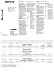
Motor protection fuse setting:
Motor schutz Einstetlung:
Rèlage du fusible protégeont le moteur:
U
/
f
Fl/A
F2/A
F3/A
F4/A
200/50
0.4
0.96
4.8
5.1
200/60
0.4
0.96
4.0
4.8
220/50
0.4
0.96
4.5
4.7
220/60
0.4
0.96
4.5
4.7
380/50
0.23
0.55
2.6
2.7
415/50
0.23
0.55
2.5
2.6
440/60
0.23
0.55
2.6
2.7
480/60
0.23
0.55
2.5
2.6
500/50
0.18
0.5
2
2.1
440/50
Motr.:
OverfLbeh.:
Mâftorhold:
lkke ang. tol. efter
DS/ISO 2768—
C: F3 og F4 opdaterst
for 200, 415 09 480
18/11—98 CVE
7
B: F2/A cUe v~rdier
Bndr. undt. 500/50
040196 BMJ/JTV
A: 200V/50+6Otitf.
090392 BRH/JTV
I
Projektionsmetod
‘#
StI’jei’s
Indstilling af termosikring
Abrapol—2
~
Tegn:
Kontr.
Dato
I
Ii 7O889~
Sign.
1 70889i v.H.
Erst.:
1 422 1 0450