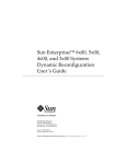
1
operation manual
service manual
Xenon XL-A180
180 Watt-Xenon-high-intensity lightsource
with automatic intensity control
and lamp-life-time indicator
Xenon XL-M180
180 Watt-Xenon-high-intensity lightsource
with manual intensity control
operation manual XL-A180 / XL-M180
table of contents
1
page 1
Safety reference / Place the equipment ______________________________________________________2
1.1
Safety reference.......................................................................................................................................... 2
1.2
Place the equipment ................................................................................................................................... 2
2
General advises / signs and symbols ________________________________________________________3
3
Description of the equipment_______________________________________________________________5
4
Operating elements _______________________________________________________________________6
4.1
Operating elements on the front panel........................................................................................................ 6
4.2
Operating elements on the rear .................................................................................................................. 7
5
Connecting and operating the equipment ____________________________________________________8
6
Service manual / Maintenance of the equipment ______________________________________________10
6.1
possible causes / remedy.......................................................................................................................... 10
6.2
Selection of the line voltage setting........................................................................................................... 11
6.3
Exchanging the mains fuses ..................................................................................................................... 11
6.4
Exchanging the lamp ................................................................................................................................ 11
6.5
Further maintenance in conjunction with lamp change ............................................................................. 12
6.6
Cleaning / Disinfecting .............................................................................................................................. 12
6.7
Wiring diagram.......................................................................................................................................... 13
7
Technical data __________________________________________________________________________16
8
Spare parts_____________________________________________________________________________16
9
Table ‘Technical service-information’ _______________________________________________________17
BA-E-neutral-XL180-2001-A.doc
operation manual XL-A180 / XL-M180
safety reference / place the equipment
1 Safety reference / Place the equipment
1.1 Safety reference
normal use
The equipment may only be used with accessories, wearing parts and disposable items, which have
been designated by the manufacturer as suitable for the instrument or the safety use of which is
proven.
user qualification
The equipment may only be used by persons, who have a corresponding specialised qualification
and who have been instructed in use of the equipment.
It is the user’s responsibility to make sure, the equipment is safe and operates properly before using
the equipment.
1.2 Place the equipment
unpacking / items included
Carefully unpack the equipment and accessories and remove it from their packing.
Check for missing items and evidence of shipping damage.
File any complaints with the manufacture or supplier immediately.
Retain the original packing materials for later use. These can come in handy, when the equipment
must be transported.
Please verify immediately after having unpacked the equipment, whether the delivery is complete.
The standard extent of delivery includes of the following:
• light source
• mains cable
• user manual
• video cable Y/C / BNC (only XL-A)
safety precautions at the site of installation
•
•
•
•
•
•
•
•
•
Always place the equipment on a solid base.
Make sure, that air circulation is sufficient.
Never cover the louver type slots of the unit.
The equipment may be used only in rooms having electrical installations conforming to
applicable national, state and local electronically codes.
The unit must be joined to the central potential equalisation of the operating theatre or of
the equipment trolley by means of a grounding cable.
The device must be connect to line voltage using the delivered protectively earthed power
supply cord.
The equipment may not be used in areas, where there are dangerous flammable gases.
The equipment may only be connect to devices, which also comply to the IEC601-1.
Never look direct in the lightbeam of a light source.
page 2
operation manual XL-A180 / XL-M180
general advises / signs and symbols
page 3
2 General advises / signs and symbols
Thank you for your expression of confidence in the manufacturers brand name.
Like all of our other products, this product is the result of years of experience and great care in
engineering and manufacture.
This manual is destined to learn you understanding the function and the operation of your
equipment.
Before you switch on the equipment for the first time, please thoroughly read this manual and pay
special attention to all safety instructions, so that endangering for the user and the patient is
precluded.
Please always store this manual with the equipment.
data of the equipment
The type label (rear of unit) contains technical data, type and serial
number of your unit. Please always indicate these data when ordering
spare parts or in case of any question.
Serial No.: ___________________
Please enter here the technical data of your device! Î
Date: _______________________
Type: _______________________
Class: ______________________
Hz:_________________________
Amp.:_______________________
Volt: ________________________
warranty
1 year according to our warranty conditions.
Opening the equipment or performance of any repairs or modifications of the equipment by
unauthorised persons shall relive the manufacturer of any liability for its performance. Any such
opening, repair or modification performed during the warranty period shall void all warranty.
Wear parts are not included in the warranty.
The firm of the manufacturer shall be liable for failure or deterioration in the safe operation,
operational reliability and performance of this equipment only subject to the conditions, that all
assembly operations, system expansions, readjustments or repairs to same have been performed
by a person or persons duly authorised by the manufacturer, that all electrical installations at the
location of us meet applicable national and local electrical codes and that the instrument has been
used in accordance with its operating instructions at all times.
operation manual XL-A180 / XL-M180
general advises / signs and symbols
rights
All rights on this user manual, especially the rights of duplication and publication and the rights on
translation are reserved. No part of this user manual may be reproduced by any means (by photo
static copy, microfilm or other methods) without preceding written consent of the manufacturer or
be reproduced, multiplied or published by means of electronic data processing.
The information given in this user manual can be changed or extended without notice and do not
represent any liability.
Errors and technical changes excepted.
©
symbols
attention, important note!
safety note!
service
signs
please read the enclosed instructions
unit model BF
beware of dangerous electrical voltage
connection for ground potential
~
alternating voltage
page 4
operation manual XL-A180 / XL-M180
description of the equipment
3 Description of the equipment
This light source is a high intensity 180 Watt XENON light source, which is designed for use in
every endoscopic discipline.
The colour temperature of 5.600° Kelvin equals the colour temperature of daylight.
The light source can be used with every light guide system, by the simply exchangeable adapter.
A mechanical diaphragm is used to adjust the output intensity without any influence on the colour
temperature.
The equipment complies with the latest safety standards for medical products and is approved to
CE.
page 5
operation manual XL-A180 / XL-M180
operating elements
page 6
4 Operating elements
4.1 Operating elements on the front panel
Main switch
Remaining lamp
life indicator
(only XL-A)
Light guide
connector
Push bottons
increase / decrease
intensity
Push bottons
manual / automatic
mode (only XL-A)
Main switch
The control unit is turned on by switching the mains switch.
The mains switch has two different switching positions:
I
switched on
O
switched off
When the control unit is switched on, this is indicated by the up-light green lamp inside the switch.
Light guide connector
This connector is used to connect the light guide to the lightsource. There is an interchangeable
adapter screwed in. The adapter used has to match the light guide fitting you are using. Several
adapters for all types of light guides are available. Most of these adapters have an automatic snap-in
for the light guide.
Remaining lamp life indicator (only XL-A…)
Indicates the remaining life time of the XENON lamp. When you switch on the light source it will start
up with internal self-check. After 500 hours working time, the indicator ‘LAMP CHG’ will start flashing.
It is recommended to replace the lamp with a new lamp.
pushbuttons ‘INCREASE / DECREASE INTENSITY’
These buttons are used to adjust the intensity of the output in manual mode. If the mechanical
diaphragm is opened or closed completely a yellow light in the switch will indicate this.
pushbuttons ‘MANUAL / AUTOMATIC MODE’ (only XL-A…)
These pushbuttons are used to switch the light source between MANUAL and AUTOMATIC mode.
The actual mode is indicated by a green light in the switch.
operation manual XL-A180 / XL-M180
operating elements
4.2 Operating elements on the rear
Potential ground
connector
Fuse holder
Mains voltage connector
Mains voltage indicator
Potential ground connector
When running the equipment in rooms which comply to class 1 or 2E according to MedGV, the
light source must be joined to the central potential equalisation of the operating theatre or of the
equipment trolley by means of a grounding cable.
Mains voltage connector
This is the connector for mains voltage. Use only the added mains cable
mains fuses / voltage selector
This drawer contains the mains fuses. The window inside the drawer shows the currently selected
mains voltage. You have to control whether your mains voltage corresponds with the selection
shown in the window.
Video IN connector (only XL-A…)
Here you have to connect the external video source, to run the light source in automatic mode.
Use only one of the connections:
BNC for composit, VHS-signal
Y/C for S-VHS-signal
page 7
operation manual XL-A180 / XL-M180
connecting and operating the equipment
5 Connecting and operating the equipment
Before you connect the mains plug, check on the back of the equipment that the voltage indicated
(in the square panel above the mains socket) is the correct one.
voltage = 230VAC Æ indicator ‘230’
voltage = 115VAC Æ indicator ‘115’
If the incorrect voltage is indicated then the equipment may under no circumstances be connect.
Before connecting a light cable into a light source adapter of the equipment, please ensure that
you have the correct plug and adapter. A plug that is too long or too thin can for example be
pushed too far into the equipment, and can damage the sensitive diaphragm or lens inside. This
will result moreover in considerable loss of light, in the same way as a plug that is too short, or a
plug of the wrong diameter, because of the wrong position of the contacts at the light entry.
All wiring has to be done before switching on the equipment.
After switching on a light source and the ensuing ignition of the lamp, the equipment should remain
switched on for at least ¼ hour. A shorter shining period will considerably shorten the life
expectancy of the lamp! After switching off a light source however, it may be immediately switched
on again. A waiting period or cooling off period is not necessary.
CONNECT THE MAINS CABLE !
Use the delivered protectively earthed power supply cord to connect the control unit to the mains.
Please check before, whether the current voltage selection matches your local mains voltage.
CONNECT THE EXTERNAL INPUT DEVICES (only XL-A…)
As described before, there are several standards of videosignal available on the rearpanel.
Here you can connect external input devices.
If you are using standard VBS-signal (BNC-terminal), please always apply high-quality 75Ω-coaxial
cables.
If the external device has a switchable 75Ω-termination resistor, you should switch this on.
If you connect several devices in a row only the last device in the line needs to be terminated by
the termination resistor.
If the external device does not provide such a termination resistor, you should connect the coaxial
cable via a T-connection-adapter. The open end of the T-connection adapter is then terminated
with the 75Ω-resistor.
We recommend the use of the delivered S-VHS-cable.
CONNECT THE POTENTIAL EQUALISATION CONDUCTOR !
Join the terminal device for potential equalisation on the rearpanel with the central potential
equalisation of the operating theatre or of the equipment trolley.
CONNECT THE LIGHTCABLE
Connect the lightguide to the lightsource using a suitable adapter for your lightguide.
OPERATING
Switch on the equipment
After connecting the mains, the grounding conductor, the light cable and the endoscope,
the equipment is ready for use, and can be switched on at the mains switch on the front
panel. The green mains light (Power) inside the switch will light up. The lamp will
automatically ignite. It will burn with full power right from the start.
page 8
operation manual XL-A180 / XL-M180
connecting and operating the equipment
Setting the light intensity (MANUAL mode)
The light source will start in MANUAL mode.
The output of light can now be adjusted either stronger or weaker by the push buttons
(INTENSITY). Then intensity is adjusted by a mechanical diaphragm with the result that
the spectrum of white light does not change when dimmed. When the diaphragm is
completely open for maximum light intensity or completely closed for minimum light
intensity (when the respective key is pressed), this will be indicated by the yellow LED
light in the corresponding key.
Using the equipment with video-camera (only XL-A…)
Connections or wiring of the equipment: Besides the mains connection and the
connection of the light cable with endoscope, the video signal must now also be
connected to the external input device.
Setting mode (only XL-A…
With standard cameras, therefore, for automatic brightness control through the light
source, you set the mode AUTO by pressing the button AUTO, and the green LED in the
button then lights up. When you switch on AUTO, the electronics will also automatically
switch to an average brightness from then on.
Setting the brightness on the monitor screen in auto-mode
If the automatically set picture brightness is not sufficient, or if it is too bright, then
brightness can be adjusted brighter or darker by the button INTENSITY, as with manual
operation. When the brightness diaphragm on the light source is completely open or
completely closed, this will be indicated by the yellow LED light in the brightness buttons.
We remind you to leave the lamp burning for at least ¼ hour, because shorter burning
period will reduce the life expectancy of the lamp. After switching off the equipment, it
may immediately be switched on again. A cooling off or waiting period is not necessary.
page 9
service manual XL-A180 / XL-M180
spare parts
page 10
6 Service manual / Maintenance of the equipment
general maintenance and repair advice
The instructions and information given in this chapter are only for instructed personnel, who are
aware of the safety precautions necessary for repair and maintenance of medical electronic
devices.
ILO-electronic refuse any liability for unauthorised repair and modification.
The manufacturer will provide those circuit diagrams, itemised parts listings, descriptions, sets of
adjustment instructions and other items of available documentation to suitably qualified user
personnel duly authorised by the manufacturer for their use in repairing those components of the
equipment that have been designated by their respective manufactures as reparable.
Only the supply of such technical documentation relating to the equipment shall not be construed as
constituting manufacturer’s authorisation of user’s personnel, regardless of their levels of technical
training, to open or repair the equipment.
Explicitly exempted here from are those maintenance and repair operations described in this
manual.
6.1 possible causes / remedy
In any case of malfunction, you should check the wiring at first. Most errors are based on wrong
wiring.
The last column shows the referring chapter.
malfunction
possible reason
equipment doesn’t work
main switch doesn’t shining
equipment doesn’t
main switch shining
work
intensity adjustment doesn’t
work
lamp is flashing but not
ignited
life time indicator is not
working
remedial measure
line cable not connected
connect line cable
main switch off
both line fuses defective
wrong line voltage adjusted
lamp after changing wrong
connected
lamp defective
one line fuse defective
wrong line voltage adjusted
no signal from external video
device
front panel controller defective
wrong light guide in use
ventilator blocked or defective
turn main switch on
check line fuses / exchange
adjust right line voltage with fuse drawer
check connector of the lamp
lamp defective
power supply defective
clock board defective
change lamp
exchange power supply
exchange PCB
change lamp
check line fuses / exchange
adjust right line voltage with fuse drawer
check video in connection / external video in
device must be switched on
exchange of controller
exchange of light guide
check ventilator
service manual XL-A180 / XL-M180
spare parts
6.2 Selection of the line voltage setting
To set the correct voltage proceed as follows:
• PULL OUT THE MAINS PLUG!
• Using a small screwdriver or other sharp instruments, the black rectangular board above the
socket can be lifted out.
• The white panel with the fuse can be taken out and turned 180°, and then put back into the
fuse container.
• After that the rectangular fuse board can be put back (the small nose of the board facing
downwards) and firmly pressed until it has completely snapped in.
• Now the small white panel should show the correct voltage.
6.3 Exchanging the mains fuses
Mains fuses are located on the rear panel of the control unit, right above the mains terminal device
in a small drawer. If you need to exchange the mains fuses, proceed as follows:
• PULL OUT THE MAINS PLUG!
• Loosen the drawer by unfastening the two clamps located to the left and to the right of the
drawer with a peaked tool and pull out the drawer.
• Take out the fuses.
• Check the fuses. A blown fuse is indicated by the blackened glass cylinder or the visibly melted
fuse conductor. If necessary, check the fuse with an ohmmeter.
• Install the corresponding fuses.
• Re-install the fuse-drawer.
• Switch on the equipment again. If you have exchanged a defective fuse against a new one and the
fuse blows again, the unit has an error. In this case, you must return the device to your dealer for
testing and repair.
6.4 Exchanging the lamp
If the life time of The lamp has expired, it must be exchanged against a new one.
The lamp is especially stressed when switched on or off. Thus, it will blow when switching on or off
the lightsource.
In order to exchange the lamp, proceed as follows:
•
Switch off the equipment !
•
Pull out the mains plug !
•
Unscrew the five screws located on both sides and rear of the housing and lift off the cover !
•
If the lamp has burned right before, it may be still very hot. Let it cool down before proceeding
!
•
Disconnect the lamp connector
•
Loosen the hand screw and push up the lamp guard.
•
Pull out the lamp backwards out of its holder !
•
Insert a new lamp into the holder and close the lamp guard like before.
•
Reconnect the lamp cable !
•
RESET THE LIFE TIME INDICATOR by switching the little red switch on the clockboard into
the opposite position.
•
Install the cover. Take care, that the grounding cable of the cover is installed properly.
•
Fasten the cover with the screws, plug in the mains plug and switch on the equipment.
page 11
service manual XL-A180 / XL-M180
spare parts
page 12
top view
+ cable
- cable
knurled head
screw
lamp body
lamp guard
lamp plug
fixed jack
heat protecting filter
lens (optional)
6.5 Further maintenance in conjunction with lamp change
After operation, dust may have been sucked through the fan blades into the equipment, depending
on the conditions in the environment. This dust should be removed from the equipment with a
vacuum cleaner using a small nozzle attachment. Dust can sometimes cling quite firmly to the fan
blades. This should then be cleaned with a cloth and a little alcohol/spirits. Likewise dust settles on
the heat protective filter, this should also be cleaned with a soft cloth or blotting paper and pure
alcohol or spirits.
Concerning use of flammable liquids, pay attention to safety precautions.
6.6 Cleaning / Disinfecting
NOTE: PULL OUT THE MAINS PLUG!
All parts of the outer surfaces of the equipment are totally insensitive to all the usual cleaning and
disinfecting materials, so that you can use any of these without limitation. Apply liquids using a soft
cloth or soft blotting paper, in order to avoid scratches on the surfaces and in order to be able to
control the amount of liquid.
With flammable liquids like alcohol especially, you should apply with a cloth. Do not let any liquid get
into the equipment. After cleaning with flammable liquids, leave the equipment to dry for one hour,
before it is switched on again. There is danger for example that an alcohol-air explosive mixture
could form after cleansing.
service manual XL-A180 / XL-M180
spare parts
6.7 Wiring diagram
page 13
service manual XL-A180 / XL-M180
spare parts
Power supply
Front panel controller (XL-A...)
page 14
service manual XL-A180 / XL-M180
spare parts
Front panel controller (XL-M...)
Starter board
page 15
Clock board (only XL-A...
service manual XL-A180 / XL-M180
spare parts
page 16
7 Technical data
Mains voltage
c 230 VAC ± 10%
d 115 VAC ± 10%
Power consumption
270 W
Mains fuses
fine fuses, 5x20mm
c 2x T2,5 A
d 2x T5 A
lightguide connector
all lightguides connectable using
interchangeable adapters
lamp
protective class
Xenon high pressure lamp 180 Watt / 5600°K
OSRAM XBO R180W/45C
BF
certificates
CE
manufacturer
ILO electronic GmbH, Quickborn
dimensions
355x110x325 mm (WxHxD)
weight
8,5 kg
8 Spare parts
Lamp
OSRAM XBO R180W/45C
Fuses
Fine fuses, 5x20 mm
mains fuses
Power supply
Starter board XL100/180
Front panel controller automatic
Front panel controller manual
Clock board
230 VAC: 2x T 2,5A
115 VAC: 2x T 5A
service manual XL-A180 / XL-M180
table ‘technical service-information’
page 17
9 Table ‘Technical service-information’
date
check
signature