1
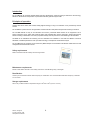
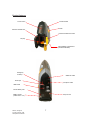
icountBS User Manual Issue K, 05 Aug 08 © Parker Hannifin, 2008 www.parker.com/eurofilt Laser Information This product contains an invisible infrared 5mW laser. Any dismantling of the product may result in dangerous exposure to laser radiation. DANGER INVISIBLE LASER RADIATION WHEN OPEN. AVOID DIRECT EXPOSURE TO BEAM. Please note that users are not required to access the laser radiation source and should never do so. Issue K, 05 Aug 08 © Parker Hannifin, 2008 www.parker.com/eurofilt 2 Contents LASER INFORMATION – Page 2 INTRODUCTION – PRINCIPLES OF OPERATION – Page 4 Page 4 BENEFITS – Page 5 TECHNICAL SPECIFICATION – Page 6 PRODUCT FEATURES – Page 7 PRODUCT DIMENSIONS – WORKING AND TESTING – Page 8 Page 8 THE EFFECT OF SYSTEM CONDITIONS – FLUID SAMPLE EXTRACTION – SAMPLE HANDLING AND PREPARATION – Page 9 Page 9 Page 9 A) TOUCH SCREEN INSTRUCTIONS – B) PRODUCT SET-UP – C) PRODUCT REGISTRATION – Page 11 Page 11 Page 11 D) HOME SCREEN OVERVIEW – E) CONFIGURATION – Page 12 Page 12 F) TO START A TEST – Page 14 G) DEFAULT TEST PARAMETER Page 14 H) NEW TEST SCREEN (PERFORM A TEST) – Page 15 I) REVIEW TEST DATA J) PERFORM ANOTHER TEST - Page 16 Page 17 K) BROWSE PREVIOUS TESTS - Page 17 L) EXPORTING TEST DATA – Page 18 M) DELETE TEST DATA – N) BROWSE OPTIONS – Page 19 Page 20 INTERPRETING DATA – Page 21 TROUBLESHOOT GUIDE – Page 28 PART NUMBER MATRIX – Page 30 Issue K, 05 Aug 08 © Parker Hannifin, 2008 www.parker.com/eurofilt 3 Introduction The icountBS with its innovative industrial design has been developed for customers looking for state of the art technology, attention to detail and the compactness of a permanent laboratory particle analysis model. Principles of operation Combine this with on-board, laser based, leading-edge technology to bring to all industries a truly revolutionary Particle Counter. The icountBS is a product from the next generation of Parker Hannifin’s fluid particle analysis and monitoring innovations. The icountBS features an easy to use interactive touch screen, pressurized bottle chamber for air suppression via an internal compressor pump, bottle cavity aperture design with automated door closure mechanism, sample tube cleaning sleeve minimizing contamination cross over (competitor shortfall), internal printer and is self-calibrating to ISO standards. Accredited to US Standards and achieving full ISO certification and calibration to the latest ISO Medium Test Dust Standards, icountBS represents the most up to date technology in solid particle contamination analysis. The icountBS brings to all industry a truly revolutionary Bottle Sampler as a remarkable cost effective market solution to fluid management and contamination control. Safety requirements Refer to the Parker Hannifin Quality and Servicing booklet. Maintenance requirements Please contact Parker Hannifin in the unlikely event of the icountBS being faulty or damaged. Recalibration Contact your local Parker Hannifin Sales Company for recalibration. The recommended recalibration frequency is between 12–18 months. Storage requirements o o Store in dry conditions within a temperature range of -40 C to + 90 C (-40°F to +194°F) Issue K, 05 Aug 08 © Parker Hannifin, 2008 www.parker.com/eurofilt 4 Benefits • Quick sample bottle analysis with variable test time options from 15 second and volume capacities from 10ml. • Repeatable and re-producible result performance to ISO11171 and NAS1638 particle count distributions. • Design concept allowing for portability. DC and rechargeable battery pack power options. • Cost-effective and economical alternative solution to external laboratory services. • 6 variable channel size analysis • Fluid resistant touch type screen panel • Sample tube self cleaning sleeve minimizing contamination cross over • Internal printer Issue K, 05 Aug 08 © Parker Hannifin, 2008 www.parker.com/eurofilt 5 Technical specification Fluid management Test Time Laser based light obscuration MTD or ACFTD H=525mm x W=180mm x D=410mm 18Kg Stainless steel 316, plated mild steel and aluminium Precision polyurethane RIM mouldings and ABS plastic o o +5 C to + 60 C 20 – 85% (Tested at 30oC, No condensation) -40oC to + 90oC o 10 – 90% (Tested at 30 C, No condensation) ACFTD - >2μ,>5μ,>15μ,>25μ,>50μ,>100μ MTD - >4μ(c),>6μ(c),>14μ(c),>21μ(c),>38μ(c), >70μ(c) ISO 7 to 21, NAS 0 to 12 ACFTD - ISO 4406:1987, ISO 4406:1991 & NAS 1638 MTD - ISO 4406:1999, NAS 1638 ACFTD - Fully traceable to gravimetric first principles. MTD - Traceable to ISO11171 via ISO11943*. 60ml/min Variable – depends on user selection of flush volume and test sample volume. Languages English and Japanese only. Pre-Test Flush Volume Possible Test Sample Volume Configurations System Flow Rate Viscosity Range Fluid Compatibility Sample Bottle Size Minimum = 10ml, Maximum = 100ml User selectable from single test up to 5 tests per run. (eg.1x100ml up to 5x10ml per run) Test = 60ml/Min, Exhaust =240ml/Min 10 to 400 cSt Mineral based oils. No specific bottle required. Maximum size = Ø75mm x 150mm height Maximum Volume Sample = 250ml Memory Storage Maximum of 500 tests. Test can be exported to USB memory stick. The data can then be read by Microsoft Excel. Hitachi touch screen display Backlight 256 colour STN transmissive Resolution - 320x3 (R.G.B) (H) x 240(W) dots 115(H) x 86(W) mm Windows CE Via icon on touch screen Thermal dot-line printing Paper rolls - Ø50mm x 57mm/60mm length x 25m long Yet to be established. DC Output – 12V @ 6.60 Amps, 80 Watts max. AC Input – 100 to 240V @ 1.2Amps (50 – 60 Hz) Principle of Operation Calibration Dust Dimensions Weight Mechanical Composition Plastics Composition Operating Temperature Operating RH range Storage Temperature Storage RH range Channel Sizes Analysis Range Contamination Standards Calibration Standard Output Display Display Active Area Operating System Data Input Printer Printer Paper Test Certification Power Supply Battery Power Battery Stand-by Time Battery fuse Air pressure Source 2 hours (recommended to be fully charged every 3 months) 1 month (then 1 hour of operation) 6.3 Amps (Anti Surge) 3.5 bar Mini-compressor OR 7 bar shop air. * (For full ISO 11171 calibration, consult Parker Hannifin) Issue K, 05 Aug 08 © Parker Hannifin, 2008 www.parker.com/eurofilt 6 Product features Touch screen Product handle Printer Pressure chamber door Pressure chamber door latch Drip tray Internal Battery compartment (located underneath) Emergency Air Dump Waste Oil Outlet 12vdc Input Oil Vapour Outlet USB socket Internal battery fuse Shop Air Inlet Battery On/Off (Switch down = On) Issue K, 05 Aug 08 © Parker Hannifin, 2008 www.parker.com/eurofilt 7 Product Dimensions Working and Testing The icountBS is capable of degassing and supplying a fixed amount of oil to test. Because of this it is able to eliminate many of the variables associated with contamination monitoring. The oil sample is degassed using compressed, cleaned air and then supplied, through a fixed displacement pumping system. Its test method is consistently controlled, thus removing more of the variables, which could occur with Bottle Sampling. Unfortunately, there are other factors that are beyond the control of Parker Hannifin products, consideration of which could result in error limitation. These are categorised as: THE EFFECT OF SYSTEM CONDITIONS. FLUID SAMPLE EXTRACTION. SAMPLE HANDLING AND PREPARATION. In most instances, the adoption of simple controlled procedures will result in reliable trend monitoring. Issue K, 05 Aug 08 © Parker Hannifin, 2008 www.parker.com/eurofilt 8 The Effect of System Conditions System flow rate Samples are best taken from a point in the system where the flow is TURBULENT (Reynolds No. greater than 4000). The turbulent flow creates a mixing action. Where the flow is streamline or LAMINAR, larger particulate may tend to settle toward the lower pipe surface and not be sampled. System Condition Changes Changes in the system operating condition, flow, temperature, pressure or vibration can result in previously sedimented contaminant being retained into the flowing oil. It is also possible that these changes may cause partially contaminated filter elements to shed particulate into the system. Samples should therefore, be extracted when the system is in a steady state condition and the result less likely to be distorted by contaminant peaks. Taking a Sample Extract a sample while the system is operating under consistently controlled conditions. Adopt a consistent technique. Spill off at least 200ml of fluid to flush the sampling port of residual contaminant. Leave bottle capped until ready to extract the sample. Fill the bottle to approximately 80% and cap immediately after extracting the sample. Fluid Sample Extraction Flow Rate Variations in the sampling flow rate may affect the result from bottle samples. The flow rate through a sampling port from an operating hydraulic system will vary dependant upon the system pressure, the port restriction and fluid viscosity. For best trend monitoring, it is necessary to maintain these conditions consistently when extracting Bottle Samples. Sampling Valves There are a number of proprietary sampling valves available, which adhere to good theoretical principles. However, they do tend to generate a level of precision and cost which is unnecessary for trend monitoring. Sampling points Sampling points should enable extraction of a sample without changing the system’s condition. Fine control needle valves are not desirable, as they have a tendency to silt up under some operating conditions, causing the distribution of contaminants in the fluid to be changed. The sampling port should be protected to maintain cleanliness and thoroughly flushed before collecting the sample for analysis. Sample Handling and Preparation Bottle Cleanliness It is preferable that bottles have sealing screw caps and both parts are cleaned to a suitable level in accordance with ISO3722. The bottle should not contain more than one tenth of the number of particles per 100ml than are expected to be monitored. Standard Parker Hannifin bottles are supplied clean to ISO 13/11 or better in a Class 10,000 Clean Room and should not be used to accurately count oils cleaner than ISO 16/14 although they may be used for “trend monitoring” at lower levels. NOTE: A Class 10,000 clean room is designed to never allow more than 10,000 particles (0.5 microns or larger) per cubic foot of air. So as you can quantify this, a typical office buildings' air contains between 500,000 to 1,000,000 particles (0.5 microns or larger) per cubic foot of air. The bottle should remain capped until time of sample filling and be re-capped immediately afterwards. Issue K, 05 Aug 08 © Parker Hannifin, 2008 www.parker.com/eurofilt 9 Sample Mixing Sedimentation of contaminant in a sample will occur, the rate of which is dependent upon both the fluid and particle characteristics. Methods of sample agitation have not been provided, as they are likely to inconsistently distort the analysis of results. Samples should be analysed, without delay, once agitated. Where facilities are available, mixing can be achieved using “paint shakers” and/or an ultrasonic bath (for example, 5 minutes with a paint shaker, 30 seconds in an ultrasonic bath and a further 15 minutes with the paint shaker, as indicated in ISO4402:1991[E]). Care should be taken when using ultrasonic baths to avoid distortion of the result by extended use, causing contamination breakdown. Bottle samples can be sufficiently stirred by swirling and tumbling by hand. Results The first result from a bottle sample should be disregarded, as it could be distorted by fluid from a previous sample. To reduce the effects of mixing variations and sedimentation, it is preferable to average the results of three tests. Individual users may establish the possibility to reduce this number of tests, dependant upon their requirements and experiences. Samples from different parts of a system will give different results. Consideration should be given to what monitoring is desired and where samples are to be extracted from for suitable trend monitoring to be performed. It is important that whatever practices are adopted by the user, they are performed consistently. Issue K, 05 Aug 08 © Parker Hannifin, 2008 www.parker.com/eurofilt 10 A) Touch screen instructions The icountBS is operated via the touch screen on the front of the product. Features are chosen by simply pressing the required icons on the screen. Common icons used: - return to the main screen - Returns to previous screen. - Prints selected data. B) Product set-up 1. Using the supplied clear waste tube, connect the waste bottle to the ‘WASTE OIL’ connection on the rear panel of the icountBS. 2. Using the supplied blue vapour tube, connect the waste bottle to the ‘OIL VAPOUR’ connection on the rear panel of the icountBS. 3. If available, Parker Hannifin recommends connecting shop air to ‘SHOP AIR’ inlet on rear panel on icountBS. If not the icountBS will operating using the internal compressor. 4. Open the pressure chamber door by pulling the yellow door latch. Note that the chamber door will not open if the chamber is pressurised. Ensure that the door seal is correctly seated and dust/dirt free. 5. Ensure the battery switch is ‘ON’ (switch in the DOWN position) 6. Connect the supplied power supply to the 240V mains supply and switch on. 7. Connect the supplied power supply jack plug to the ‘12vdc INPUT’ connection on the rear panel of the icountBS. After approximately 25 seconds, the icountBS touch screen will activate and perform a 20 seconds self test. 8. On initially powering up the iBS a language selection screen appears. Once the language of choice is selected this screen will not be seen again. It will, however, be possible to change the language, if desired, through the ‘Config’ System Settings option at a later point. 9. The icountBS is now ready for use. C) Product Registration The icountBS “Product Registration” screen may appear. The product needs to be activated. Please select one of the three on-screen options: 1. Visit www.parker.com/reg to obtain your registration key. Enter this key on the icountBS screen and then press “Reg Now” 2. Press “Skip” and start the 30 days grace 3. To simply turn the icountBS off, press “Turn Off” D) Home Screen overview Issue K, 05 Aug 08 © Parker Hannifin, 2008 www.parker.com/eurofilt 11 Home screen a a. b. c. d. b c d “Switch Off” – switches the icountBS off. The product can be re-activated by opening or closing the chamber door. “New Test” – perform a test. “Browse Tests” – displays previously saved tests. “Config” – displays the icountBS “System Settings” screen. E) Configuration (Config) System Information: Home screen “System Info” screen “Config” screen “System Info” – display system information regarding the icountBS. “Version” and “Build” refers to the installed icountBS software. Issue K, 05 Aug 08 © Parker Hannifin, 2008 www.parker.com/eurofilt 12 Date / Time: Home screen “Date / Time” screen “Config” screen a b c d e a. b. c. d. e. To set the “Time” – select either the hour or minute then press “Arrows” to adjust. To set the “Date” – select the day, month or year then press “Arrows” to adjust. To set the “Date Format” – select the current format. Three options will then be shown – 1. dd/MM/yyyy, 2. MM/dd/yyyy or 3. yyyy/MM/dd To set the “Time Format” – select the current format. Two options will then be shown – 1. 24-Hour or 2. AM/PM Press “Save” to save settings. Language: Home screen Language screen “Config” screen a a. To set the language as “English” press the Union Flag. b. To set the language to “Japanese” press the Nishoki. Issue K, 05 Aug 08 © Parker Hannifin, 2008 www.parker.com/eurofilt 13 b F) To start a test 1. Ensure the ‘Product set-up’ procedures are carried out. 2. Ensure that the required test sample bottles are close to hand. 3. Open the pressure chamber door by pulling the yellow door latch. Note that the chamber door will not open if the chamber is pressurised. 4. Apart from the drip tray, ensure the chamber is empty. 5. Remove the drip tray from chamber. 6. Remove the cap from the test sample bottle. Place the sample bottle onto the drip tray. 7. Reposition the drip tray (and test sample bottle) into chamber. Note it is necessary to tilt the test sample bottle slightly backwards on the drip tray so that it clears the icountBS sample steel dip tube (located inside the pressure chamber, top surface). Ensure the test sample bottle is located centrally on the drip tray and that the icountBS sample tube (located inside the chamber) does not collide with the sample bottle when the icountBS operates 8. Close the chamber door then re-lock using the yellow door latch. 9. The icountBS is now ready to be operated via the touch screen. IMPORTANT WHILST TESTING, ENSURE THE WASTE BOTTLE OIL LEVEL IS MONITORED TO PREVENT OVERFLOWING. G) Default Test Parameters Test parameters screen Issue K, 05 Aug 08 © Parker Hannifin, 2008 www.parker.com/eurofilt o Bottle ID – Bottle-xxx (where xxx = sequential number, e.g. 001, 002, 003) o Standard – ISO 4406:1999 o Flush Volume – 15ml o Number of Samples – 3 o Volume of Sample – 50ml o Print Result – Don’t Print 14 H) New Test Screen (Perform a test) Test in progress screen Test parameters screen Home screen b c d e f g h a a. i j Press ‘New Test’ The ‘Test Parameters’ screen will appear. The parameters fields shown are all user definable. By selecting/pressing the relevant parameter field, either an options panel or QWERTY style keyboard will be displayed. b. c. d. e. f. g. h. i. j. “Bottle ID” – Test sample bottle identification. Accept the default or type the required bottle identification, remembering to press enter on the keyboard. Note that after this test is completed, the bottle ID will revert back to the default ID. “Standard” – Select between different Contamination Standards. “Flush Volume” – Total volume of fluid to be flushed through the icountBS before the sample test is performed. “Number of Samples” – The total number of samples to be taken from the one test sample bottle. ”Volume per Sample” – Total volume of fluid to be take from test sample bottle. “Print Result” – Option to print test result after the sample test. “Start Test” – will start a sample test to the current Test Parameters. The ‘Test in Progress’ screen will appear. “Default” – will reset the icountBS Test Parameters to the factory test parameter defaults:“Abort” – will abort the current test. Occasionally the icountBS will require a re-boot to recover from the abort test command. Simply switch the mains / battery supply off, wait approximately 5 seconds and then switch back on. Note: The internal pump capacity is 110ml The maximum Test Volume is 250ml (i.e. Flush Volume + Volume per Sample x Number of Samples = 250ml) If multiple samples are required from one sample bottle and the combined Flush Volume & Volume per Sample is greater than 110ml, then the pump will empty to the connected waste bottle before drawing the next sample. The icountBS will perform an AMF (Automatic Mini-Flush) of approximately 5ml at the end of the first Volume per sample and then again at the beginning of the next Volume per Sample. However, if the Flush Volume and Volume per Sample is LESS than 110ml (the internal pump capacity) then the test samples are combined (see Example B). Example A: The icountBS unit has been configured – Flush Volume = 10ml, No of Samples = 3, Volume per sample = 60ml Volume per Sample (ml) 10 1 60 2 5* 60 3 5* 60 20 180 Total * A utomatic M ini- F lush Sample number Issue K, 05 Aug 08 © Parker Hannifin, 2008 www.parker.com/eurofilt Flush Volume (ml) AMF* (ml) Approx. Actual Test Sample Volume (ml) 5 5 10 75 70 65 210 15 Example B: The icountBS unit has been configured – Flush Volume = 20ml, No of Samples = 3, Volume per sample = 50ml Volume per Sample (ml) 20 1 50 2 5* 50+50 3 25 150 Total * A utomatic M ini- F lush Sample number Flush Volume (ml) AMF* (ml) Approx Actual Test Sample Volume (ml) 5 5 75 105 180 I) Review New Test Data On completion, the test result is shown. Test bottle screen a a. b. c. Test bottle counts screen b Test bottle screen c Select “Show Counts” to review test counts. On the test counts screen, if the test has more than one measured sample, then press/select the page through the total and each sample. Select “Show Bottle” to review test bottle detail (return back to the original screen). and to The test data is automatically stored on the icountBS (refer to section K for instructions to browse test data). The icountBS is limited to 500 stored tests. By default, the icountBS will warn the user from the 450th test to export or th delete test data. At the 500 test, the user has no further option but to export / delete test data. Refer to section N of this manual to change this setting. Issue K, 05 Aug 08 © Parker Hannifin, 2008 www.parker.com/eurofilt 16 J) Perform Another Test Straight after review the test data it is possible to perform another test – assuming that there is plenty of fluid left in the sample bottle. Test bottle screen Test parameters screen a a. Press “New Test” to perform another test and display the ‘Test Parameters’ screen. Refer to section H of this manual. K) Browse Previous Tests The review / browse previously stored tests. Home screen Test bottle screen Browse Test screen b c a a. d Press “Browse Tests” to browse previous tests. The browse test screen will be displayed. Note the test names displayed on this list are individual tests that have been stored on the icountBS. b. c. d. Select / highlight the required test. Select the standard to be displayed. “As Tested” is the default value and will display the selected test in the standard it was originally tested in. Other standards are available to view tests in a different standard to the original. Press “Show” to display the sample test bottle details. Refer to section I of this manual to review the counts for this particular bottle. Issue K, 05 Aug 08 © Parker Hannifin, 2008 www.parker.com/eurofilt 17 L) Exporting test data Export one test Ensure that a USB memory pen is connected to the rear of the icountBS. Browse Test screen a b a. b. Select / highlight the required test. Press “Export”. A Microsoft Office Excel Comma Separated Values File (.csv) is automatically saved to the USB memory pen. Note that a directory named ‘icountBS’ is created on the root directory of the USB memory pen. The exported .csv file(s) are located here. Export multiple tests Ensure that a USB memory pen is connected to the rear of the icountBS. Browse Test screen c c d c. d. Individually press/select the required test files Press “Export”. A Microsoft Office Excel Comma Separated Values File (.csv) is automatically saved to the USB memory pen. Note that a directory named ‘icountBS’ is created on the root directory of the USB memory pen. The exported .csv file(s) are located here. Issue K, 05 Aug 08 © Parker Hannifin, 2008 www.parker.com/eurofilt 18 Export all stored tests Ensure that a USB memory pen is connected to the rear of the icountBS. Browse Test screen e f g e. f. g. Individually press/select the required test files Press/select “Select All” Press “Export”. A Microsoft Office Excel Comma Separated Values File (.csv) is automatically saved to the USB memory pen. Note that a directory named ‘icountBS’ is created on the root directory of the USB memory pen. The exported .csv file(s) are located here. M) Delete test data Please note that once the test data is deleted, this information is unrecoverable from the icountBS. Browse Test screen a a b a. b. Select / highlight the required test(s) OR press “Select All”. Press “Delete”. Issue K, 05 Aug 08 © Parker Hannifin, 2008 www.parker.com/eurofilt 19 N) Browse Options The browser on the icountBS can be reconfigured to the suit the users requirements. For example, sort by date, sort by name, etc. Options screen Browse Test screen b c d e a a. b. c. d. e. f g Select “Options” Sort Results By “Date”, then select either “Most Recent First” or “Oldest First” OR Sort Results By “Name”, then select either “A-Z” or “Z-A” to sort alphabetically. Select the “Filter Results By Date” tick box to allow the user to search between stored test dates. This option allows the user to select “All” test data or test data that has already been “Exported” and test data that has “Not Exported”. Select either option if required. Issue K, 05 Aug 08 © Parker Hannifin, 2008 www.parker.com/eurofilt 20 Interpreting data Solid contaminants in fluid power systems vary in size, shape, form and quantity. The most harmful contaminants are normally between 6 microns and 14 microns. The ISO code is the preferred method of reporting quantity of contaminants. The ISO code number corresponds to contamination levels pertaining to three sizes. Number of particles per 100 millilitres greater than indicated size The first scale number represents the number of particles larger than 4µm(c) per 100 milliliter of fluid, the second number for particles larger than 6 µm(c) per 100 milliliter of fluid and the third number for particles larger than 14 µm(c) per 100 milliliter of fluid. Particle size, µm Interpolation is acceptable; extrapolation is not permissible. Issue K, 05 Aug 08 © Parker Hannifin, 2008 www.parker.com/eurofilt 21 ISO contamination numbers Range number Number of particles per 100 ml More than 24 23 22 21 20 19 18 17 16 15 14 13 12 11 10 9 8 7 6 5 4 3 2 1 Up to and including 8 x 10⁶ 4 x 10⁶ 2 x 10⁶ 6 1 x 10 500 x 103 250 x 103 130 x 103 64 x 103 32 x 103 16 x 103 8 x 10³ 4 x 10³ 2 x 10³ 1 x 10³ 500 250 130 64 32 16 8 4 2 1 8 x 10⁶ 16 x 106 4 x 10⁶ 6 2 x 10 1 x 10⁶ 500 x 103 250 x 103 130 x 103 64 x 103 32 x 103 16 x 103 8 x 10³ 4 x 10³ 2 x 10³ 3 1 x 10 500 250 130 64 32 16 8 4 2 For example: code 20/18/13 indicates that there are between 500,000 and 1,000,000 particles larger than 2 microns, and between 130,000 and 250,000 particles larger than 5 microns, and between 4,000 and 8,000 particles larger than 15 microns. Reference ISO 4406:1999 When the raw data in one of the size ranges results in a particle count of fewer than 20 particles, the scale number for that size range is labelled with the symbol ‘>’. For example, a code of 14/12/>7 signifies that there are more than 8,000 and up to and including 16,000 particles equal to or larger than 4µm(c) per 100 ml and more than 2,000 and up to and including 4,000 particles equal to or larger than 6µm(c) per 100 ml. The third part of the code, >7 indicates that there are more than 64 and up to and including 130 particles equal to or larger than 14µm(c) per 100 ml. But the 14µm(c) part of the code could actually be 7, indicating a particle count more than 130 particles per 100 ml. Issue K, 05 Aug 08 © Parker Hannifin, 2008 www.parker.com/eurofilt 22 ISO4406 particle distribution chart Number of particles per millilitre greater than indicated size Number of particles per 100 millilitres greater than indicated size Including various ISO level contamination grades. Particle size, µm Issue K, 05 Aug 08 © Parker Hannifin, 2008 www.parker.com/eurofilt 23 NAS 1638 chart Classes (based on maximum contamination limits, particles per 100ml) Size range µm 00 0 1 2 3 4 5 6 7 8 9 10 11 12 5-15 125 250 500 1,000 2,000 4,000 8,000 16,000 32,000 64,000 128,000 256,000 512,000 1,024,000 15-25 22 44 89 178 356 712 1,425 2,850 5,700 11,400 22,800 45,600 91,000 182,400 25-50 4 8 16 32 63 126 253 506 1,012 2,025 4,050 8,100 16,200 32,400 50-100 1 2 3 6 11 22 45 90 180 360 720 1,440 2,880 5,760 >100 0 0 1 1 2 4 8 16 32 64 128 256 512 1,024 ISO/NAS/SAE comparison chart BS 5540/4 11/8 12/9 13/10 14/9 14/11 15/9 15/10 15/12 16/10 16/11 16/13 17/11 17/14 18/12 18/13 18/15 19/13 19/16 20/13 20/17 21/14 21/18 22/15 23/17 Defence Std. 05/42 Table A Table B NAS 1638 SAE 749 2 3 4 0 1 5 2 6 3 7 4 8 5 9 6 400F 400 800F 800 1,300F 1,300 2,000 2,000 4,400F 4,400 6,300F 10 6,300 11 15,000 12 21,000 100,000 The above comparisons relate to the particle count data only. To confirm to any particular standard, reference should be made to the recommended experimental procedure. Issue K, 05 Aug 08 © Parker Hannifin, 2008 www.parker.com/eurofilt 24 Component cleanliness guidelines Suggested acceptable contamination levels for various hydraulic systems. Target contamination class to ISO 4406 Suggested maximum particle level 6 µm 6 µm 13 15 14 µm 9 11 4,000 16,000 Sensitivity Type of system Typical components Super critical Slit-sensitive control systems with very high reliability. Laboratory or aerospace. High performance servo valves 1,000 Critical High performance servo and high pressure long life systems, e.g. aircraft, machine tools etc. Industrial servo valves High quality reliable systems. General machine requirements. Piston pumps, proportional valves, compensated flow controls 14 µm 250 16 13 32,000 4,000 Very important 18 14 130,000 8,000 Important General machinery and mobile systems. Medium pressure, medium capacity. Vane pumps, spool valves Gear pumps, manual and poppet valves, cylinders. Ram pumps 19 15 250,000 16,000 Average Low pressure heavy industrial systems, or applications where long lift is not critical. 21 17 1,000,000 64,000 Main protection Low pressure systems with large clearances. Issue K, 05 Aug 08 © Parker Hannifin, 2008 www.parker.com/eurofilt 25 ISO contamination charts Typical system applications and code numbers These typical applications and ISO code numbers are taken from the UK Contamination and Control Research Programme (1980 – 1984) Ref. AHEM Guide to Contamination Control in Hydraulic Power Systems - 1985 Solid Contaminant Code No 13/10 Number of particles per ml greater than indicated size Particle size µm Application: Aircraft test stands Number of particles per 100 ml greater than indicated size Solid Contaminant Code No 18/11 Number of particles per ml greater than indicated size Particle size µm Application: Mobile systems Number of particles per 100 ml greater than indicated size Solid Contaminant Code No 17/12 Number of particles per ml greater than indicated size Particle size µm Application: Marine installations Number of particles per 100 ml greater than indicated size Issue K, 05 Aug 08 © Parker Hannifin, 2008 www.parker.com/eurofilt 26 Solid Contaminant Code No 18/13 Number of particles per ml greater than indicated size Particle size µm Application: Mechanical handling Number of particles per 100 ml greater than indicated size Solid Contaminant Code No 16/11 Number of particles per ml greater than indicated size Particle size µm Application: Injection moulding; Metalworking; Unused commercial-grade oil Number of particles per 100 ml greater than indicated size Issue K, 05 Aug 08 © Parker Hannifin, 2008 www.parker.com/eurofilt 27 Troubleshoot guide Problem The chamber does not pressurise. Message appears - “System Fault code 5302 please switch off and try again” Cause The door seal may be split or dirty causing the chamber to leak under pressure. The door location pin has not engaged the door chamber handle. The chamber door latch has not engaged. The chamber door locking pin has not engaged Solution 1. Press “ok” on the touch screen to remove the System Fault message or abort the current test. 2. Open the chamber door and inspect door seal / seal groove. Clean, re-grease (with high vacuum 3. Whilst performing the test procedures again, check the alignment of door location pin against the 4. If the icountBS fails to recover, then contact Parker Hannifin. Problem Data can not be exported. Message appears - "USB Disk Not Found" Cause For exporting data, the icountBS requires an USB memory pen/stick to be connected. Solution 1. Connect a USB memory pen / stick to the USB port to the USB connection on the rear panel of the Problem The icountBS does not function (i.e. locked / frozen) Cause The sample bottle has not been centrally aligned with the dip tube inside the chamber. This has resulted in the dip tube being ‘wedged’ against the sample bottle. Solution 1. Switch the icountBS off and then re-start. 2. If the icountBS fails to recover, then contact Parker Hannifin. Issue K, 05 Aug 08 © Parker Hannifin, 2008 www.parker.com/eurofilt 28 Problem The icountBS compressor continuously runs. Cause System communication error. Solution 1. Switch the icountBS off and then re-start. 2. If the icountBS fails to recover, then contact Parker Hannifin. Problem Test counts are displaying ‘00000000’ Cause The counting sensor has not detected any particles. Solution 1. Switch the icountBS off then re-start and then perform another test. 2. If the icountBS still shows ‘0000000’ counts, then contact Parker Hannifin. Problem Total sample volume is more than 250ml Message appears - "Total volume require exceeds 250ml" Cause The maximum sample volume is 250ml (ie. Flush Volume + Volume per Sample x Number of Samples = 250ml max) Solution 1. Return to Test Parameters screen and re-enter. Problem Remains pressurised. Cause 1. Electrical failure 2. Mechanical failure. Solution 1. Remove Red Plug from the Emergency Air Dump Valve on the Rear Panel . WARNING!! Allow 5 seconds for the air to fully deflate before attempting to open the Door. A very small amount of air will remain in the Sample Chamber but the door can be safely opened. Issue K, 05 Aug 08 © Parker Hannifin, 2008 www.parker.com/eurofilt 29 Part number Matrix Key IBS Fluid Type 1 Calibration Mineral 1 ACFTD 2 Aggressive 2 MTD 3 Aviation Fuel Future Option Future Option Future Option 0 0 0 Moisture Sensor Power Supply Options 1 No 0 None 0 UK 2 - 1 - 1 USA 2 Europe Key Fluid Type Calibration Future Option Future Option Future Option Moisture Sensor Options Power Supply IBS 1 2 0 0 0 1 0 2 Accessories Part Number 250ml Sample Bottle Kit (Pair) Sample Bottle Pack (50 x B89911) Vapour / Waste Bottle ACC6NW001 Waste Bottle Folder Holder ACC6NW004 Printer Paper Reel (x1) ACC6NW005 ACC6NW002 ACC6NW003 UK Power Supply ACC6NW006 USA Power Supply ACC6NW007 European Power Supply ACC6NW008 Transit Case Contact Parker 1m waste tube (clear) ACC6NW009 1m vapour hose (blue) ACC6NW010 USB Memory Stick / pen ACC6NW011 icountBS CD Manual ACC6NW012 Issue K, 05 Aug 08 © Parker Hannifin, 2008 www.parker.com/eurofilt 30 Parker’s Motion & Control Technologies At Parker, we’re guided by a relentless drive to help our customers become more productive and achieve higher levels of profitability by engineering the best systems for their requirements. It means looking at customer applications from many angles to find new ways to create value. Whatever the motion or control technology need, Parker has the experience, breadth of product and global reach to consistently deliver. No company knows more about motion and control technology than Parker. FLUID & GAS HANDLING Key Markets ( Aerospace ( Agriculture ( Bulk chemical handling ( Construction machinery ( Food & beverage ( Fuel & gas delivery ( Industrial machinery ( Mobile ( Oil & gas ( Transportation ( Welding Key Products ( Brass fittings & valves ( Diagnostic equipment ( Fluid conveyance systems ( Industrial hose ( PTFE & PFA hose, tubing & plastic fittings ( Rubber & thermoplastic hose & couplings ( Tube fittings & adapters ( Quick disconnects AEROSPACE Key Markets ( Aircraft engines ( Business & general aviation ( Commercial transports ( Land-based weapons systems ( Military aircraft ( Missiles & launch vehicles ( Regional transports ( Unmanned aerial vehicles Key Products ( Flight control systems & components ( Fluid conveyance systems ( Fluid metering delivery & atomization devices ( Fuel systems & components ( Hydraulic systems & components ( Inert nitrogen generating systems ( Pneumatic systems & components ( Wheels & brakes HYDRAULICS Key Markets ( Aerospace ( Aerial lift ( Agriculture ( Construction machinery ( Forestry ( Industrial machinery ( Mining ( Oil & gas ( Power generation & energy ( Truck hydraulics Key Products ( Diagnostic equipment ( Hydraulic cylinders & accumulators ( Hydraulic motors & pumps ( Hydraulic systems ( Hydraulic valves & controls ( Power take-offs ( Rubber & thermoplastic hose & couplings ( Tube fittings & adapters ( Quick disconnects CLIMATE CONTROL Key Markets ( Agriculture ( Air conditioning ( Food, beverage & dairy ( "'*, !+',#+,! $ %,)'+-& ( Precision cooling ( Processing ( Transportation Key Products ( CO2 controls ( Electronic controllers ( Filter driers ( Hand shut-off valves ( Hose & fittings ( Pressure regulating valves ( Refrigerant distributors ( Safety relief valves ( Solenoid valves ( Thermostatic expansion valves PNEUMATICS Key Markets ( Aerospace ( Conveyor & material handling ( Factory automation ( Life science & medical ( Machine tools ( Packaging machinery ( Transportation & automotive Key Products ( Air preparation ( Brass fittings & valves ( Manifolds ( Pneumatic accessories ( Pneumatic actuators & grippers ( Pneumatic valves & controls ( Quick disconnects ( Rotary actuators ( Rubber & thermoplastic hose & couplings ( Structural extrusions ( Thermoplastic tubing & fittings ( Vacuum generators, cups & sensors ELECTROMECHANICAL Key Markets ( Aerospace ( Factory automation ( Life science & medical ( Machine tools ( Packaging machinery ( Paper machinery ( Plastics machinery & converting ( Primary metals ( Semiconductor & electronics ( Textile ( Wire & cable Key Products ( AC/DC drives & systems ( Electric actuators, gantry robots & slides ( Electrohydrostatic actuation systems ( Electromechanical actuation systems ( Human machine interface ( Linear motors ( Stepper motors, servo motors, drives & controls ( Structural extrusions PROCESS CONTROL Key Markets ( Chemical & refining ( Food, beverage & dairy ( Medical & dental ( Microelectronics ( Oil & gas ( Power generation Key Products ( Analytical sample conditioning products & systems ( Fluoropolymer chemical delivery fittings, valves & pumps ( High purity gas delivery fittings, valves & regulators ( Instrumentation fittings, valves & regulators ( Medium pressure fittings & valves ( Process control manifolds FILTRATION Key Markets ( Food & beverage ( Industrial machinery ( Life sciences ( Marine ( Mobile equipment ( Oil & gas ( Power generation ( Process ( Transportation Key Products ( Analytical gas generators ( Compressed air & gas filters ( Condition monitoring ( Engine air, fuel & oil filtration & systems ( Hydraulic, lubrication & coolant filters ( Process, chemical, water & microfiltration filters ( Nitrogen, hydrogen & zero air generators SEALING & SHIELDING Key Markets ( Aerospace ( Chemical processing ( Consumer ( Energy, oil & gas ( Fluid power ( General industrial ( Information technology ( Life sciences ( Military ( Semiconductor ( Telecommunications ( Transportation Key Products ( Dynamic seals ( Elastomeric o-rings ( EMI shielding ( Extruded & precision-cut, fabricated elastomeric seals ( Homogeneous & inserted elastomeric shapes ( High temperature metal seals ( Metal & plastic retained composite seals ( Thermal management Parker Worldwide AE – UAE, Dubai Tel: +971 4 8127100 [email protected] GR – Greece, Athens Tel: +30 210 933 6450 [email protected] RU – Russia, Moscow Tel: +7 495 645-2156 [email protected] AR – Argentina, Buenos Aires Tel: +54 3327 44 4129 HK – Hong Kong Tel: +852 2428 8008 AT – Austria, Wiener Neustadt Tel: +43 (0)2622 23501-0 [email protected] HU – Hungary, Budapest Tel: +36 1 220 4155 [email protected] SE – Sweden, Spånga Tel: +46 (0)8 59 79 50 00 [email protected] SG – Singapore Tel: +65 6887 6300 AT – Eastern Europe, Wiener Neustadt Tel: +43 (0)2622 23501 970 [email protected] IE – Ireland, Dublin Tel: +353 (0)1 466 6370 [email protected] SK – Slovakia, Banská Bystrica Tel: +421 484 162 252 [email protected] IN – India, Mumbai Tel: +91 22 6513 7081-85 SL – Slovenia, Novo Mesto Tel: +386 7 337 6650 [email protected] AU – Australia, Castle Hill Tel: +61 (0)2-9634 7777 AZ – Azerbaijan, Baku Tel: +994 50 2233 458 [email protected] BE/LU – Belgium, Nivelles Tel: +32 (0)67 280 900 [email protected] BR – Brazil, Cachoeirinha RS Tel: +55 51 3470 9144 BY – Belarus, Minsk Tel: +375 17 209 9399 [email protected] CA – Canada, Milton, Ontario Tel: +1 905 693 3000 CH – Switzerland, Etoy Tel: +41 (0) 21 821 02 30 [email protected] CN – China, Shanghai Tel: +86 21 5031 2525 CZ – Czech Republic, Klecany Tel: +420 284 083 111 [email protected] DE – Germany, Kaarst Tel: +49 (0)2131 4016 0 [email protected] DK – Denmark, Ballerup Tel: +45 43 56 04 00 [email protected] ES – Spain, Madrid Tel: +34 902 33 00 01 [email protected] FI – Finland, Vantaa Tel: +358 (0)20 753 2500 parker.fi[email protected] FR – France, Contamine s/Arve Tel: +33 (0)4 50 25 80 25 [email protected] IT – Italy, Corsico (MI) Tel: +39 02 45 19 21 [email protected] JP – Japan, Tokyo Tel: +(81) 3 6408 3901 KR – South Korea, Seoul Tel: +82 2 559 0400 KZ – Kazakhstan, Almaty Tel: +7 7272 505 800 [email protected] LV – Latvia, Riga Tel: +371 6 745 2601 [email protected] MX – Mexico, Apodaca Tel: +52 81 8156 6000 MY – Malaysia, Subang Jaya Tel: +60 3 5638 1476 NL – The Netherlands, Oldenzaal Tel: +31 (0)541 585 000 [email protected] NO – Norway, Ski Tel: +47 64 91 10 00 [email protected] TH – Thailand, Bangkok Tel: +662 717 8140 TR – Turkey, Istanbul Tel: +90 216 4997081 [email protected] TW – Taiwan, Taipei Tel: +886 2 2298 8987 UA – Ukraine, Kiev Tel +380 44 494 2731 [email protected] UK – United Kingdom, Warwick Tel: +44 (0)1926 317 878 [email protected] US – USA, Cleveland Tel: +1 216 896 3000 VE – Venezuela, Caracas Tel: +58 212 238 5422 ZA – South Africa, Kempton Park Tel: +27 (0)11 961 0700 [email protected] NZ – New Zealand, Mt Wellington Tel: +64 9 574 1744 PL – Poland, Warsaw Tel: +48 (0)22 573 24 00 [email protected] PT – Portugal, Leca da Palmeira Tel: +351 22 999 7360 [email protected] RO – Romania, Bucharest Tel: +40 21 252 1382 [email protected] European Product Information Centre Free phone: 00 800 27 27 5374 (from AT, BE, CH, CZ, DE, EE, ES, FI, FR, IE, IT, PT, SE, SK, UK) © 2008 Parker Hannifin Corporation. All rights reserved. Catalogue FDCB375UK 05/2008 Parker Hannifin Ltd. Hydraulic Filter Division Europe Condition Monitoring Centre Tel.: +44 (0) 1842 763299 Email: [email protected] www.parker.com/hfde Issue K, 05 Aug 08 © Parker Hannifin, 2008 Your local authorised Parker distributor