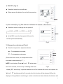
1
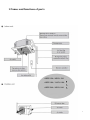
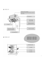
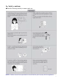
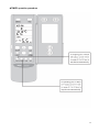
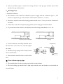
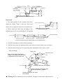
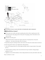
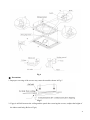
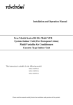
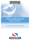
USER'S MANUAL
UNI ON/OFF SERIES
cassette units
ASCU-12A, ASCU-18A, ASCU-24A
ASCU-36A, ASCU-42A, ASCU-48A
Thanks for your selection of SINCLAIR Air-Conditioning Unit. Before use, please read this
instruction manual carefully and keep it properly to ensure correct use of this machine.
CONTENTS
1、Names and functions of parts…………………………………………………………………....1
2、Safety cautions…………………………………………………………………………………….3
3、Wire controller…………………………………………………………………………………….5
4、Remote control operation procedure…………………………………………………………….13
5、Weekly timer………………………………………………………………………………………23
6、Optimum operation………………………………………………………………………………25
7、Trouble shooting…………………………………………………………………………………..26
8、Installation notes………………………………………………………………………………….28
9、Care and maintenance…………………………………………………………………………….29
10、Instructions of unit installation…………………………………………………………………30
11、Test operation……………………………………………………………………………………50
Appendix…………………………………………………………………………………………...…52
1.Names and functions of parts ASGE-12A / ASCU-12A
ASGE-18A / ASCU-18A
ASGE-24A / ASCU-24A
B
B
B
1
ASGE-36A / ASCU-36A
ASGE-42A / ASCU-42A
ASGE-48A / ASCU-48A
2
2、Safety cautions
●Read the following carefully to assure safe use.
NOTE: Children should be supervised to ensure that they do not play with the appliance.
3
NOTE: This appliance is not intended for use by persons (including children) with reduced
physical, sensory or mental capabilities, or lack of experience and knowledge, unless they
have been given supervision or instruction concerning use of the appliance by a person
responsible for their safety.
4
3、Wire controller(standard fitting)
Never install the wire controller in a place where there is water leakage.
Avoid bumping, throwing, tossing or frequently opening the wire controller.
Fig.1
5
1) ON/OFF (Fig.2)
MODE
★ Press this button the unit will start.
★ When repress the button, the unit will stop running.
FAN
SWING
TIMER
ON/OFF
Fig 2
2) Fan control(Fig. 3) (The relevant contents are shown in the figure.)
★ Press this button to change the fan speed of:
MODE
FAN
★ At the DRY mode: the fan speed will be set for
SWING
TIMER
low fan speed automatically.
ON/OFF
Fig 3
3) Temperature adjustment(Fig.4)
★ Press the temperature adjustment button
▲:For temperature increase;
MODE
▼:For temperature decrease.
(Press this button once, the temperature will be
FAN
SWING
increased or decreased by 1℃.)
TIMER
ON/OFF
NOTE: Lock function: Press “▲” and ” ▼” at the same
time for 5 seconds, the set temp. indicating area shall
Fig 4
display “EE” and all keys’ response shall be shut off, all buttons will sound; and repress the
“▲” and ” ▼” simultaneously for 5 seconds, the lock function will be released. When the
displayer of long-distance monitoring or central controller has been shielded, the buttons and
6
remote control signal will be shielded too, the setting temp. will display “CC”.
★ The set temperature range under each mode:
HEAT -------- 16℃~30℃
COOL -------- 16℃~30℃
DRY -------- 16℃~30℃
FAN -------- The temp. cannot be set up
AUTO -------- The temp. cannot be set up
4)Swing mode set up(Fig.5)
★ When pressing “SWING" button, the type style
MODE
"SWING" will be displayed on LCD, the unit will run
in Swing mode
FAN
SWING
★ when repressing the “SWING” button, that the type
TIMER
ON/OFF
style "SWING" will be disappeared, and the unit will
stop running in Swing mode.
Fig 5
Note: The SLEEP function could be set up by wireless remote control.
5) Running mode setup(Fig.6)
★ When press this button once, the operation mode will
MODE
be changed as follow:
FAN
SWING
★ At “COOL” mode, the “COOL” icon will light on, the
TIMER
ON/OFF
current temperature should be set up lower than the
ambient temperature. If the setting temperature is
Fig 6
higher than the ambient temperature, the COOL mode will not start, only the fan is active.
7
★ In “DRY” mode, the “DRY” icon will light on. The inner fan will run at low fan speed in a
certain range. This DRY efficiency in this mode is more obvious than the one in COOL
mode, and the power saving efficiency is better.
★ In “HEAT” mode, the “HEAT” icon will light on. The setting temperature should be set up
higher than the present temperature; if it is lower than the present ambient temperature, the
HEAT mode is unavailable.
★ In “FAN” mode, the “FAN” icon will light on.
★ In “AUTO” mode, the “ AUTO” icon will light on, according to the ambient temperature, the
unit will automatically adjust the running mode.
★ In “HEAT” mode, when the outdoor temperature is lower and high humidity, and it frosted
in outdoor unit, and the heating efficiency will be reduced. If it is in this case, the controller will
start defrosting automatically, and displays “DEFROST” icon.
NOTE: There is no HEAT mode in the cooling only unit, after the power saving set up, the
auto mode will be shielded.
6) TIMER setup (Fig. 7)
At unit turned off, the timer on could be set up, at unit
turned on, the timer off could be set up. After pressed the
“TIMER” button, the unit could be set up, and the
MODE
TIMER icon flashes, by pressing the buttons “▲”,“▼”
FAN
could increase or decrease the time of timer, when
SWING
repress the “TIMER” button, the Timer is valid, the units
TIMER
ON/OFF
will start calculate the time. When the unit is in the
TIMER, press the “TIMER” button could cancel the time.
Fig 7
NOTE:
When the protection or malfunction happens after the timer on was set up, the
time place will display the protection or the error codes, the timer button cannot be
setup, but the time you have setup before is still available.
8
7) Outer ambient temperature display (Fig. 8)
Under normal condition, “ENV” will display the room
MODE
ambient temperature, at unit turned on, or unit turned off
status, press “SWING” button last for 5 seconds, the
FAN
LCD will display “OUT ENV”.
SWING
TIMER
① If tested the outdoor temperature is the positive value,
ON/OFF
that the setting temperature will not be displayed, the
original environment temperature displayer displays the
Fig 8
system internal tested outdoor environment
temperature.
MODE
② If tested the outdoor temperature is the negative
value, the original environment temperature displays the
FAN
system inner tested the absolute value of the out
SWING
TIMER
environment. After displayed the outdoor environment
ON/OFF
temperature 10 seconds later, the system will back to
the room ambient temperature displaying surface.
Fig 9
NOTE: If the unit has been unconnected with the outdoor ambient sensor, this
function will be unavailable.
8) SAVE set up (Fig.9)
At unit turned off, to press the “FAN” +“▼” buttons continuously for 5 seconds, adjust the Saver
set menu, at this time displays “SAVE” “COOL” icons, (if it is the first setup, that will display the
initial value:26℃), at the temperature setting district, it displays the lower limit temperature,and
the set temperature flashes, by pressing“▲”and“▼”buttons to set the cooling temperature lower
limit (the setting range is 16~30), press “ON/OFF” button to confirm; by pressing “▲” and“▼”
9
buttons to set cooling temperature upper limit, it will flash and display at ambient temperature,
( the setting range is 16-30) , and press “ON/OFF” button to confirm.
NOTE:The upper limit temperature should not be lower than the setting lower limit temperature.
If upper limit temperature is lower than the lower limit temperature, the system will default. The
higher is the upper limit temperature, the lower is the lower limit temperature. Press “MODE”
button, to complete the save setting in COOL, DRY mode, and transfer to the save setting in
HEAT mode (There is no the function in cooling only unit), at this time, it displays the “SAVE”,
“HEAT” icons, after setup has been completed, then press “FAN” +“▼” button last for 5 seconds,
and quit the SAVE setting operation. If the SAVE interface has been opened, the system will
respond to the last button input after 20 seconds, there is no any operation, the system will quit
the menu, and displays the normal unit off interface.
The above setting has been completed, the system will display ”SAVE” icon, no matter
by buttons on displayer or the wireless remote control, the setting temperature should not
exceed the former SAVE setup temperature range, for example as show in Fig. 9, we set up
the cooling lower limit is 23℃ in SAVE setting, the upper limit is 27℃ , the user can set the
cooling temperature between 23℃ to 27℃ by the wireless remote control and buttons on
displayer.
If the set up upper limit temperature is the same with the lower limit temperature that the
system only can run at the corresponding modes at the set temperature.
After the SAVE mode set up, at unit turned off, press the “FAN” +“▼” buttons for 5 seconds,
will quit the SAVE setting function, but the former
setting data will not clear, and the next time SAVE
MODE
setting will be the initial setting temperature.
After powered off, the SAVE setup function will be
memorized, the next time power on, the SAVE setting
FAN
SWING
is still active.
TIMER
Set up the SAVE mode, the SLEEP, AUTO modes
ON/OFF
will shield.
Fig 10
10
9) MEMORY function setup (Fig. 10)
At unit turned off, press “MODE” button for 10 seconds, could switch whether turn on or off
the unit state after powered off, at setting temperature district displays 01, denote that the unit
is turned off after powered off, 02 denote that do not memorize the unit turn on or turn off,
press “ON/OFF” button quit setting. If the memory turn on and off interface is displayed, the
system will quit the menu, the system will respond to the last button input after 10 seconds,
there is not any operation, the system will quit the menu, and displays the normal unit off
interface, the memory function setting still have been stored.
10) Malfunction display (Fig.11)
When the malfunction happened during operation, the displayer will display “ERROR” icon
and flash, and meanwhile will display the error code,
when there are multi-malfunction happened, the displayer
MODE
will display the error codes circularly. The first number
denotes the system number, if there is only one system in
FAN
the display, it will not display the system number, the
SWING
TIMER
following two are error codes. For example as show in
ON/OFF
right figure, that denotes the system 1, low-pressure
protection of compressor.
Fig 11
The meaning of error codes as show in below:
11
1 Debug Function Setting
11)
$EBUG&UNCTION
7HENTHEUNITISSHUTOFFPRESSTHEh&!.vKEYANDTHEh3,%%0vKEYSIMUL
TANEOUSLY TO ACTIVATE THE DEBUG MENU .OW THE ,#$ DISPLAYS h$%"5'v
0RESSTHEh-/$%vKEYTOSELECTSETTINGITEMANDUSETHEKEYORTHE
KEYTOSETACTUALVALVE
3ETTINGOF!MBIENT4EMP3ENSOR
5NDER THE DEBUG MODE PRESS THE h-/$%v KEY SO AS TO DISPLAY hvON
THESETTEMPERATUREAREAATTHELEFTOFh$%"5'v4HE/54%.6AREAAT
THERIGHTOFh$%"5'vDISPLAYSSETTINGSTATUS.OWUSETHEKEYORTHE
KEYTOSELECTFROMTHEFOLLOWINGTWOSETTINGS
4HE INDOOR ROOM TEMPERATURE IS MEASURED AT THE AIR INTAKE .OW THE
/54%.6AREADISPLAYS
4HEINDOORROOMTEMPERATUREISMEASUREDATTHEWIRECONTROLLER.OW
THE/54%.6AREADISPLAYS
The
indoor room temperature is measured at the wire controller
when the mode is 'heating' or 'auto'. At other modes,it is measured at
the air intake(Now the OUT ENV area displaus 03) ,The default is 03.
12
4、Remote control operation procedure(standard fitting)
★ Name and Function-Remote Control
Note:
● Be sure that there are no obstructions between receiver and remote controller.
● Don’ t drop or throw the remote controller .
● Don’ t let any liquid in the remote controller and put the remote controller directly under the
sunlight or any place where is very hot.
13
★ Name and Function-Remote Control. (Remove the cover )
Note: This type of remote controller is a kind of new current controller. Some buttons of
the controller which are not available to this air conditioner will not be described below.
Operate on unmentioned buttons would not impact on the normal use.
14
★ COOL mode operation procedure
● According to difference between room temp. and set temp., microcomputer can control
cooling on or not.
● If room temp. is higher than set temp., compressor runs at COOL mode.
● If room temp. is lower than set temp., compressor stops and only indoor fan motor runs.
Set T EMP. should be in range of 16℃ to 30℃.
15
★ HEAT mode operation procedure
●If room temp. is lower than set temp., compressor runs at HE AT mode;
●If room temp. is higher than set temp., compressor and outdoor fan motor stop, only indoor
fan motor runs.
●Set T EMP. should be in range of 16℃to 30℃
16
★DRY mode operation procedure
● If room Temp. is more than 2 ℃ below Set TEMP. , compressor and outdoor unit fan motor
stop, indoor unit fan motor runs at low speed.
● If room Temp. is between ±2℃ of Set TEMP. , the compressor and outdoor unit fan motor
will run for 6 minutes and stop for 4 minutes, and always in such a cycle, the indoor unit fan
motor will run at low speed.
● If room Temp. is more than 2 ℃ above Set TEMP. , compressor and outdoor unit fan motor
run as COOL mode , the indoor unit fan motor runs at low speed.
17
★ AUTO mode operation procedure
●According to room temp. microcomputer can automatically set COOL.HEAT.DRY operation
mode, so as far best effect.
● At AUTO mode operation, standard TEMP. is 26℃ for COOL mode, 24℃ for DRY mode
and 20℃ for HEAT mode.
18
★FAN mode operation procedure
Connect the unit to power supply.
Press the “ON/OFF” key.
Press the mode key to select the “FAN” mode. The unit shall operate under “FAN” mode.
Press the “FAN” key to select from high, medium and low speed.
19
★TIMER operation procedure
20
★ SLEEP mode operation procedure
●When the unit is cooling or drying, if SLEEP operation is set, TEMP. would increase 1℃ in
1 hour and 2℃ in 2 hours. Indoor fan motor runs at low speed.
●When the unit is heating , if SLEEP operation is set, TEMP. would decrease 1℃ in 1 hour
and 2℃ in 2 hours. Indoor fan motor runs at low speed.
21
★How to inser t batteries
22
5、Weekly timer(optional fitting)
★ Week Timing Controller (With Centralized Control Function)
Centralized Control and Week Timer Functions: The centralized controller and the
weekly timer are integrated in the same wire controller. The system has both the centralized
control and the week timing functions. Up to 16 sets of units can be controlled simultaneously
by the centralized controller (weekly timer). The weekly timer has the function of invalidating
the lower unit. The weekly timing function is able to realized four timing ON/OFF periods for
any unit every day, so as to achieve fully automatic operation. No timing control can be set for
holidays.
Fig.1
This WEEKLY TIMER adopts 485 mode to communicate with manual control of every
duct type unit, and it can control up to 16 units. Adopting 2-core twisted-pair wire, the longest
communication distance of this TIMER is 1200m. After connected to power, the WEEKLY
TIMER can display all connected units (sequence of unit is determined by code switch of
manual control of every duct type unit). On and off of every duct type unit can be done
through the Timer On / Off of this WEEKLY TIMER, and the button shield operation of manual
23
control can be done through shield setting on WEEKLY TIMER. Mode selection and
temperature adjustment and other operations are done through the manual control at every
unit.
Note:
1、For upper unit checks 16 lower units consecutively, there will be no more than 16
seconds delay when setting works till unit responds.
2、Please let us know your requirement before your placing the order, for this
WEEKLY TIMER will only be prepared when customer orders (communication
joint with WEEKLY TIMER on manual control had been prepared).
1、Press ▲ or ▼ to select the unit that needed to be control. It is available to control several
units by Group Control (1~16), or control single unit by Single Control.
2、When selected a certain or several units by Single Control or Group Control, Timer setting
and On/off setting can be set. Timer setting can set 4 on/off times in a day in one week;
and on/off setting can be done by pressing on/off button.
3、
Connection between WEEKLY TIMER and manual control is shown as following:
Fig.2
24
6、Optimum operation
25
7、Trouble shooting
★ Warning
● In case of something abnormal (such as bad smell), shut of fthe power switch immediately
and contact service cent.er
● Do not repare the air conditioner by yourself because wrong repair may cause fire,please
contact service center to do it for you.
★Check item shown below before contacting service center.
(Done by professinal)
,done by professinal
★Note:
If trouble still exists after checking the above items,please contact service center.
26
★ The following are not troubles
27
8、Installation notes(This should be done by professional)
28
9、Care and maintenance
Please cut off the power supply after you used the air conditioner.
Cut off power supply before cleaning
(2 and 3 should be done by professional)
(Done by professinal)
29
10. Instructions of unit installation
10.1 Install of the cassette type indoor unit
A、Schematic diagram of installation spaces
Fig.1
Models
H(mm)
ASCU-12A
ASCU-18A
230
ASCU-24A
260
ASCU-36A
ASCU-42A
320
ASCU-48A
B、Select install location of the indoor unit
1. Obstruct should put away from the intake or outlet vent of the indoor unit so that the airflow can be
blown though all the room.
2. Make sure that the installation had accord with the requirement of the schematic diagram of
installation spaces.
3. Select the place where can stand 4 times of the weight of the indoor unit and would not increase the
operating noise and oscillate.
4. The horizontally of the installation place should be guaranteed.
5. Select the place where is easy to drain out the condensate water, and connect with outdoor unit.
30
6. Make sure that there are enough space for care and maintenance. Make sure that the weight
between the indoor unit and ground is above 2300mm.
7. When installing the steeve bolt, check if the install place can stand the weight 4 times of the unit’s.
If not, reinforce before installation. (Refer to the install cardboard and find where should be
reinforced) The appliance shall not be installed in laundry.
Note!
There will be lots of lampblack and dust stick on the acentric, heat exchanger and water pump in
dining room and kitchen, which would reduce the capacity of heat exchanger, lead water leakage
and abnormal operation of the water pump.
The following treatment should be taken under this circumstance:
1. Ensure that the smoke trap above cooker has enough capacity to obviate lampblack to prevent the
indraft of the lampblack by the air conditioner.
2. Keep the air conditioner far from the kitchen so that the lampblack would not be indraft by the air
conditioner.
C、Important notice
☆ To guarantee the good performance, the unit must be installed by professional personnel according
with this instruction.
☆ Please contact the local SINCLAIR special nominated repair department before installation. Any
malfunction caused by the unit that is installed by the department that is not special nominated by
SINCLAIR would not deal with on time by the inconvenience of the business contact.
780(Gaps between hoisting screw rods)
840( Indoor unit)
890*(Ceiling opening)
950(Decorated surface boards)
D、Dimension of ceiling opening and location of the hoisting screw (M10)
R efrigerant pipe
H oisting screw (X4)
680( G aps betw een hoisting screw rods )
840( Indoor unit )
890( C eiling opening )
950( D ecorated surface boards )
ASCU12A,ASCU-18A
ASC-24A, ASC-36A, ASC-42A, ASC-48A
31
☆ The drilling of holes in the ceiling must be done by the professional personnel.
(160)
Installation stands for main body of the unit
Ceiling
Above 20
Fig 1
Notes: The dimension for the ceiling openings with * marks can be as large as 910mm. But the
overlapping sections of the ceiling and the decorated surface boards should be maintained at no
less than 20mm.
E、Main body of hoisting air conditioner
Nut (supplied at scene)
Gasket (attachment)
Insert
Hoisting stand
Gasket anchor board
(attachment)
Tighten (double nuts)
[Fix the hoisting stand firmly]
[Fix the gasket firmly]
Bolt of one of the angle of outlet pipe is fix
on the angle of the drainage slot
Center of the ceiling
opening
Install cardboard
Water lever
Bolt (attachment)
Polyethylene pipe
Bolt (attachment)
[Fix the install cardboard]
Fig.2
1、The primary step for install the indoor unit.
☆ When attach the hoisting stand on hoisting screw, do use nut and gasket individually at the upper
and lower of the hoisting stand to fix it. The use of gasket anchor board can prevent gasket break
off.
2、Use install cardboard
32
☆ Please refer to the install cardboard about the dimension of ceiling opening.
☆ The central mark of the ceiling opening is marked on the install cardboard.
☆ Install the install cardboard on the unit by bolt (3 piece), and fix the angle of the drainage pipe at
the outlet vent by bolt.
3、Adjust the unit to the suitable install place.
4、Check if the unit is horizontal.
☆ Inner drainage pump and bobber switch are included in the indoor unit, check if 4 angle of every
unit are horizontal by water lever. (If the unit is slant toward the opposite of the coagulate water
flow, there may be malfunction of the bobber switch and lead water drop.)
5、Backout the gasket anchor board used to prevent gasket break off and tighten the nut on it.
6、Backout the install cardboard.
Note!
●
Please do tighten the nuts and bolts to prevent air conditioner break off.
F、Connect the refrigerant pipe
☆ Selection of Connecting Pipe
Item
Model
Size of Fitting Pipe
( I n c h )
Gas Pipe
Max. Pipe
Length (m)
Liquid Pipe
Max. Height
Difference
between
Indoor Unit
and Outdoor
Unit (m)
Amount of Additional
Refrigerant to Be
Filled(For Extra
Length of Pipe)
ASGE-12A
ASGE-18A
1/2
ASGE-24A
5/8
1/4
3/8
20
15
30g/m
30
15
60g/m
ASGE-36A
ASGE-42A
3/4
1/2
50
30
120g/m
ASGE-48A
33
Note: 1、The standard pipe length is 5m,When the length(L) of the connecting pipe is less than or
equals 5m,there is no need to add refrigerant. If the connecting pipe is longer than 5m,it is
required to add refrigerant,in the above table,the amounts of refrigerant to be added for the
models are listed for each additional meter of pipe length.
2、The pipe wall thickness shall be 0.5-1.0mm and the pipe wall shall be able to withstand the
pressure of 6.0MPa.
3、The longer the connecting pipe,the lower the cooling effect and the heating effect.
Smear freeze motoroil
here
Median sponge (attachment)
(entwine the wiring interface
with seal mat)
Thread fasten(x4)
Torque wrench
Heat preservation
sheath of liquid inlet
tube (attachment) (for
liquid tube)
Spanner
Gas collection tube
Liquid inlet tube
Wiring interface
Heat preservation
sheath of gas collection
tube (attachment)(for
gas tube)
Fig.3
Flare nut
☆ When connect the pipe to the unit or backout it from the unit, please do use both spanner and
torque wrench. as shown in fig.3.
☆ When connect, smear both inside and outside of the flare nut with freeze motor oil, screw it by
hand and then tighten it with spanner.
☆ Refer to form 1 to check if the wrench had been tightened (too tight would mangle the nut and
lead leakage).
Form 1: The tightening torque needed for tightening nut
Diameter(Inch)
Surface thickness(mm)
Tightening torque (N.m)
φ1/4’’
≥0.5
15-30 (N·m)
φ3/8’’
≥0.71
30-40 (N·m)
φ1/2’’
≥1
45-50 (N·m)
φ5/8’’
≥1
60-65 (N·m)
φ3/4’’
≥1
70-75 (N·m)
☆ Examine the connection pipe to see if it had gas leakage, then take the treatment of heat insulation,
as shown in the fig.3.
34
☆ Only use median sponge to entwine the wiring interface of the gas pipe and heat preservation
sheath of the gas collection tube.
G、Drainage hose
1. Install the drain hose
☆ The diameter of the drain hose should be equal or bigger than the connection pipe’s. ( The
diameter of polythene pipe: Outer diameter 25mm Surface thickness ≥1.5mm)
☆ Drain hose should be short and drooping gradient should at less 1/100 to prevent the formation of
air bubble.
☆ If drain hose cannot has enough drooping gradient, drain raising pipe should be added.
☆ To prevent bent of the drain hose, the distance between hoisting stand should is 1 to 1.5m.
1-1.5m
○(Correct) 1/100 or more gradient
× (wrong)
☆ Use the drain hose and clamp attached. Insert
Sponge(attachment)
the drain hose to the drain vent, and then tighten
Clamp
the clamp.
Clamp(attachment)
☆ Entwine the big sponge on the clamp of drain
hose to insulate heat.
Sponge (gray)
Drain hose
Below 4mm
☆ Heat insulation should be done to indoor drain
hose.
● Note of drain step up pipe
☆ The install height of the drain raising pipe should less than 280mm.
☆ The drain raising pipe should form a right angle with the unit, and distance to unit should not
beyond 300mm.
35
Roof
Drain hose
Drain raising
hose
.
220mm
below500mm
Hoisting stand
below280mm
1-1.5m
.
Within 300mm
Clamp(attachment)
Ceiling
Drain hose(attachment)
.
should be within 75mm so that the drain hole
doesn’t has to endure the unnecessary outside force.
below500mm
☆ The slant gradient of the attached drain hose
below75mm
Instruction
☆ Please install the drain hose according to the
following process if several drain hoses join together.
T-tie in join drain hose
.
Above100mm
The specs of the selected join drain hose should fits the running capacity of the unit.
☆ Check the smoothness of drain after installation.
☆ Check the drain state by immitting 600cc water slowly from the outlet vent or test hole.
☆ Check the drain in the state of refrigerating after installation of the electric circuit.
[Way of immiting]
Drain hose
Drain vent for repair use (plastic
stopper is included) (drain the water
in waterspout by this outlet vent)
.
Above100mm
Test hole cover
Test hole
< Immiting water from the rest hole>
Plastic water pot (The length of the
pipe should be about 100mm.)
<Immiting water from the outlet
vent terminal>
● Warning: Before obtaining access to terminals, all supply circuits must be disconnected.
36
10.2 Electric wiring
1、All field supplied parts and materials must conform to local laws and regulations.
2、For electric wiring, refer to WIRING DIAGRAM attached to the unit body.
3、All wiring must be performed by a skilled technician.
4、An all-pole disconnection switch having a contanct separation of at least 3mm in all poles should
be connected in fix wiring.
5、Earth properly.
6、Wiring must conform to national laws and regulations.
7、The fixed wiring must be installed with a protector with no more that 30 mA leakage current.
8、If the supply cord is damaged, it must be replaced by the manufactory or its service agents or a
similarty qualified person in order to avoid a hazard.
9、The temperature of refrigerant circuit will be high , please keep the inner connection cable away
from the copper tube.
● Wiring of unit and the controller
1. Wiring of the indoor unit.
Remove the control box lid, pull the wires inside through rubber bush and wiring according to the
WIRING DIAGRAM , then tighten it with clamp.
2. Wiring of the controller
1) Remove the control box lid, pull wires inside through rubber bush and connect to the controller.
2) Wrap the wire with sealing pad.
3) After wiring, tighten it with clamp and fix the control box lid.
4) Connect the rubber wire (3-cords) to the power supply terminal board in properly.
5) Connect the singal wire (2-cords) to the signal terminal board properly.
37
Signal Cord
PE
Power: 220V~ 50Hz
● Precautions: Be sure to connect the indoor unit and outdoor unit at right poles.
10.3 Installation of panel
● Set the panel to the indoor unit body by matching the position of the swing flap motor of the
decoration panel to the piping position of the panel to the piping position of the indoor unit as
shown in fig.4.
● .Install the decoration panel
1、Hang the latch,which is located on the opposite side of the swing flap motor on the panel,
temporarily to the book of the indoor unit. (2 Positions)
2、Temporarily hang the remaining 2 latches to the hooks on the sides of the indoor unit.(be careful not
to let the swing motor lead wire get caught in the sealing material.)
3、Screw all 4 hexagon head screws located right beneath the latches in approximately 15mm.(panel
will rise)
4、Adjust the panel by turning it to the arrowed direction in Fig.4 so that the ceiling opening is
completely covered.
5、Tighten the screws until the thickness of the sealing material between the panel and the indoor unit
body is reduced to 5~8 mm.
38
Fig.4
Fig 4
● Precautions
1. Improper screwing of the screws may cause the troubles shown in Fig.5
Fig.5
2. If gap is still left between the ceiling and the panel after screwing the screws, readjust the height of
the indoor unit body (Refer to Fig.6)
39
Fig.6
● After fixing be sure no gap left between the ceiling and the panel
3、Wiring of the decoration panel.
Connect the joints for swing flap motor lead wire (at 2 places) installed on the panel (Refer to Fig.7)
40
10.4 Install of outdoor unit
E
A、Profile Dimensions of Outdoor Unit
D
A
B
Model
ASGE-09A
ASGE-12A
ASGE-24A
ASGE-36A
ASGE-42A
ASGE-48A
Item
ASGE-18A
A
848
1018
1018
950
B
320
412
412
C
540
700
840
412
1250
D
540
572
572
572
E
286
300
378
378
B、Schematic diagram of installation spaces
C、Precautions on Installation of Outdoor Unit
To ensure the unit in proper function, selection of installation location must be in accordance with
following principles:
(1) Outdoor unit shall be installed so that the air discharged by outdoor unit will not return and that
sufficient space for repair shall be provided around the machine.
(2) The installation site must have good ventilation, so that the outdoor unit can take in and exhaust
41
enough air. Ensure that there is no obstacle for the air intake and exhaust of the outdoor unit. If there is
any obstacle blocking the air intake or exhaust, remove it.
(3) Place of installation shall be strong enough to support the weight of outdoor unit, and it shall be
able to insulate noise and prevent vibration. Ensure that the wind and noise from the unit will not
affect your neighbors.
(4) Avoid direct sunshine over the unit. It is better to set up a sun shield as the protection.
(5) Place of installation must be able to drain the rainwater and defrosting water.
(6) Place of installation must ensure the machine will not be buried under snow or subject to the
influence of rubbish or oil fog.
(7) The installation site must be at a place where the air exhaust outlet does not face strong wind.
D、Installation of Condensate Pipe
(1) The condensate pipe shall be installed with an inclining angel of 5~10°, so as to facilitate the
drainage of condensate. The joints of the condensate pipe must be covered by thermal insulation
materials to avoid generation of exterior condensate.
(2) A condensate outlet is located at both the left and right sides of the indoor unit. After selecting one
condensate outlet, the other outlet shall be blocked by rubber plug. Bundle the blocked outlet with
string to avoid leakage, and also use thermal insulation materials to wrap the blocked outlet.
(3) When shipped out from factory, both the condensate outlets are blocked by rubber plugs.
Thermal Insulation of Condensate Pipe
E、Air purging and leakage test
1. Take out the nut cover of the inlet for
refrigerant.
2. Connect the tube of the vacuum watch with
42
the vacuum pump, having the low-pressure end linking to the inlet for refrigerant.
3. Starting the vacuum pump, when the indicator
turns to-1 bar, closing the low pressure handle and
stopping vacuumize. keep for 15 minutes, ensuring the pressure of the vacuum watch remains.
4. Take out the valve cover of the gas valve together with the liquid valve.
5. Loosing the cord of liquid valve until the pressure rise to 0 bar.
6. Dismantle the tube from the cover of the inlet for refrigerant then, tighten the cover.
7. Loose the valve cord of the gas valve as well as the liquid valve entirely.
8. Tighten the valve cover of the gas valve and liquid valve so as to check whether leakage occurred.
F、Installation of Protective Layer of Connecting Pipe
1. To avoid generation of condensate on the connecting pipe and avoid leakage, the big pipe and the
small pipe of the connecting pipe must be covered by thermal insulation materials, be bundled by
adhesive tape, and be isolated from air.
2. The joint connecting to the indoor unit must be wrapped by thermal insulation material. There shall
be no gap between the connecting pipe joint and the wall of the indoor unit. Refer to Figure 4.
No Gap
无间隙
Fig.4
Fig.5
Caution:
After the pipes are wrapped by protective materials, never bend the pipes to form very small angle,
and otherwise the pipes may crack or break.
3. Use adhesive tape to wrap the pipes:
(1) Use adhesive tape to bundle the connecting pipe and the cables together. To prevent condensate
from overflowing out from the drainage pipe, separate the drainage pipe firm the connecting pipe
and the cables.
(2) Use thermal insulation tape to wrap the pipes from the bottom of the outdoor unit until the upper
end of the pipe where the pipe enters the wall. When wrapping thermal insulation tape, the later
circle of tape must cover half of the front circle of tape (Refer to Figure 5).
(3) Wrapped pipe must be fixed to wall using pipe clamps.
43
Caution:
(1) Do not wrap the protective tape too tight, otherwise the efficiency of thermal insulation
may be decreased. Ensure that the condensate drainage flexible tube is separate from the
bundled pipes.
(2) After the protective work is completed and the pipes are wrapped, use seal material to
block the hole in the wall, so as to prevent rain and wind from entering the room.
G、Position and Method of Installing Wire Controller
1、First select an installation position. According to the size of the communication line of the
wire controller, leave a recess or a embedded wire hole to bury the communication line.
2、If the communication line between the wire controller (85 ×85 ×16) and the indoor unit is
surface-mounted, use 1# PVC pipe and make matching recess in the wall (refer to Figure 6);
If concealed installation is adopted, 1# PVC pipe can be used (Refer to Figure 7).
3、No matter if surface mounting or concealed mounting is selected, it is required to drill 2
holes (in the same level) which distance shall be the same as the distance (60mm) of
installation holes in the bottom plate of the wire controller. Then insert a wood plug into
each hole. Fix the bottom plate of the wire controller to the wall by using the two holes.
Plug the communication line onto the control panel. Lastly install the panel of the wire
controller.
Caution:
1.During the installation of the bottom plate of the wire controller, pay attention to the
direction of the bottom plate. The plate’s side with two notches must be at the lower position, and
otherwise the panel of the wire controller cannot be correctly installed.
PVC Pipe
PVC管
1
Fig 6 Surface Mounting of Cable
Fig 7 Concealed mounting of Cable
2
3
4
Fig 8 Schematic Diagram of Installation
44
No.
Name
1
Wall Surface
2
Bottom Plate of Wire Controller
3
Screw M4X10
4
Panel of Wire Controller
2. The communication distance between the main board and the wire controller can be as far as
20m (The standard distance is 8m).
3. The wire controller shall not be installed in a place where there is water drop or large amount of
water vapor.
H. Connection of Signal Line of Wire Controller
1. Open the cover of the electric box of the indoor unit.
2. Pull the signal cable of the wire controller through the rubber ring.
3. Plug the signal line of the wire controller onto the 4-bit pin socket (J6) at the circuit board
of the indoor unit.
4. Use cable fastener to bundle and fix the signal cable of the wire controller.
I. Power Cable Connection
Caution: Before installing the electrical equipment, please pay attention to the following
matters which have been specially pointed out by our designers:
(1) Check that if the power supply used conforms to the rated power supply specified on the
nameplate.
(2)
The capacity of the power supply must be large enough.
(3) The lines must be installed by professional personnel.
An electricity leakage protection switch and an air switch with gap between electrode heads
larger than 3 mm shall be installed in the fixed line.
1.Connection of single wire
(1) Use wire stripper to strip the insulation layer (25mm long) from the end of the single wire.
(2) Remove the screw at the terminal board of the air-conditioning unit.
(3) User pliers to bend the end of the single wire so that a loop matching the screw size is
formed.
45
(4) Put the screw through the loop of the single wire and fix the loop at the terminal board.
2. Connection of multiple twisted wires
(1) Use wire stripper to strip the insulation layer (10mm long) from the end of the multiple
twisted wires.
(2) Remove the screw at the terminal board of the air-conditioning unit.
(3) Use crimping pliers to connect a terminal (matching the size of the screw) at the end of the
multiple twisted wires.
(4)
Put the screw through the terminal of the multiple twisted wires and fix the terminal at the
terminal board.
Warning:
If the power supply flexible line or the signal line of the equipment is damaged, only use special
flexible line to replace it.
1、Before connecting lines, read the voltages of the relevant parts on the nameplate. Then carry out
line connection according to the schematic diagram.
2、The air-conditioning unit shall have special power supply line which shall be equipped with
electricity leakage switch and air switch, so as to deal with overload conditions.
3、The air-conditioning unit must have grounding to avoid hazard owing to insulation failure.
4、All fitting lines must use crimp terminals or single wire. If multiple twisted wires are connected
to terminal board, arc may arise.
5、All line connections must conform to the schematic diagram of lines. Wrong connection may
cause abnormal operation or damage of the air-conditioning unit.
6、Do not let any cable contact the refrigerant pipe, the compressor and moving parts such as fan.
7、Do not change the internal line connections inside the air-conditioning unit. The manufacturer
shall not be liable for any loss or abnormal operation arising from wrong line connections.
8、shall not be liable for any loss or abnormal operation arising from wrong line connections.
Connection Of the Power Cable
1. Air-conditioning unit with single-phase power supply
(1) Remove the front-side panel of the outdoor unit.
(2) Pass the cable though rubber ring.
46
(3) Connect the power supply cable to the “L, N”
terminals and
the grounding screw.
(4) Use cable fastener to bundle and fix the cable.
2. Air-conditioning unit with 3-phase power supply
(1) Remove the front-side panel of the outdoor unit.
(2) Attach rubber ring to the cable-cross hole of the
outdoor unit.
(3) Pass the cable though rubber ring.
(4) Connect the power cable to the terminal and
Caution:
Take great care when carrying out the
following
connections,
malfunction
of
the
so
as
to
avoid
air-conditioning
unit
because of electromagnetic interference.
(1) The signal line of the wire controller must
be separated from the power line and the
connecting line between the indoor unit and
the outdoor unit.
(2) In case the unit is installed in a place
vulnerable by electromagnetic interference, it
is
better
to
use
shielded
cable
or
double-twisted cable as the signal line of the
wire controller.
earthing screws marked “L1, L2, L3 & N”.
(5) Use cable fastener to bundle and fix the cable.
10.5
Products Electric Installation
Wiring layout
☆ Installation should be conducted by National Wiring Regulation.
☆ The rated voltage and exclusive power supply must be adopted for the air conditioners.
☆ The power cable should be reliable and fixed, in order to avoid the wiring terminal be suffered
from force. And do not drag the power cable forcibly.
☆ The wire diameter of power cable should be large enough, if power cable and connection wire
be damaged, it should be replaced by the exclusive cable.
☆ All electric installation must be done by professional personnel according to local law,
regulation and this manual.
☆ It should be reliably earthed, and it should be connected to the special earth device, the installation
work should be operated by the professional.
☆ The creepage protect switch and air switch must be installed.
Air switch should have the thermal dropout and magnetic dropout function, in order to avoid the
47
short circuit and overload.
☆ The on spot connection should refer to the circuit diagram, which is stuck on the unit body.
The model selection recommend table for air switch and power cable
Warning:
The section area of cables selected by users must not be smaller than the specifications show
diagram.The
signal wire between indoor and outdoor unit shall be installed in the shielded bushing, and
the unshielded twisted pair cable (UTP) shall be used,the cross sectional aera of the cables must be
0.75 mm2.
Model ASGE-12A / ASCU-12A
ASGE-18A / ASCU-18A
Power supply
220~240V
220~240V
N~
N~
Capacity
of air
switch
(A)
Min.cross
sectional
area of
ground
2
line(mm )
16
2.5
16
2.5
ASGE-24A / ASCU-24A
220~240V N~
16
2.5
ASGE-36A / ASCU-36A
380~415V
3N~
20
4.0
ASGE-42A / ASCU-42A
380~415V
3N~
20
4.0
ASGE-42A / ASCU-48A
380~415V
3N~
20
4.0
Outdoor
power
supply
cord
2
(mm )
3×2.5
Indoor
power
supply
cord
2
(mm )
3×1.5
H07RN-F
H05VV-F
H07RN-F
H05VV-F
H07RN-F
H05VV-F
5×4.0
H07RN-F
3×1.5
H05VV-F
5×4.0
3×1.5
H07RN-F
H05VV-F
5×4.0
3×1.5
H07RN-F
H05VV-F
3×2.5
3×2.5
3×1.5
3×1.5
1、The power cable used in the unit is copper cable, the working temperature should not exceed the specified value.
2、If the power cable is longer than 15 meters, please enlarge the cross section of power cableadequately, in order to
avoid the accident due to overload.
● Requirement for ground
☆ Air conditioner is the I class electric appliance, thus please do conduct reliable grounding measure.
☆ The yellow-green two-color wiring of air conditioner is grounding wire and can not be used for
other purposes. It cannot be cut off and be fixed by screw, otherwise it would cause electric shock.
☆ The user must offer the reliable grounding terminal. Please don’t connect the grounding wire
to the following places:
① Water pipe;
② Gas pipe;
③ Blowing pipe;
④ Other places that professional personnel consider them unreliable.
48
The power cable, communication wire connection between indoor and outdoor
Warning:
The signal wire between indoor and outdoor unit shall be installed in the shielded bushing. u td o o r
u td o o r
n it
n it
ndoor
n it
ndoor
n it
49
11.Test operation
1. Prepare for test
(1) Do not turn on the power switch before all installation is finished.
(2) Connect wires correctly and firmly.
(3) Open the check valve.
(4) Remove all dust.
2. Testing
(1) Turn on the power switch and press ON/OFF button.
(2) Press MODE button select COOL, HEAT, FAN, etc to test whether it operates normally.
3. Emergency operation.
When the batteries fail or when the remote controller is missing, operate as shown below.
* On stopping you can press the AUTO button on cover NO.Ⅱ, until it is in AUTO mode.
The cover NO.Ⅱis the part of the panel. As the below picture .
50
The air conditioner select from COOL, HEAT, DRY, FAN modes automatically.
* On operating, press the AUTO button, the air conditioner will stop.
The “TEST” button on the cover No.Ⅱis specially for testing the air conditioner. When
Note:
pressing it ,the air conditioner will be forced to operate or stop. Do not press it when air
conditioner is in normal operation.
For the following items, take special care during construction and check after installation is finished.
Items to check
If not properly done, what is likely to happen
Is the indoor unit fixed firmly?
The unit may drop, vibrate or make noise.
Is the gas leakage test finished?
It may result in insufficient cooling.
Is the unit fully insulated?
Condensate water may drip.
Does drainage flow smoothly?
Condensate water may drip.
Does the power supply voltage correspond to
The unit may malfunction or the components burn out.
Check
that shown on the nameplate?
Are wiring and piping correct?
The unit may malfunction or the components burn out.
Is the unit safely grounded?
Risk of electric leakage.
Is wiring size according to specifications?
The unit may malfunction or the components burn out.
Is something blocking the air outlet or intake of
It may result in insufficient cooling.
either the indoor or outdoor unit?
Have records of refrigerant piping length and
Volume of refrigerant change in the system is not clear.
additional refrigerant change been made?
Note to the installer:
Be sure to instruct the customer how to operate the system and show him/her the attached operation
manual.
Be sure the electric supply that user applies is beyond the bounds of tolerances (+/-10%, +/-1Hz).
The ambient temperature should be at 5-40°C ,and the humidity be at 30-95% .
Transport/storage temperature should be at -25-55°C and for short period not exceeding 24h at up to
+70°C.
The installation altitude is beyond the hight of 1000m.
57
Appendix:
Air conditioner nominal working condition and working range:
Test condition
Indoor side
DB(℃)
Outdoor side
WB(℃)
DB(℃)
WB(℃)
Nominal cooling
27
19
35
24
Nominal heating
20
――
7
6
Rated cooling
32
23
43
26
Low temp. cooling
21
15
Rated heating
27
――
24
18
Low temp. heating
20
――
-7
-8
18(-7) ―― Note:
1. The design of this unit conforms to the requirements of EN14511 standard.
2. The air volume is measured at the relevant standard external static pressure.
3. Cooling (heating) capacity stated above is measured under nominal working conditions corresponding to standard
external static pressure. The parameters are subject to change with the improvement of products, in which case the
values on nameplate shall prevail.
4. In this table, the outdoor side DB temperature of low temp. cooling include two values, the one in the bracket is the
working condition of the appliance with function of low temp. cooling .
52
This product must not be disposed together with the domestic
waste. This product has to be disposed at an authorized place
for recycling of electrical and electronic appliances.
66179402