1
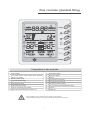
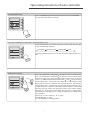
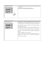
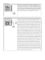
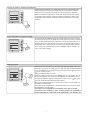
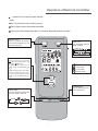
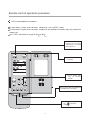
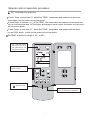
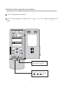
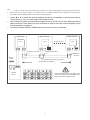
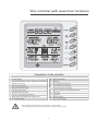
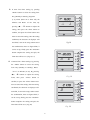
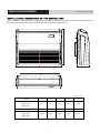
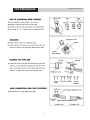
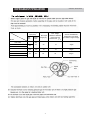
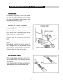
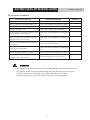
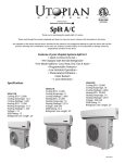
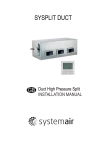
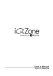
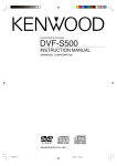
USER'S MANUAL UNI ON/OFF SERIES Floor&Ceiling units ASFU-09A, ASFU-12A, ASFU-18A, ASFU-24A ASFU-36A, ASFU-42A, ASFU-48A Thanks for your selection of SINCLAIR Air-Conditioning Unit. Before use, please read this instruction manual carefully and keep it properly to ensure correct use of this machine. Safety Considerations Component Description Operating Instructions Operating Instructions for Line Controller 1 Wire controller(standard fitting) 2 Turning On/Off Unit 3 Fan Control 3 Temperature Setting 3 Swing Function Setting 4 Sleep Function Setting 4 Operating Mode Setting 5 Timer Setting 6 Energy Saving Setting 6 Display of Outdoor Ambient Temperature 7 Power-fail Memory Function Setting 7 Debug Function 7 Failure Display 8 Operation of Remote Controller 9 Unit Function 18 Wire controller (with week timer functions) 20 Part Names and their Functions 24 Maintenance 25 Operating Guide 26 Precautions 27 Checking Before Contact The Service Man 28 Indoor Unit Installation 29 Outdoor Unit Installation Installation Instructions Profile Dimensions of Outdoor Unit for Air Duct Schematic Diagram of Unit Line Connection 32 34 35 Position and Method of Installing Wire Controller 37 Connecting Pipe Prepartion 40 Drain Piping Work 44 Routine Check after Installation 45 Test Running 46 Safety Considerations Please read this manual carefully before use and operate correctly as instructed in the manual. 1ˊ You are specially warned to note the two symbols below.: WARNING!˖A symbol indicating that improper operation might cause human death or severe injuries. A symbol indicating that improper operation might cause human injury or property damage. WARNING! z This unit shall be used in the houses, offices, restaurants, residences or similar places. z Please seek an authorized repair station for installation work. Improper installation might cause water leakage, electric shock or fire. z Please install at a place strong enough to support the weight of air conditioner unit. If not, the air conditioner unit might fall down and cause human injury or death. z To ensure proper drainage, the drainage pipe shall be correctly installed according to installation instructions. Take proper measures for heat preservation to prevent condensing. Improper installation of pipes might cause leakage and wet the articles in the room. z Do not use or store flammable, explosive, poisonous or other dangerous substances beside the air conditioner. z In case of trouble (e.g. burnt smell), please immediately cut off the main power of air conditioner unit. z Keep air flow to avoid shortage of oxygen in the room. z Never insert your finger or any objects into air outlet and inlet grill. z Never plug or unplug the power cable directly to start or stop the air-conditioning unit. z Please take constant care to check if the mounting rack is damaged after long use. z Never modify the air conditioner. Please contact the dealer or professional installation workers for repair or relocation of the air conditioner. z The appliance shall not be installed in the laundry. WARNING!: zThe installation, cleaning and maintenance work must be done by a qualified person. Do not do such work by yourself. z Before installation, please check the power supply for compliance with the ratings on nameplate. Check the power safety as well. z Before use, please check and confirm if the cables, drainage pipes and pipelines are correctly connected, hence to eliminate the risk of water leakage, refrigerant leakage, electric shock or fire. z Main power must be securely earthed to ensure effective grounding of air conditioner unit and avoid the risk of electric shock. Please do not connect the earthing cable to coal gas pipe, water pipe, lightning rod or telephone line. z Once started, the air conditioner shall not be stopped at least after 5 minutes or longer; otherwise the oil return to compressor may be affected. z Do not let the child to operate the air conditioner unit. z Do not operate the air conditioner unit with wet hands. z Please disconnect the main power before cleaning the air conditioner or replacing the air filter.(Operating by professinal) z Please disconnect the main power if to put the air conditioner unit out of use for a long period. z Please do not expose the air conditioner unit directly under corrosive environment with water or moisture. z Please do not foot on or place any goods on air conditioner unit. z After electrical installation, the air conditioner unit shall be energized for electrical leakage test. z If the supply cord is damaged, it must be replaced by the manufacturer or its service agent or a similarly qualified person in order to avoid a hazard . z An all-pole disconnection switch having a contact separation of at least 3mm in all poles should be connected in fixed wiring. z The appliance shall be installed in accordance with national wiring regulations. z The temperature of refrigerant circuit will be high, please keep the interconnection cable away from the copper tube. 1 Wire controller (standard fitting) SWING SWING TIMER Composition of wire controller 1 9 Timing display Failure status display Sleep st atus display 2 Fan speed display (Auto, High speed, Medium speed, Low speed) 10 11 Mode key 3 Defros ting st atus display 12 Se t temperature incr ease key 4 Energy saving st atus display 13 Se t temperature decr ease key 5 Se t temperature display 14 Fan speed key (fresh air setting) 6 Ambient temperature display 15 Swing key (outdoor environment temperature check) 7 Fr esh air st atus display (not supplied) 16 Timing key 8 Mode (cooling, dehumidifying,fan, heating, auto) 17 ON/OFF key • Never install the wire controller in a place where is water leakage. • Avoid bunping, throwing, tossing or frequently opening the wire controller. 2 Oper ating istructions of wire controller Turning ON/OFF unit Pr ess t he ON/OFF ke y, then the unit shall star t up. Pr ess t he ON/OFF key again, then the unit shall shut off. Fan contr ol (the figur es show the r elevant display ar eas) If the fan control key is prssed consecutively, the fan speed shall changes as per t he following sequence: Low speed Medium speed Hight speed Auto In the dehumidifying mode: The fan speed shall be automatically se t as low. Temperatur e setting Pr ess the temperature seting key ( ) to increase the set temperature; press the temperature setting key ( ) to decrease the set temperature (when pressing the keys once, the temperature shall increase or decrease by 1 °C). NOTE: key lock function: when the ( ) and ( ) key ar epressed simultaneously for 5 second, the set temperature indicating ar ea shall display “EE” and all keys response shall be shut off; press the two keys simultaneously for 5 second again, the key lock function shall be released. When the wire controller is locked by remote monitor or centralized controller, the keys of the wire controller and the signal of the remote controller ar e all locked and invalidated, and then the set temperature indicating ar ea shall display “CC”. Range of temperature setting under various modes: Heating: 16 °C ~ 30 °C Cooling: 16 °C ~ 30 °C Dehumidifying:16 °C ~ 30 °C Fan: No temperature se tting function 3 Swing function setting Press Swing button then the swing mode will be operated by the air conditioner. Repress Swing button once to stop swing mode. Note: There is no swing mode for duct type indoor unit SWING SWING TIMER Sleep function setting SWING TIMER When under the cooling or dehumidifying mode, after receiving the SLEEP order for 1 hour, the previous set temp. Tset will be risen for 1ć, and another 1ć will be risen after 2 hours that means that the temperature been risen 2ć within 2 hours. Then the unit will run according to this set temp. When under the heating mode, after receiving the SLEEP order for 1 hour, the previous set temp. Tset will be lower for 1ć, and another 1 ć will be lower after 2 hours that means that the temperature been lowered 2ć within 2 hours. Then the unit will run according to this set temp. There is no SLEEP mode under fan mode. Note˖The wired remote controller has no SLEEP mode button; if SLEEP mode is needed to be set, complete the procedure by wireless remote controller. 4 /PERATING-ODE3ETTING THIS KEY IS PRESSED CONSECUTIVELY THE OPERATING MODE SHALL CHANGE AS PERTHEFOLLOWINGSEQUENCE #OOLING$EHUMIDIFYING&AN(EATING!UTO SWING TIMER 7HENTHEUNITOPERATESUNDERh#OOLINGvMODEh#//,vSHALLBEDISPLAYED .OWTHESETTEMPERATUREMUSTBELOWERTHANTHEAMBIENTTEMPERATURE .OWIFTHESETTEMPERATUREISHIGHERTHANTHEAMBIENTTEMPERATURETHE UNIT SHALL NOT PRODUCE COOLING EFFECT BUT SHALL ONLY OPERATE UNDER &AN MODE 7HEN THE UNIT OPERATES UNDER h$EHUMIDIFYINGv MODE h$29v SHALL BE DISPLAYED.OWTHEINTERIORFANSHALLOPERATEINTHEMANNEROFLOWSPEED AIR SUPPLY WITHIN A CERTAIN RANGE OF TEMPERATURES 4HE DEHUMIDIFYING EFFECT OF THIS MODE IS BETTER THAN THAT OF THE #OOLING MODE AND SAVES MOREENERGY 7HENTHEUNITOPERATESUNDERh(EATINGvMODEh(%!4vSHALLBEDISPLAYED .OWTHESETTEMPERATUREMUSTBEHIGHERTHANTHEAMBIENTTEMPERATURE .OWIFTHESETTEMPERATUREISLOWERTHANTHEAMBIENTTEMPERATURETHE HEATINGFUNCTIONSHALLNOTBESTARTED 7HEN THE UNIT OPERATES UNDER h&ANv MODE h&!.v SHALL BE DISPLAYED 7HEN THE UNIT OPERATES UNDER h!UTOv MODE h!54/v SHALL BE DISPLAYED AND THE UNIT SHALL ADJUST ITS OPERATING MODE AUTOMATICALLY ACCORDING TO THEAMBIENTTEMPERATURE 7HENTHEUNITOPERATESUNDER(EATINGMODEANDTHEOUTDOORTEMPERA TURE IS LOW AND THE HUMIDITY IS HIGH FROST SHALL PRODUCE AT THE OUTDOOR UNIT.OWTHEHEATINGEFFICIENCYSHALLBEDECREASED7HENFROSTINGHAP PENSTHECONTROLLERSHALLAUTOMATICALLYSTARTTODEFROSTANDh$%&2/34v SHALLBEDISPLAYED .OTE#OOLINGONLYTYPEUNITDOESNOTHAVEHEATINGMODEANDWHENENER GYSAVINGISSETTHE!UTOMODESHALLBEINVALIDATED 5 Timer Setting SWING TIMER When the unit is shut off, timing start can be set; After the unit is started up, timing shutoff can be set. After the "TIMER"key is pressed, the unit enters the timing set status and the word "TIMER" flashes on the display. Now user can press ( ) or ( ) key to increase or decrease the set time. Press the "TIMER" key again and then the timing shall go into effect. Now the unit starts to count the time passed. When the unit is under timing status, you can cannel timing set by pressing the “TIMER” key.The range of set time is between 0.5 to 24 hours. %NERGY3AVING3ETTING SWING TIMER 7HENTHEUNITISSHUTOFFPRESSTHEh&!.vKEYANDTHESIMULTANEOUSLYFOR CONSECUTIVESECONDSTOACTIVATETHEENERGYSAVINGSETTINGMENU.OWh3!6%v ANDh#//,vAREDISPLAYED)NCASEITISTHEFIRSTTIMETOSETENERGYSAVINGTHEINI TIALVALUESHALLBEDISPLAYED4HELOWERLIMITOFTEMPERATURESHALLBEDISPLAYED ONTHESETTEMPERATUREANDTHETEMPERATUREVALUEUNDERSETTINGSHALLFLASH3ET THELOWERLIMITOFCOOLINGTEMPERATUREUSINGTHEKEYORTHEKEYTHELOWER LIMIT TEMPERATURE CAN BE SELECTED FROM THE RANGE BETWEEN 0RESS THE h/./&&vKEYTOCONFIRMTHESETTING!LSOUSETHEKEYORTHEKEYTOSETTHE UPPERLIMITOFTEMPERATUREANDTHETEMPERATUREVALUESHALLFLASHONTHEAMBIENT TEMPERATUREAREA/54%.6AREATHEUPPERLIMITTEMPERATURECANBESELECTED FROMTHERANGEBETWEEN0RESSTHEh/./&&vKEYTOCONFIRMTHESETTING 0LEASEPAYATTENTIONTHATTHEUPPERLIMITTEMPERATUREMUSTBEHIGHERTHANTHE SETLOWERLIMITTEMPERATURE/THERWISETHESYSTEMSHALLREGARDTHEHIGHERTEM PERATURE AS THE UPPER LIMIT TEMPERATURE AND THE LOWER ONE AS THE LOWER LIMIT TEMPERATURE 0RESS THE h-/$%v KEY TO COMPLETE THE ENERGY SAVING SETTING FOR THEMODESOFCOOLINGANDDEHUMIDIFYINGANDTURNTOTHEENERGYSAVINGSETTINGFOR THE HEATING MODE #OOLING ONLY UNIT DOES NOT HAVE THIS FUNCTION .OW THE ,#$ DISPLAYSh3!6%vANDh(%!4v!FTERSETTINGISCOMPLETEDPRESSTHEh&!.vKEY AND THE KEY SIMULTANEOUSLY FOR CONSECUTIVE SECONDS TO EXIT THE SETTING OF ENERGYSAVING!FTERTHEENERGYSAVINGSETTINGINTERFACEISACTIVATEDTHESYSTEM SHALL EXIT THE INTERFACE IF THERE IS NO ANY OPERATION WITHIN 20 seconds afTER THE LAST KEY INPUT AND THE NORMAL SHUTOFF STATUS INTERFACE SHALL BE DISPLAYED !FTER THEABOVESETTINGSARECOMPLETEDTHESYSTEMSHALLDISPLAYh3!6%v.OWTHESET TEMPERATURE SHALL NOT EXCEED THE TEMPERATURE RANGE OF THE ENERGY SAVING SET TING BEFORE &OR EXAMPLE THE LOWER COOLING LIMIT IS SET AS ²# AND THE UPPER COOLINGLIMITISSETAS²#FORTHEENERGYSAVINGTEMPERATURESETTINGIN left. SOTHECOOLINGTEMPERATURECANONLYBESELECTEDFROMTHERANGEOF²#TO²# BYUSINGTHEREMOTECONTROLLERORTHEWIRECONTROLLERLATER)FTHEUPPERLIMITTEM PERATUREISTHESAMEASTHELOWERLIMITTEMPERATURETHESYSTEMCANONLYOPERA TEATSUCHTEMPERATUREUNDERRELEVANTMODES2EMOVEOFENERGYSAVINGSETTING 4OREMOVETHEENERGYSAVINGSETTINGAFTERITTAKESINTOEFFECTYOUCANPRESSTHE h&!.vANDTHEKEYSIMULTANEOUSLYFORCONSECUTIVESECONDSWHENTHEUNITIS SHUTOFF"UTTHEVALUESETBEFOREWILLNOTBECLEAREDBUTASTHEINITIALSETTEMPE RATUREFORTHENEXTENERGYSAVINGSETTING!FTERTHEUNITISDISCONNECTEDTOPOWER SUPPLYTHEENERGYSAVINGSETTINGSHALLBESTORED4HESETTINGSTILLFUNCTIONSWHEN THEUNITISCONNECTEDTOPOWERSUPPLYAGAIN)FTHEENERGYSAVINGMODEISSETTHE SLEEPMODEANDTHEAUTOMODESHALLBEINVALIDATED 6 $ISPLAYOF/UTDOOR!MBIENT4EMPERATURE 5NDERNORMALCONDITIONSTHEh/54%.6vCOLUMNSHALLONLYDISPLAYTHE INDOORTEMPERATURE0RESSTHEh3,%%0vKEYFORCONSECUTIVESECONDS WHENTHEUNITISSHUTOFFORSTARTUPTHE,#$SHALLDISPLAYh/54%.6v !FTERTHEOUTDOORTEMPERATUREISDISPLAYEDFORSECONDSTHESYSTEM SHALLRETURNTOTHEDISPLAYINTERFACEOFINDOORTEMPERATURE.OTE)FNOT EQUIPPEDWITHANOUTDOORAMBIENTSENSORTHEUNITSHALLNOTHAVETHIS FUNCTION 0OWERFAIL-EMORY&UNCTION3ETTING 0RESSANDHOLDTHEh-/$%vKEYFORSECONDSWHENTHEUNITISSHUTOFF TOSWITCHSETVALUESSOASTODECIDEIFTHEUNITOPERATINGSTATUSORSHUTOFF STATUSSHALLBEMEMORIZEDAFTERAPOWERFAIL)FTHESETTEMPERATUREAREA DISPLAYSITMEANSTHEUNITOPERATINGSTATUSORSHUTOFFSTATUSSHALLBE MEMORIZEDAFTERAPOWERFAILMEANSTHEOPERATINGSTATUSORSHUTOFF STATUSSHALLNOTBEMEMORIZED0RESSTHEh/./&&vKEYTOSTORETHESET VALUEANDEXITTHESETTING $EBUG&UNCTION 7HENTHEUNITISSHUTOFFPRESSTHEh&!.vKEYANDTHEh3,%%0vKEYSIMUL TANEOUSLY TO ACTIVATE THE DEBUG MENU .OW THE ,#$ DISPLAYS h$%"5'v 0RESSTHEh-/$%vKEYTOSELECTSETTINGITEMANDUSETHEKEYORTHE KEYTOSETACTUALVALVE 3ETTINGOF!MBIENT4EMP3ENSOR 5NDER THE DEBUG MODE PRESS THE h-/$%v KEY SO AS TO DISPLAY hvON THESETTEMPERATUREAREAATTHELEFTOFh$%"5'v4HE/54%.6AREAAT THERIGHTOFh$%"5'vDISPLAYSSETTINGSTATUS.OWUSETHEKEYORTHE KEYTOSELECTFROMTHEFOLLOWINGTWOSETTINGS 4HE INDOOR ROOM TEMPERATURE IS MEASURED AT THE AIR INTAKE .OW THE /54%.6AREADISPLAYS 4HEINDOORROOMTEMPERATUREISMEASUREDATTHEWIRECONTROLLER.OW THE/54%.6AREADISPLAYS The indoor room temperature is measured at the wire controller when the mode is 'heating' or 'auto'. At other modes,it is measured at the air intake(Now the OUT ENV area displaus 03) ,The default is 03. 7 Failure Display When there is failure in the unit operation, “ERROR” will flash on the LCD of the wire controller and the code of failure will also be displayed. When there are multiple failures at the same time, the codes of failures will be displayed one after one on the wire controller. The first digit of the code denotes the system number. When there is only one system, the system number is not displayed. The last two digits denote the detailed failure code. For example, the code in left means low pressure protection of compressor. SWING TIMER The Codes of Failure Definitions are as Follows: Fault Fault code Fault code E0 Pump Failure Compressor High Pressure E1 Protection E2 Indoor Frost-Proof Protection Compressor Low Pressure E3 Protection Compressor Exhaust High E4 Temperature Protection Compressor Overheat E5 Fault F0 Failure of Indoor Room Sensor at Air Intake F1 Failure of Evaporator Temp. Sensor F2 Failure of Condenser Temp. Sensor F3 Failure of Outdoor Ambient Sensor F4 Failure of Exhaust Temp. Sensor F5 Failure of Indoor Room Sensor at Wire Controller E6 E8 Communications Failure Indoor Fan Protection EE Keys are locked (not failure) E9 Full Water Protection CC The unit is remotely monitored or controlled by centralized controller and the wire controller’s functions are invalidated (not failure) FF Connected control communications Failure E5 Material Malfunction Will Be Showed By The Indicator Light On The Mother Board Of Outside Unit 8 /PERATIONOF2EMOTE#ONTROLLER Name and F unction-R emote Control Note: B e sure that ther e are no obstr uctions. Don’ t drop or throw ther emote controller . Don’ t place the r emote contr oller in a location exposed to dir ect sunlight. SW I NG button W hen it is pressed, the louvers start to rotate automatically and stop when repressed. FA N button Press this button to change the fan speed of: T E M P.button T E M P. increases 1 by pressing button once,and decreases 1 by pressing button once. A t C OOL mode operation, S E T T E MP. can be selected from 16 to 30 . At DRY mode operation, SE T T E MP. can be selected from 16 to 30 . A t H E AT mode operati on, S E T T E MP. can be selected from 16 to 30 . COOL mode DRY mode FAN mode HE AT mode ON/OFF button Press this button to turn on or turn off the unit. M ODE button Press this button to change the operation mode in order of A UTO ON/OFF 9 Remote control operation procedure Name and F unction-R emote Control. (Remove the cover ) Note: This type of r emote contr oller is a k ind of new cur rent controller. Some buttons of the controller which ar e not available to this air conditioner will not be descr ibed below. L iquid crystal displayer I t shows all set contents. SL E E P button Press this button to set SL E E P operation. T I M E R OF F button A t operating, press T I ME R OFF button, set OFF T I ME in range of 0 to 24 hour to stop the unit automatically. ON/OFF T I M E R ON button A t stopping, press T I M E R ON button, set ON T IME in range of 0 to 24 hour to start the unit automatically. 0 Remote contr ol operation procedure C OOL mode oper ation pr ocedure A ccor ding to difference between room temp. and set temp., microcomputer can control cooling on or not. I f room temp. is higher than set temp., compr essor r uns at C OOL mode. I f room temp. is lower than set temp., compr essor stops and only indoor fan motor r uns. Set T E M P. should be in r ange of 16 to 30 4.Press FA N button, set fan speed. 3.Press SW I NG button, the louvers start to rotate automatically, and stop when repress. 5.Press T E M P. button, set sui tabl e T E MP. 2.Press M ODE button, set operation mode. ON/OFF 1.Plug in, press ON/OFF button,then air conditioner is turned on. 1 Remote control operation procedure H EAT mode operation pr ocedur e I f room temp. is lower than set temp., compressor r uns at H EAT mode; I f r oom temp. is higher than set temp., compressor and outdoor fan motor stop, only indoor fan motor runs. Set T E M P. should be in r ange of 16 to 30 3.Press SW I NG button, the louvers start to rotate automatically, and stop when repress it. 4.Press FA N button, set fan speed. 5.Press T E M P. button, set suitable T E MP. 1.Plug in, press ON/OFF button,then air conditioner is turned on. ON/OFF 2.Press M ODE button, set operation mode. 2 Remote contr ol operation procedure DR Y mode oper ation procedure If room Temp. is more than 2℃ below Set TEMP., compressor and outdoor unit fan motor stop, indoor unit fan motor runs as low speed. If room Temp. is between ±2℃ of Set TEMP., the compressor and outdoor unit fan motor will run for 6 minutes and stop for 4 minutes, and always in such a cycle, the indoor unit fan motor will run at low speed. If room Temp. is more than 2℃ above Set TEMP., compressor and outdoor unit fan motor run as COOL mode , indoor unit fan motor runs at low speed. Set TEMP. should be in range of 16℃ to 30℃ . 3.Press SW I NG button, the louvers start to rotate automatically, and stop when repress it. 4.Press T E M P.button,set suitable T E M P. 2.Press M ODE button,set operation mode. ON/OFF 1.Plug in,press ON/OFF button, then air conditioner is turned on. 3 Remote control operation pr ocedure A UT O mode operation pr ocedure A t A UT O mode operation, standard T E M P. is 25 mode. for C O O L mode and 20 ON/OFF 1.Plug in,Press ON/OFF button, then air conditioner is turned on. 2.According to room temp.,microcomputer can automatically set operation mode,so as for best effect. 4 for H EAT Remote contr ol operation procedure T I M E R operation procedure A t stopping,press T IME R ON button, set ON T I M E in range of 0 to 24 hour to start the unit automatically. ON/OFF A t operating,press T I M E R OF F button.set OF F T I M E in range of 0 to 24 hour to stop the unit automatically. 5 Remote control operation procedure SL E E P mode operation procedure W hen the unit is cooling or dr ying, if SL E E P operation is set, T E M P. would incr ease 1 hour and 2 in 2 hour s. Indoor fan motor r uns at low speed. W hen the unit is heating , if SL E E P oper ation is set, T E M P. would decr ease 1 2 in 2 hour s. I ndoor fan motor r uns at low speed. in 1 in 1 hour and R emote contr ocedure 4.Press FA N button, set fan speed. 3.Press SW I NG button, the louvers start to rotate automatically, and stop when repress. 6.SL E E P button Press it to set SL E E P operation. 5.Press T E M P. button, set sui tabl e T E MP. 2.Press M O DE button, or opset eration mode. ON/OFF 1.Plug in, press ON/OFF button,then air conditioner is turned on. 16 Remote control operation procedure H ow to insert batteries 1. R emove the cover from the back of the remote controller. 2. Insert the two batteries ( Two AAA dry - cell batteries ) and press button A CL . 3. R e - attach the cover. Don’ t confuse the new and wor n or different batter ies. R emove batter ies when not in use for a long time. T he r emote contr ol signal can be received at a distance of up to about 10m. 2 Insert the A A A dry-cell batteries 1 R emove the cover 3 R e - attach the cover. 17 R emote contr ol oper ation pr ocedur e 1 Note: U nit Function • 7DP - Seven days programmer (Accessory not supplied) #ENTRALIZED #ONTROL AND 7EEK 4IMER &UNCTIONS 4HE CENTRALIZED CONTROL LERANDTHEWEEKLYTIMERAREINTEGRA TED IN THE SAME WIRE CONTROLLER 4HE SYSTEMHASBOTHTHECENTRALIZEDCON TROL AND THE WEEK TIMING FUNCTIONS 5PTOSETSOFUNITSCANBECONTROL LED SIMULTANEOUSLY BY THE CENTRALIZED CONTROLLER WEEKLY TIMER 4HE WEEKLY TIMER HAS THE FUNCTION OF INVALIDATING THELOWERUNIT4HEWEEKLYTIMINGFUN CTION IS ABLE TO REALIZED FOUR TIMING /./&& PERIODS FOR ANY UNIT EVERY DAY SO AS TO ACHIEVE FULLY AUTOMATIC OPERATION 4HIS 7%%+,9 4)-%2 ADOPTS MODE TO COMMUNICATE WITH MANUAL CONTROLOFEVERYDUCTTYPEUNITANDIT CAN CONTROL UP TO UNITS !DOPTING CORE TWISTEDPAIR WIRE THE LON GEST COMMUNICATION DISTANCE OF THIS 4)-%2 IS M !FTER CONNECTED TO POWER THE 7%%+,9 4)-%2 CAN DISPLAYALLCONNECTEDUNITSSEQUENCE OF UNIT IS DETERMINED BY CODE SWITCH OF MANUAL CONTROL OF EVERY DUCT TYPE UNIT /N AND OFF OF EVERY DUCT TYPE UNIT CAN BE DONE THROUGH THE 4IMER /N/FFOFTHIS7%%+,94)-%2AND THEBUTTONSHIELDOPERATIONOFMANUAL CONTROL CAN BE DONE THROUGH SHIELD SETTING ON 7%%+,9 4)-%2 -ODE SELECTION AND TEMPERATURE ADJUST MENTANDOTHEROPERATIONSAREDONE THROUGH THE MANUAL CONTROL AT EVERY UNIT #OMPOSITIONOFPROGRAMMERWALLWEEK 5NITDISPALY 3INGLEGROUPDISPLAY 4IMERWEEKDISPLAY 4IMERDISPLAY 4IMERSTATEDISPLAY 4IMERTIMEPERIODDISPLAY 4IMER/./&&TIMEDISPLAY 5NITONDISPLAY 9 10 11 12 13 14 15 16 17 18 Unit off display Clock display Confirm button Increase button Decrease button Cacel/delete button Single/group button Timer/time button ON/OFF button Note: 1ˊ For upper unit checks 16 lower units consecutively, there will be no more than 16 seconds delay when setting works till unit responds. 2 Please let us know your requirement before your placing the order, for this WEEKLY TIMER will only be prepared when customer orders (communication joint with WEEKLY TIMER on manual control had been prepared). Press Ʒ or ͩ to select the unit that needed to be control. It is available to control several units by Group Control (1~16), or control single unit by Single Control. 2. When selected a certain or several units by Single Control or Group Control, Timer setting and On/off setting can be set. Timer setting can set 4 on/off times in a day in one week; and on/off setting can be done by pressing on/off button. 3. Connection between WEEKLY TIMER and manual control is shown as following: 1. Week timer Manual control LCD LCD Telephone wire box Manual control 16 units in max LCD Telephone wire box Telephone wire box Power supply Twisted wire with crystal joint Longest distance 1200 m On Off Power Corresponding relation between code switch and sequence of unit (NOTE: putting code switch to ON means 0) 19 Wire controller (with week timer functions) SWING 18 DAY SEG 19 SWING TIMER Composition of wire controller 1 Timing display 10 Sleep st atus display Fan speed display (Auto, High speed, Medium speed, Low speed) 11 Mode key 2 12 Se t temperature increase key 3 Defros ting st atus display 13 Se t temperature decr ease key 4 Energy saving st atus display 14 Fan speed key (fresh air setting) 5 Se t temperature display 15 Sleep key (outdoor environment temperature check) 6 Ambient temperature display 16 Timing key 7 Fr esh air st atus display (not supplied) 17 ON/OFF key 8 Mode (cooling, dehumidifying,fan, heating, auto) 18 Timer day display 9 Failure status display 19 Timer segment display s.EVERINSTALLTHEWIRECONTROLLERINAPLACEWHEREIS WATERLEAKAGE s !VOIDBUNPINGTHROWINGTOSSINGORFREQUENTLYOPENINGTHEWIRECONTROLLER 0 • Wire controller with week timer function,No.1-No17 is the same as front • instructions of No18,No.19: Timer setting (Fig. 15, 16, 17) The timer function of this display board is invalid when connect with the timer 6 ( * of the last week, the display board will SWING be controlled by the week timer. TIMER No matter the unit is turned on or turned off, press ĀTIMERābutton enter into Timer setting, then use the “Ʒ”ǃ“ͩ” buttons to select fig 15 the time (As shown In Fig.15), the setting time (Fig.16) or cancel setting (Fig.17). Then press “Timer” Button enter into each item setting. 6(* SWING TIMER fig 16 SWING TIMER fig 17 1 If enter into timer setting, by pressing “Mode” button to select the setting item: Day (Monday to Sunday), Segment 21 (1-4), Timer (timer on or timer off), the Minutes and Hours of the time; By ' $ < 6 ( * pressing “Ʒ”ǃ“ͩ” buttons to adjust the SWING setting, then press the Timer button to TIMER confirm, and press the Timer button once more to cancel the setting; After the setting confirmed, the character on displayer will Iig 18 not blink, it can not be setup; When cancel the confirmation, there are figure blink, it can be set up, finally press the “ON/OFF” button complete the setting and quit, the 2 )) timer data will be save. (Fig.18, 19) ' $ < 6 ( * If entered into “Timer setting” by pressing the “Mode” button to select the setting item: Day (Monday to Sunday), Hours SWING TIMER ˄0~23˅or Minutes (0~59); By pressing “Ʒ”ǃ“ͩ” buttons to adjust the setting ILJ items, then press “Timer” button to confirm, or press the “Timer” button once more to cancel the setting; After the setting confirmed, the character on displayer will ' $< not blink, it can not be setup; When cancel the confirmation, there are figure blink, it SWING TIMER can be set up, finally press the “ON/OFF” button complete the setting and quit, the timer data will be save. (Fig. 20) ILJ 2 If enter into “Cancel Timer”, by pressing “Ʒ”ǃ“ͩ” buttons to select Week, then press the “Timer” button to confirm, at this time, “dd” will display; or press “Timer” button to cancel the selected day, at this time “dd” will not display. At last press “ON/OFF” button complete setting and ' $< SWING TIMER quit. (Fig.21) ILJ 3 PART NAMES AND THEIR FUNCTIONS OPERATION INSTRUCTIONS Remote Control 5HPRWH&RQWURO+ROGHU ķ ĸ Ĺ ZLULQJWHUPLQDO SRZHUFRQQHFWLRQFRUG SRZHUVXSSO\FRUG VLJQFRQQHFWLRQFRUG NOTE: ķIf the supply cord is damaged, it must be replaced by the manufacturer or its service agent or a similarly qualified person in order to avoid a hazard. ĸThe appliance shall be installed in accordance with national wiring regulations. ĹAn all-pole disconnection switch having a contact separation of at least 3mm in all poles should be connected in fixed wiring. 24 SWING time “dd” will not display. At last press TIMER “ON/OFF” button complete setting and quit. (Fig.21) MAINTENANCE OPERATION INSTRUCTIONS Before inspection and maintenance of the unit, Please turn off the unit and set the power switch to “OFF” to cut off the power supply. DURING THE OFF SEASON 1. Cut off the power supply main switch 2. Clean the air filters and other parts(Done by profession) 3. Leave the fan running for 2-3 hours to dry out the inside of the unit 25` OPERATING GUIDE OPERATION INSTRUCTIONS -XVWSURIHVVLRQDOSHRSOHFRXOGFOHDQRUUHSODFHWKHILOWHU %HIRUHRSHQJULOOWRFOHDQILOHUWKHSRZHUPXVWEHFXWRIIDQGZDLWIRUWKH IDQPRWRUVWRS 26 PRECAUTIONS OPERATION INSTRUCTIONS22 27 CHECKING BEFORE CONTACT THE SERVICE MAN PROBLEM CAUSES Check if breaker switch is still on 28 OPERATION INSTRUCTIONS Indoor Uunit Installation IINSTA LLATION INSTRUCTIONS When installing the indoor unit, you can refer the paper pattern for installation, and make sure that the drainage side must be 10mm lower than the other side in order to drain the condensation water fluently. D E B A C Unit Model ASFU-09A ASFU-12A ASFU-18A ASFU-24A ASFU-36A ASFU-42A ASFU-48A mm A B C D E 836 238 745 695 260 1300 188 1202 600 260 1590 238 1491 695 260 29 Indoor Unit InstrallationO PER SELECTION OF INSTALLATION LOCATION. Such a place where cool air can be distributed throughout the room. Such a place where is condersation water is easily drained out. INSTALLATION INSTRUCTIONS CAUTION FOR INSTALLATION WHERE AIR CONDITIONER TROUBLE IS LIKELY TO OCCUR. Where there is too much of oil. Where it is acid base area. Where there is irregular electrical supply. Such a place that can handle the weight of indoor unit. Such a place which has easy access for maintenance. Such a place where is permitting easy connection with the outdoor unit. Such a place where is 1m or more away from other electric INSTALLATION PAPER PLANK appliances such as television, audio device, etc. Avoid a location where there is heat source, high humidity or inflammable gas. Do not use the unit in the immediate surroundings of a laundry, a bath, a shower or a swimming pool. Be sure that the installation conforms to the installation dimension diagram. The space around the unit is adequate for ventilation (Refer to Fig.23) )LJ THERE ARE 2 STYLES OF INSTALLATION. CEILING TYPE FLOOR TYPE 150cm or more Each type is similar to the other as follows; Determine the mounting position on ceiling or wall 60cm or more by using paper pattern to indicate indoor frarne. Mark the pattern and pull out the paper pattern. Remove the return grill,the side panel and the hanger bracket from the indoor unit as per procedure bellow. 60cm or more 30cm or more 100cm or more Press the fixing knob of the relurn grilles, the grilles will be opened wider and then pull it out from )LJ the indoor. Remove the side panel fixing screw and pull to the front direction (arrow direction) to remove. (Refer to Fig.24) 6LGHSDQHOIL[LQJVFUHZ0 Loosen two hanger bracket setting bolts (M8) on eath side for less than 10mm. Remove two hanger bracket fixing bolts (M6) on the rear side. Detach the hanger bracker by pulling it backward (Refer to Fig.26) )LJ 30 Indoor Unit Installation INSTALLATION INSTRUCTIONS Set the suspension bolt.(Use W3/8 or M10 size suspension bolts) Adjust the distance from the unit to the ceiling slab beforehand (Refer to Fig.25) 27 28 26 26 29 30 40mm or less Fig.25 Fig.25 Fig.26 Fig.28 Fig.27 Fig.29 Fig.30 31 Outdoor Unit Installation INSTALLATION INSTRUCTIONS Fig.31 Fig.32 CAUTION 32 Outdoor Unit Inatallation INS TALLATION INS TR UCTIONS E l e ct r i c w i r i n g co n n e ct i o n 5HPRYHWKHIURQWVLGHSODWH)LJ %UHDNWKURXJKWKHKROHIRUZLUHVDQGSXWRQUXEEHUEXVK 3XOODOOZLUHVWKURXJKWKHUXEEHUEXVK &RQQHFWWKHRXWGRRUXQLWDFFRUGLQJWRWKHĀ:,5,1*',$*$0āRIRXWGRRUXQLW0DNHVXUHWRZLUHILUPO\ 7LJKWHQWKHZLUHVZLWKFODPSDQGFODVS ASGE-36A ASGE-42A ASGE-48A ASGE-09A ASGE-12A ASGE-18A ASGE-24A RU CA U TI O N W rong wiring ma y ca us e fire of electric s hock. Do not pull the wire when fixing it with wire clamp and clasp. Do not let the wire too loos e All the electrical work must be done by qualified personnel according to the local rules and this instruction. T he rated voltage and the exclusive circuit mus t be us ed. L eakage circuit-breaker mus t be installed. P lease use specified fuse. If the power s upply cord of the unit is damaged, it must be replaced by the manufacturer or its service agent or a similarly qualified person in order to avoid a hazard. An all-pole disconnection air switch which have a contact separation of at least 3mm in all pole is needed. 3 Profile Dimensions of Outdoor Unit E Profile Dimensions of Outdoor Unit D A Fig. 30 B Uni t :mm Model ASGE-09A ASGE-12A ASGE-36A ASGE-24A ASGE-42A ASGE-48A Item ASGE-18A A 848 1018 1018 950 B 320 412 412 C 540 700 840 412 1250 D 540 572 572 572 E 286 300 378 378 Fig. 31 Unit Installation Instructions Precautions on Installation of Outdoor Unit To ensure the unit in proper function, selection of installation location must be in accordance with following principles: (1) Outdoor unit shall be installed so that the air discharged by outdoor unit will not return and that sufficient space for repair shall be provided around them achine. (2) The installation site must have good ventilation,so that the outdoor unit can take in and exhaust enoughair.Ensure that there is no obstacle for the airintake and exhaust of the outdoor unit.If there is any obstacle blocking the air intake or exhaust, remove it. (3) Place of installation shall be strong enough to support the w eight of outdoor unit, and it shall be able to insulate noise and prevent vibration. Ensure that the wind and noise from the unit will not affect your neighbors. (4) Avoid direct sunshine over the unit. It is bette r to set up a sun shield as the protection. (5) Place of installation must be able to drain the rainwater and defrosting water. (6) Place of installation must ensure the machine w ill not be buried under snow or subject to the influence of rubbish or oil fog. (7) The installation site must be at a place where the air exhaust outlet does not face strong wind. 34 Schematic Diagram of Unit Line Connection INSTALLATION INSTRUCTIONS Electric wiring connection The section area of cables selected by users must not be smaller than the specifications show diagram.The signal wire between indoor and outdoor unit shall be installed in the shielded bushing, and the unshielded twisted pair cable (UTP) shall be used,the cross sectional aera of the cables must be 0.75 mm2. ASGE-09A ASGE-12A ASGE-18A ASGE-24A Outdoor Unit ASFU-09A ASFU-12A ASFU-18A ASFU-24A 1、 Power cord 3×4 mm2 (H07RN-F) 2、 Power cord 3×1.5mm2 (H05VV-F) Intdoor Unit 3、 Communication Cords ASGE-36A ASGE-42A ASGE-48A (UTP) ASFU-36A ASFU-42A ASFU-48A 1、 Power cord 5×4mm2 (H07RN-F) 2、 Power cord 3×1.5mm2 (H05VV-F) 3、 Communication Cords 35 (UTP) Schematic Diagram of Unit Line Connection ASGE-02A ASGE-12A ASGE-18A ASGE-24A ASGE-36A ASGE-42A ASG-48E All the indoor units 36 INSTALLATION INSTRUCTIONS Position and Method of Installing Wire Controller INSTALLATION INSTRUCTIONS3 Position and Method of Installing Wire Controller 1. One end of the control wire of the manual controller is connected with main board of electric box of indoor unit inside, it should be tightened by wire clamp, the other end should be connected with the manual controller (installation sketch map as shown in below). The control wire be used for the indoor unit and manual controller, which is the special communication wire, the length is 8 meters, the material be adopted for the control wire should be metallic substance. The manual controller could not be disassembled and the communication wire be used for the manual controller should not be changed by users optionally, the installation and maintenance should be carried out by the professional personnel. 2. First select an installation position. According to the size of the communication line of the wire controller, leave a recess or a embedded wire hole to bury the communication line. If the communication line between the wire controller (85 h 85 h 16) and the indoor unit is surface-mounted, use 1# metallic pipe and make matching recess in the wall (refer to Figure 41); If concealed installation is adopted, 1# metallic pipe can be used (Refer to Figure 42). No matter if surface mounting or concealed mounting is selected, it is required to drill 2 holes (in the same level) which distance shall be the same as the distance (60mm) of installation holes in the bottom plate of the wire controller. Then insert a wood plug into each hole. Fix the bottom plate of the wire controller to the wall by using the two holes. Plug the communication line onto the control panel. Lastly install the panel of the wire controller. Caution: During the installation of the bottom plate of the wire controller, pay attention to the direction of the bottom plate. The plate’s side with two notches must be at the lower position, and otherwise the panel of the wire controller cannot be correctly installed. 37 Position and Method of Installing Wire Controller INSTALLATION INSTRUCTIONS Electric box cover sketch map for indoor unit communication wire Wire clamp Control wire metallic Pipe Cable-cross loop Communication wire metallic Pipe Figure 43 Surface Mounting of Cable Figure 44 Concealed mounting of Cable No. Figure 45 Schematic Diagram of Installation Name Wall Surface Bottom Plate of Wire Controller Screw M4X10 Panel of Wire Controller Caution: The communication distance between the main board and the wire controller is 8 meters. The wire controller shall not be installed in a place where there is water drop or large amount of water vapor. 38 Position and Method of Installing Wire Controller INSTALLATION INSTRUCTIONS Caution: Before installing the electrical equipment, please pay attention to the following matters which have been specially pointed out by our designers: ˄˅ Check to see if the power supply used conforms to the rated power supply specified on the nameplate. ˄˅ The capacity of the power supply must be large enough. . ˄˅ The lines must be installed by professional personnel. An electricity leakage protection switch and an air switch with gap between electrode heads larger than 3mm shall be installed in the fixed line. 1. Connection of single wire ˄1˅ Use wire stripper to strip the insulation layer (25mm long) from the end of the single wire. ˄2˅ Remove the screw at the terminal board of the air-conditioning unit. ˄3˅ User pliers to bend the end of the single wire so that a loop matching the screw size is formed. ˄4˅ Put the screw through the loop of the single wire and fix the loop at the terminal board. 2. Connection of multiple twisted wires ˄1˅ Use wire stripper to strip the insulation layer (10mm long) from the end of the multiple twisted wires. ˄2˅ Remove the screw at the terminal board of the air-conditioning unit. ˄3˅ Use crimping pliers to connect a terminal (matching the size of the screw) at the end of the multiple twisted wires. ˄4˅ Put the screw through the terminal of the multiple twisted wires and fix the terminal at the terminal board. Warning: If the power supply flexible line or the signal line of the equipment is damaged, only use special flexible line to replace it. 1. Before connecting lines, read the voltages of the relevant parts on the nameplate. Then carry out line connection according to the schematic diagram. 2. The air-conditioning unit shall have special power supply line which shall be equipped with electricity leakage switch and air switch, so as to deal with overload conditions. 3. The air-conditioning unit must have grounding to avoid hazard owing to insulation failure. 4. All fitting lines must use crimp terminals or single wire. If multiple twisted wires are connected to terminal board, arc may arise. 5. All line connections must conform to the schematic diagram of lines. Wrong connection may cause abnormal operation or damage of the air-conditioning unit. 6. Do not let any cable contact the refrigerant pipe, the compressor and moving parts such as fan. 7. Do not change the internal line connections inside the air-conditioning unit. The manufacturer shall not be liable for any loss or abnormal operation arising from wrong line connections. Connection of Signal Line of Wire Controller 1. Open the cover of the electric box of the indoor unit. 2. Pull the signal cable of the wire controller through the rubber ring. 3. Plug the signal line of the wire controller onto the 4-bit pin socket(CN9) at the circuit board of the indoor unit. 4. Use cable fastener to bundle and fix the signal cable of the wire controller. 39 PIPE PREPARATION OPERATION INSTRUCTIONS 40 REFRIGERANT PIPING WORK Item Size of Fitting Pipe (mm) Gas Pipe Model ASFU-09A ASFU-12A ASFU-18A ASFU-24A Liquid Pipe Max. Pipe Length (m) OPERATION INSTRUCTIONS Max. Height Difference between Indoor Unit and Outdoor Unit m Amount of Additional Refrigerant to be Filled (For Extra Length of Pipe) 3/8” 1/2” 5/8” 1/4" 20 15 30g/m 3/8” 30 15 60g/m ASFU-36A ASFU-42A 3/4” 1/2” 50 30 ASFU-48A 41 120g/m AIR PURGING AND CHECK OF PIPE LEAKAGE 42 OPERATION INSTRUCTIONS LIQUID PIPE AND DRAIN PIPE 43 OPERATION INSTRUCTIONS DRAIN PIPING WORK OPERATION INSTRUCTIONS45 44 ROUTINE CHECK AFTER INSTALLATION OPERATION INSTRUCTIONS Check after installation Items to be checked Possible malfunction Has it been fixed firmly? The unit may drop,shake or emit noise. Have you done the refrigerant leakage test? It may cause insufficient refrigerating capacity. Is heat insulation sufficient? It may cause condensation and dripping. Does the unit drain well? It may cause condensation and dripping. Is the voltage in accordance with the rated voltage marked on the nameplate? It may cause electric malfunction or damage the part. Is the electrical wiring and piping connection installed correctly and securely? It may cause electric malfunction or damage the part. Has the unit been connected to a secure earth connection? It may cause electrical leakage. Is the power cord specified? It may cause electric malfunction or damage the part. Has the inlet and outlet been covered? It may cause insufficient refrigerating capacity. Has the length of connection pipes and the refrigerant charge been record? Situation The refrigerating capacity is not accurate WARNING! 1. This appliance is not intended for use by persons (including children) with reduced physical sensory or capabilities, or lack of experience and knowledge, unless they have been given supervision or instruction concerning use of the appliance by a person responsible for their safety. 2. Children should be supervised to ensure that they do not play with the appliance. 45 TEST RUNNING OPERATION INSTRUCTIONS EVALUATION OF THE PERFORMANCE Check electrical main wire's voltage. Use a thermometer to measure cool air both in and out. The difference between in-air and out-air temperature should not be less than Thermometer The unithas Auto-restart funcation, it can remember the running model before power-broken. Be sure to use the exclusive accessories list above in the installation. or it will lead to water leakage, electric shock, fire, etc. Appendix: Air conditioner nominal working condition and working range: Test condition Indoor side Outdoor side DB(℃) WB(℃) DB(℃) WB(℃) Nominal cooling 27 19 35 24 Nominal heating 20 ―― 7 6 Rated cooling 32 23 43 26 Low temp. cooling 21 15 Rated heating 27 ―― 24 18 Low temp. heating 20 ―― -7 -8 18(-7) ―― Note: 1. The design of this unit conforms to the requirements of EN14511 standard. 2. The air volume is measured at the relevant standard external static pressure. 3. Cooling (heating) capacity stated above is measured under nominal working conditions corresponding to standard external static pressure. The parameters are subject to change with the improvement of products, in which case the values on nameplate shall prevail. 4. In this table, the outdoor side DB temperature of low temp. cooling include two values, the one in the bracket is the working condition of the appliance with function of low temp. cooling . 46 This product must not be disposed together with the domestic waste. This product has to be disposed at an authorized place for recycling of electrical and electronic appliances. 66179403