1
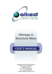
METHOD 30B – DETERMINATION OF TOTAL VAPOR PHASE MERCURY
EMISSIONS FROM COAL-FIRED COMBUSTION SOURCES USING CARBON
SORBENT TRAPS
1.0 Scope and Application
What is Method 30B?
Method 30B is a procedure for measuring total vapor phase mercury (Hg)
emissions from coal-fired combustion sources using sorbent trap sampling and an
extractive or thermal analytical technique. This method is only intended for use only
under relatively low particulate conditions (e.g., sampling after all pollution control
devices). Quality assurance and quality control requirements are included to assure that
you, the tester, collect data of known and acceptable quality for each testing program.
This method does not completely describe all equipment, supplies, and sampling and
analytical procedures you will need, but instead refers to other test methods for some of
the details. Therefore, to obtain reliable results, you should also have a thorough
knowledge of these additional methods which are found in Appendices A-1 and A-3 to
this part:
(a)
Method 1—Sample and Velocity Traverses for Stationary Sources.
(b)
Method 4—Determination of Moisture Content in Stack Gases.
(c)
Method 5—Determination of Particulate Matter Emissions from
Stationary Sources
1.1 Analytes. What does this method determine? This method is designed to
measure the mass concentration of total vapor phase Hg in flue gas, including elemental
Hg (Hgo) and oxidized forms of Hg (Hg+2), in micrograms per dry standard cubic meter
1
(µg/dscm).
Analyte
CAS No.
Elemental Hg (Hgo)
7439-97-6
Oxidized Hg (Hg+2)
-----
Analytical Range and Sensitivity
Typically 0.1 µg/dscm to > 50 µg/dscm
(Same)
1.2 Applicability. When is this method required? Method 30B is a reference
method for relative accuracy test audits (RATAs) of vapor phase Hg CEMS and sorbent
trap monitoring systems installed at coal-fired boilers and is also appropriate for Hg
emissions testing at such boilers. It is intended for use only under relatively low
particulate conditions (i.e., sampling after all pollution control devices); in cases where
significant amounts of particle-bound Hg may be present, an isokinetic sampling method
for Hg should be used. Method 30B may also be specified by New Source Performance
Standards (NSPS), National Emission Standards for Hazardous Air Pollutants
(NESHAP), emissions trading programs, State Implementation Plans (SIPs), and
operating permits that require measurement of Hg concentrations in stationary source
emissions, either to determine compliance with an applicable emission standard or limit,
or to conduct RATAs of Hg CEMS and sorbent trap monitoring systems.
1.3 Data Quality Objectives (DQO). How good must my collected data be?
Method 30B has been designed to provide data of high and known quality for Hg
emissions testing and for RATA testing of Hg monitoring systems, including CEMS and
sorbent trap monitors. In these and other applications, the principal objective is to ensure
the accuracy of the data at the actual emissions levels and in the actual emissions matrix
encountered. To meet this objective, NIST-traceable calibration standards must be used
2
and method performance tests are required.
2.0 Summary of Method
Known volumes of flue gas are extracted from a stack or duct through paired, instack sorbent media traps at an appropriate flow rate. Collection of mercury on the
sorbent media in the stack mitigates potential loss of mercury during transport through a
probe/sample line. For each test run, paired train sampling is required to determine
measurement precision and verify acceptability of the measured emissions data. A field
recovery test which assesses recovery of an elemental Hg spike to determine
measurement bias is also used to verify data acceptability. The sorbent traps are
recovered from the sampling system, prepared for analysis as needed, and analyzed by
any suitable determinative technique that can meet the performance criteria.
3.0
Definitions
3.1 Analytical System is the combined equipment and apparatus used to perform
sample analyses. This includes any associated sample preparation apparatus e.g.,
digestion equipment, spiking systems, reduction devices, etc., as well as analytical
instrumentation such as UV AA and UV AF cold vapor analyzers.
3.2 Calibration Standards are the Hg containing solutions prepared from NIST
traceable standards and are used to directly calibrate analytical systems.
3.3 Independent Calibration Standard is a NIST traceable standard obtained from
a source or supplier independent of that for the calibration standards and is used to
confirm the integrity of the calibration standards used.
3.4 Method Detection Limit (MDL) is the lowest mass of Hg greater than zero
that can be estimated and reported by your candidate analytical technique. The MDL is
3
statistically derived from replicate low level measurements near your analytical
instrument’s detection level.
3.5
NIST means the National Institute of Standards and Technology, located in
Gaithersburg, Maryland.
3.6 Run means a series of gas samples taken successively from the stack or duct.
A test normally consists of a specific number of runs.
3.7 Sorbent Trap means a cartridge or sleeve containing a sorbent media
(typically activated carbon treated with iodine or some other halogen) with multiple
sections separated by an inert material such as glass wool. These sorbent traps are
optimized for the quantitative capture of elemental and oxidized forms of Hg and can be
analyzed by multiple techniques.
3.8 Test refers to the series of runs required by the applicable regulation.
3.9 Thermal Analysis means an analytical technique where the contents of the
sorbent traps are analyzed using a thermal technique (desorption or combustion) to
release the captured Hg in a detectable form for quantification.
3.10 Wet Analysis means an analytical technique where the contents of the
sorbent tube are first leached or digested to quantitatively transfer the captured Hg to
liquid solution for subsequent analysis.
4.0
Interferences
Interferences may result from the sorbent trap material used as well as from the
measurement environment itself. The iodine present on some sorbent traps may impart a
negative measurement bias. High levels of sulfur trioxide (SO3) are also suspected to
compromise the performance of sorbent trap Hg capture. These, and other, potential
4
interferences are assessed by performing the analytical matrix interference, Hg0 and
HgCl2 analytical bias and field recovery tests.
5.0 Safety
What safety measures should I consider when using this method? This
method may require you to work with hazardous materials and in hazardous conditions.
You are encouraged to establish safety procedures before using the method. Among
other precautions, you should become familiar with the safety recommendations in the
gas analyzer user’s manual. Occupational Safety and Health Administration (OSHA)
regulations concerning use of compressed gas cylinders and noxious gases may apply.
5.1 Site Hazards. Prior to applying these procedures/specifications in the field,
the potential hazards at the test site should be considered; advance coordination with the
site is critical to understand the conditions and applicable safety policies. At a minimum,
portions of the sampling system will be hot, requiring appropriate gloves, long sleeves,
and caution in handling this equipment.
5.2 Laboratory Safety. Policies should be in place to minimize risk of chemical
exposure and to properly handle waste disposal in the laboratory. Personnel shall wear
appropriate laboratory attire according to a Chemical Hygiene Plan established by the
laboratory.
5.3 Reagent Toxicity/Carcinogenicity. The toxicity and carcinogenicity of any
reagents used must be considered. Depending upon the sampling and analytical
technologies selected, this measurement may involve hazardous materials, operations,
and equipment and this method does not address all of the safety problems associated
with implementing this approach. It is the responsibility of the user to establish
5
appropriate safety and health practices and determine the applicable regulatory
limitations prior to performance. Any chemical should be regarded as a potential health
hazard and exposure to these compounds should be minimized. Chemists should refer to
the Material Safety Data Sheet (MSDS) for each chemical used.
5.4 Waste Disposal. Any wastes generated by this procedure must be disposed of
according to a hazardous materials management plan that details and tracks various waste
streams and disposal procedures.
6.0 Equipment and Supplies
The following list is presented as an example of key equipment and supplies
likely required to measure vapor-phase Hg using a sorbent trap sampling system. It is
recognized that additional equipment and supplies may be needed. Collection of paired
samples is required.
6.1 Sorbent Trap Sampling System. A typical sorbent trap
sampling system is shown in Figure 30B-1 in Section 17.0. The sorbent trap sampling
system shall include the following components:
6.1.1 Sorbent Traps. The sorbent media used to collect Hg must be configured in
a trap with at least two distinct segments or sections, connected in series, that are
amenable to separate analyses. Section 1 is designated for primary capture of gaseous
Hg. Section 2 is designated as a backup section for determination of vapor phase Hg
breakthrough. Each sorbent trap must be inscribed or otherwise permanently marked
with a unique identification number, for tracking purposes. The sorbent media may be
any collection material (e.g., carbon, chemically-treated filter, etc.) capable of
quantitatively capturing and recovering for subsequent analysis, all gaseous forms of Hg
in the emissions from the intended application. Selection of the sorbent media shall be
6
based on the material’s ability to achieve the performance criteria contained in this
method as well as the sorbent’s vapor phase Hg capture efficiency for the emissions
matrix and the expected sampling duration at the test site. The sorbent media must be
obtained from a source that can demonstrate their quality assurance and quality control
(see Section 7.2). The paired sorbent traps are supported on a probe (or probes) and
inserted directly into the flue gas stream.
6.1.2 Sampling Probe Assembly. Each probe assembly shall have a leak-free
attachment to the sorbent trap(s). Each sorbent trap must be mounted at the entrance of
or within the probe such that the gas sampled enters the trap directly. Each probe/sorbent
trap assembly must be heated to a temperature sufficient to prevent liquid condensation in
the sorbent trap(s). Auxiliary heating is required only where the stack temperature is too
low to prevent condensation. Use a calibrated thermocouple to monitor the stack
temperature. A single probe capable of operating the paired sorbent traps may be used.
Alternatively, individual probe/sorbent trap assemblies may be used, provided that the
individual sorbent traps are co-located to ensure representative Hg monitoring.
6.1.3 Moisture Removal Device. A moisture removal device or system shall be
used to remove water vapor from the gas stream prior to entering dry gas flow metering
devices.
6.1.4 Vacuum Pump. Use a leak-tight, vacuum pump capable of operating within
the system’s flow range.
6.1.5 Gas Flow Meter. A gas flow meter (such as a dry gas meter, thermal mass
flow meter, or other suitable measurement device) shall be used to determine the total
sample volume on a dry basis, in units of standard cubic meters. The meter must be
7
sufficiently accurate to measure the total sample volume to within 2 percent and must be
calibrated at selected flow rates across the range of sample flow rates at which the
sampling train will be operated. The gas flow meter shall be equipped with any
necessary auxiliary measurement devices (e.g., temperature sensors, pressure
measurement devices) needed to correct the sample volume to standard conditions.
6.1.6 Sample Flow Rate Meter and Controller. Use a flow rate indicator and
controller for maintaining necessary sampling flow rates.
6.1.7 Temperature Sensor. Same as Section 6.1.1.7 of Method 5 in Appendix A3 to this part.
6.1.8 Barometer. Same as Section 6.1.2 of Method 5 in Appendix A-3 to this
part.
6.1.9 Data Logger (optional). Device for recording associated and necessary
ancillary information (e.g., temperatures, pressures, flow, time, etc.).
6.2 Gaseous Hg0 Sorbent Trap Spiking System. A known mass of gaseous Hg0
must be either present on or spiked onto the first section of sorbent traps in order to
perform the Hg0 and HgCl2 analytical bias test and the field recovery study. Any
approach capable of quantitatively delivering known masses of Hg0 onto sorbent traps is
acceptable. Several spiking technologies or devices are available to meet this objective.
Their practicality is a function of Hg mass spike levels. For low levels, NIST-certified or
NIST-traceable gas generators or tanks may be suitable. An alternative system, capable
of delivering almost any mass required, makes use of NIST-certified or NIST-traceable
Hg salt solutions (e.g., HgCl2, Hg(NO3)2). With this system, an aliquot of known volume
and concentration is added to a reaction vessel containing a reducing agent (e.g., stannous
8
chloride); the Hg salt solution is reduced to Hg0 and purged onto the sorbent trap using an
impinger sparging system. When available, information on example spiking systems will
be posted at http://www.epa.gov/ttn/emc.
6.3 Sample Analysis Equipment. Any analytical system capable of quantitatively
recovering and quantifying total Hg from the sorbent media selected is acceptable
provided that the analysis can meet the performance criteria described in this method.
Example recovery techniques include acid leaching, digestion, and thermal
desorption/direct combustion. Example analytical techniques include, but are not limited
to, ultraviolet atomic fluorescence (UV AF), ultraviolet atomic absorption (UV AA) with
and without gold trapping, and X-ray fluorescence (XRF) analysis.
6.3 Moisture Measurement System. If correction of the measured Hg emissions
for moisture is required (see Section 8.3.3.7), either Method 4 in Appendix A-3 to this
part or other moisture measurement methods approved by the Administrator will be
needed to measure stack gas moisture content.
7.0 Reagents and Standards
7.1 Reagents and Standards. Only NIST-certified or NIST-traceable calibration
standards, standard reference materials, and reagents shall be used for the tests and
procedures required by this method.
7.2 Sorbent Trap Media. The sorbent trap media shall be prepared such that the
material used for testing is of known and acceptable quality. Sorbent supplier quality
assurance/quality control measures to ensure appropriate and consistent performance
such as sorptive capacity, uniformity of preparation treatments, and background levels
shall be considered.
9
8.0 Sample Collection and Handling
This section presents the sample collection and handling procedures along with
the pretest and on-site performance tests required by this method. Since you may choose
different options to comply with certain performance criteria, each test report must
identify the specific options selected and document the results with respect to the
performance criteria of this method.
8.1 Sample Point Selection. What sampling site and sampling points do I
select? Same as Section 8.1 of Method 30A of this appendix.
8.2 Measurement System Performance Tests. What performance criteria must
my measurement system meet? The following laboratory and field procedures and
associated criteria of this section are designed to ensure (1) selection of a sorbent and
analytical technique combination capable of quantitative collection and analysis of
gaseous Hg, (2) collection of an adequate amount of Hg on each sorbent trap during field
tests, and (3) adequate performance of the method for each test program: The primary
objectives of these performance tests are to characterize and verify the performance of
your intended analytical system and associated sampling and analytical procedures, and
to define the minimum amount of Hg (as the sample collection target) that can be
quantified reliably.
(a) Analytical Matrix Interference Test;
(b) Determination of Minimum Sample Mass;
(c) Hg0 and HgCl2 Analytical Bias Test;
(d) Determination of Nominal Sample Volume;
(e) Field Recovery Test.
10
8.2.1 Analytical Matrix Interference Test and Minimum Sample Dilution.
(a) The analytical matrix interference test is a laboratory procedure. It is required
only if you elect to use a liquid digestion analytical approach and needs to be performed
only once for each sorbent material used. The purpose of the test is to verify the presence
or absence of known and potential analytical matrix interferences, including the potential
negative bias associated with iodine common to many sorbent trap materials. The
analytical matrix interference test determines the minimum dilution (if any) necessary to
mitigate matrix effects on the sample digestate solutions.
(b) The result of the analytical matrix interference test, i.e., the minimum sample
dilution required (if any) for all sample analyses, is used to establish the minimum
sample mass needed for the Hg0 and HgCl2 analytical bias test and to determine the
nominal sample volume for a test run. The analytical matrix interference test is sorbent
material-specific and shall be performed for each sorbent material you intend to use for
field sampling and analysis. The test shall be performed using a mass of sorbent material
comparable to the sorbent mass typically used in the first section of the trap for sampling.
Similar sorbent materials from different sources of supply are considered to be different
materials and must be tested individually. You must conduct the analytical matrix
interference test for each sorbent material prior to the analysis of field samples.
8.2.1.1 Analytical Matrix Interference Test Procedures. Digest and prepare for
analysis a representative mass of sorbent material (unsampled) according to your
intended laboratory techniques for field samples. Analyze the digestate according to your
intended analytical conditions at the least diluted level you intend to use for sample
analysis (e.g., undiluted, 1 in 10 dilution, etc.). Determine the Hg concentration of the
11
undiluted digestate solution. Prepare a series of solutions with a fixed final volume
containing graduated aliquots of the sample digestate and, a fixed aliquot of a calibration
standard (with the balance being Hg-free reagent or H20) to establish solutions of varied
digestate dilution ratio (e.g., 1:2, 1:5, 1:10, 1:100, etc.---see example in Section 8.2.1.3,
below). One of these solutions should contain only the aliquot of the calibration standard
in Hg-free reagent or H20. This will result in a series of solutions where the amount of
Hg is held relatively constant and only the volume of digestate diluted is varied. Analyze
each of these solutions following intended sample analytical procedures and conditions,
determining the concentration for each solution.
8.2.1.2 Analytical Matrix Interference Test Acceptance Criteria. Compare the
measured concentration of each solution containing digestate to the measured
concentration of the digestate-free solution. The lowest dilution ratio of any solution
having a Hg concentration within ±5 percent of the digestate-free solution is the
minimum dilution ratio required for analysis of all samples. If you desire to measure the
digestate without dilution, the + 5 percent criterion must be met at a dilution ratio of at
least 9:10 (i.e., ≥ 90% digestate).
8.2.1.3 Example Analytical Matrix Interference Test. An example analytical
matrix interference test is presented below. Additional information on the conduct of the
analytical matrix interference test will be posted at http://www.epa.gov/ttn/emc.
Determine the most sensitive working range for the analyzer to be used. This will be a
narrow range of concentrations. Digest and prepare for analysis a representative mass of
sorbent material (unsampled) according to your intended laboratory techniques for
sample preparation and analysis. Prepare a calibration curve for the most sensitive
12
analytical region, e.g., 0.0, 0.5, 1.0, 3.0, 5.0, 10 ppb. Using the highest calibration
standard, e.g.., 10.0 ppb, prepare a series of solutions by adding successively smaller
increments of the digestate to a fixed volume of the calibration standard and bringing
each solution to a final fixed volume with mercury-free deionized water (diH2O). To 2.0
ml of the calibration standard add 18.0, 10.0, 4.0, 2.0, 1.0, 0.2, and 0.0 ml of the
digestate. Bring the final volume of each solution to a total volume of 20 ml by adding
0.0, 8.0, 14.0, 16.0, 17.0, 17.8, and 18.0 ml of diH2O. This will yield solutions with
dilution ratios of 9:10, 1:2, 1:5, 1:10, 1:20, 1:100, and 0:10, respectively. Determine the
Hg concentration of each solution. The dilution ratio of any solution having a
concentration that is within ±5 percent of the concentration of the solution containing 0.0
ml of digestate is an acceptable dilution ratio for analyzing field samples. If more than
one solution meets this criterion, the one with the lowest dilution ratio is the minimum
dilution required for analysis of field samples. If the 9:10 dilution meets this criterion,
then no sample dilution is required.
8.2.2 Determination of Minimum Sample Mass. The minimum mass of Hg that
must be collected per sample must be determined. This information is necessary in order
to effectively perform the Hg0 and HgCl2 Analytical Bias Test, to estimate target sample
volumes/sample times for test runs, and to ensure the quality of the measurements. The
determination of minimum sample mass is a direct function of analytical technique,
measurement sensitivity, dilutions, etc. This determination is required for all analytical
techniques. Based on the analytical approach you employ, you should determine the
most sensitive calibration range. Based on a calibration point within that range, you must
consider all sample treatments (e.g., dilutions) to determine the mass of sample that needs
13
to be collected to ensure that all sample analyses fall within your calibration curve.
8.2.2.1 Determination of Minimum Calibration Concentration or Mass. Based on
your instrument’s sensitivity and linearity, determine the calibration concentrations or
masses that make up a representative low level calibration range. Verify that you are able
to meet the multipoint calibration performance criteria in section 11.0 of this method.
Select a calibration concentration or mass that is no less than 2 times the lowest
concentration or mass in your calibration curve. The lowest point in your calibration
curve must be at least 5, and preferably10, times the Method Detection Limit (MDL),
which is the minimum amount of the analyte that can be detected and reported. The
MDL must be determined at least once for the analytical system using an MDL study
such as that found in section 17.0 of the proposed amendments to EPA Method 301 (69
FR 76642, 12/22/2004).
Note to Section 8.2.2.1: While it might be desirable to base the minimum
calibration concentration or mass on the lowest point in the calibration curve, selecting a
higher concentration or mass is necessary to ensure that all analyses of the field samples
will fall within the calibration curve. Therefore, it is strongly recommended that you
select a minimum calibration concentration or mass that is sufficiently above the lowest
point of the calibration curve (see examples in sections 8.2.2.2.1 and 8.2.2.2.2 below).
8.2.2.2 Determination of Minimum Sample Mass. Based on your minimum
calibration concentration or mass and other sample treatments including, but not limited
to, final digestate volume and minimum sample dilution, determine the minimum sample
mass. Consideration should also be given to the Hg levels expected to be measured in
Section 2 of the sorbent traps and to the breakthrough criteria presented in Table 9-1.
14
8.2.2.2.1 Example Determination of Minimum Sample Mass for Thermal
Desorption Analysis. A thermal analysis system has been calibrated at five Hg mass
levels: 10 ng, 20 ng, 50 ng, 100 ng, 200 ng, and shown to meet the calibration
performance criteria in this method. Based on 2 times the lowest point in the calibration
curve, 20 ng is selected as the minimum calibration mass. Because the entire sample is
analyzed and there are no dilutions involved, the minimum sample mass is also 20 ng.
Note: In this example, if the typical background (blank) Hg levels in section 2 were
relatively high (e.g., 3 to 5 ng), a sample mass of 20 ng might not have been sufficient to
ensure that the breakthrough criteria in Table 9-1 would be met, thereby necessitating the
use of a higher point on the calibration curve (e.g., 50 ng) as the minimum calibration and
sample mass.
8.2.2.2.2 Example Determination of Minimum Sample Mass for Acid
Leachate/Digestate Analysis. A cold vapor analysis system has been calibrated at four
Hg concentration levels: 2 ng/L, 5 ng, 10 ng/L, 20 ng/L, and shown to meet the
calibration performance criteria in this method. Based on 2 times the lowest point in the
calibration curve, 4 ng/L was selected as the minimum calibration concentration. The
final sample volume of a digestate is nominally 50 ml (0.05 L) and the minimum dilution
necessary was determined to be 1:100 by the Analytical Matrix Interference Test of
Section 8.2.1. The following calculation would be used to determine the minimum
sample mass.
Minimum sample mass = (4 ng/L) X (0.05 L) X (100) = 20 ng
Note: In this example, if the typical background (blank) Hg levels in section 2 were
relatively high (e.g., 3 to 5 ng), a sample mass of 20 ng might not have been sufficient to
15
ensure that the breakthrough criterion in Table 9-1 would be met, thereby necessitating
the use of a higher point on the calibration curve (e.g., 10 ng/L) as the minimum
calibration concentration.
8.2.3 Hg0 and HgCl2 Analytical Bias Test. Before analyzing any field samples,
the laboratory must demonstrate the ability to recover and accurately quantify Hg0 and
HgCl2 from the chosen sorbent media by performing the following analytical bias test for
sorbent traps spiked with Hg0 and HgCl2. The analytical bias test is performed at a
minimum of two distinct sorbent trap Hg loadings that will: (1) represent the lower and
upper bound of sample Hg loadings for application of the analytical technique to the field
samples, and (2) be used for data validation.
8.2.3.1 Hg0 and HgCl2 Analytical Bias Test Procedures. Determine the lower
and upper bound mass loadings. The minimum sample mass established in Section
8.2.2.2 can be used for the lower bound Hg mass loading although lower Hg loading
levels are acceptable. The upper bound Hg loading level should be an estimate of the
greatest mass loading that may result as a function of stack concentration and volume
sampled. As previously noted, this test defines the bounds that actual field samples must
be within in order to be valid.
8.2.3.1.1 Hg0 Analytical Bias Test. Analyze the front section of three sorbent
traps containing Hg0 at the lower bound mass loading level and the front section of three
sorbent traps containing Hg0 at the upper bound mass loading level. In other words,
analyze each mass loading level in triplicate. You may refer to Section 6.2 for spiking
guidance. Prepare and analyze each spiked trap, using the same techniques that will be
used to prepare and analyze the field samples. The average recovery for the three traps at
16
each mass loading level must be between 90 and 110 percent. If multiple types of
sorbent media are to be analyzed, a separate analytical bias test is required for each
sorbent material.
8.2.3.1.2 HgCl2 Analytical Bias Test. Analyze the front section of three sorbent
traps containing HgCl2 at the lower bound mass loading level and the front section of
three traps containing Hg Cl2 at the upper bound mass loading level. HgCl2 can be
spiked as a gas, or as a liquid solution containing HgCl2. However the liquid volume
spiked must be <100 µL. Prepare and analyze each spiked trap, using the techniques that
will be used to prepare and analyze the field samples. The average recovery for three
traps at each spike concentration must be between 90 and 110 percent. Again, if multiple
types of sorbent media are to be analyzed, a separate analytical bias test is required for
each sorbent material.
8.2.4 Determination of Target Sample Volume. The target sample volume is an
estimate of the sample volume needed to ensure that valid emissions data are collected
(i.e., that sample mass Hg loadings fall within the analytical calibration curve and are
within the upper and lower bounds set by the analytical bias tests). The target sample
volume and minimum sample mass can also be determined by performing a diagnostic
test run prior to initiation of formal testing.
Example: If the minimum sample mass is 50 ng and the concentration of mercury in the
stack gas is estimated to be 2 µg/m3 (ng/L) then the following calculation would be used
to determine the target sample volume:
Target Sample Volume = (50 ng)/(2 ng/L) = 25 L
Note: For the purposes of relative accuracy testing of Hg monitoring systems under part
17
75 of this chapter and Performance Specification 12A in appendix B to this part, when
the stack gas Hg concentration is expected to be very low (<0.5 :g/dscm) you may
estimate the Hg concentration at 0.5 :g/dscm .
8.2.5 Determination of Sample Run Time. Sample run time will be a function of
minimum sample mass (see Section 8.2.2), target sample volume and nominal equipment
sample flow rate. The minimum sample run time for conducting relative accuracy test
audits of Hg monitoring systems is 30 minutes and for emissions testing to characterize
an emission source is 1 hour. The target sample run time can be calculated using the
following example.
Example: If the target sample volume has been determined to be 25 L, then the following
formula would be used to determine the sampling time necessary to acquire 25 L of gas
when sampling at a rate of 0.4 L/min.
Sampling time (min) = 25 L / 0.4 L/min = 63 minutes
8.2.6 Field Recovery Test. The field recovery test provides a test programspecific verification of the performance of the combined sampling and analytical
approach. Three sets of paired samples, one of each pair which is spiked with a known
level of Hg, are collected and analyzed and the average recovery of the spiked samples is
used to verify performance of the measurement system under field conditions during that
test program. The conduct of this test requires an estimate or confirmation of the stack
Hg concentrations at the time of testing.
8.2.6.1 Calculation of Pre-sampling Spiking Level. Determine the sorbent trap
spiking level for the field recovery test using estimates of the stack Hg concentration, the
target sample flow rate, and the planned sample duration. First, determine the Hg mass
18
expected to be collected in section 1 of the sorbent trap. The pre-sampling spike must be
within 50 to150 percent of this expected mass.
Example calculation: For an expected stack Hg concentration of 5 ug/m3 (ng/L) a target
sample rate of 0.40 liters/min, and a sample duration of 1 hour:
(0.40 L/min)*(60 min)*(5ng/L) = 120 ng
A Hg spike of 60 to 180 ng (50-150% of 120 ng) would be appropriate.
8.2.6.2 Procedures. Set up two identical sampling trains. One of the sampling
trains shall be designated the spiked train and the other the unspiked train. Spike Hg0
onto the front section of the sorbent trap in the spiked train before sampling. The mass of
Hg spiked shall be 50 to 150 percent of the mass expected to be collected with the
unspiked train. Sample the stack gas with the two trains simultaneously using the same
procedures as for the field samples (see Section 8.3). The total sample volume must be
within + 20 percent of the target sample volume for the field sample test runs. Analyze
the sorbent traps from the two trains utilizing the same analytical procedures and
instrumentation as for the field samples (see Section 11.0). Determine the fraction of
spiked Hg recovered (R) using the equations in Section 12.7. Repeat this procedure for a
total of three runs. Report the individual R values in the test report; the average of the
three R values must be between 85 and 115 percent.
Note to section 8.2.6.2: It is acceptable to perform the field recovery test
concurrent with actual test runs (e.g., through the use of a quad probe). It is also
acceptable to use the field recovery test runs as test runs for emissions testing or for the
RATA of a Hg monitoring system under part 75 of this chapter and Performance
Specification 12A in appendix B to this part, if certain conditions are met. To determine
19
whether a particular field recovery test run may be used as a RATA run,, subtract the
mass of the Hg0 spike from the total Hg mass collected in sections 1 and 2 of the spiked
trap. The difference represents the mass of Hg in the stack gas sample. Divide this mass
by the sample volume to obtain the Hg concentration in the effluent gas stream, as
measured with the spiked trap. Compare this concentration to the corresponding Hg
concentration measured with the unspiked trap. If the paired trains meet the relative
deviation and other applicable data validation criteria in Table 9-1, then the average of
the two Hg concentrations may be used as an emissions test run value or as the reference
method value for a RATA run.
8.3 Sampling. This section describes the procedures and criteria for collecting
the field samples for analysis. As noted in Section 8.2.6, the field recovery test samples
are also collected using these procedures.
8.3.1 Pre-test leak check. Perform a leak check of the sampling system with the
sorbent traps in place. For each of the paired sampling trains, draw a vacuum in the
train, and adjust the vacuum to ~15” Hg; and, using the gas flow meter, determine leak
rate. The leak rate for an individual train must not exceed 4 percent of the target sampling
rate. Once the leak check passes this criterion, carefully release the vacuum in the
sample train, then seal the sorbent trap inlet until the probe is ready for insertion into the
stack or duct.
8.3.2 Determination of Flue Gas Characteristics. Determine or measure the flue
gas measurement environment characteristics (gas temperature, static pressure, gas
velocity, stack moisture, etc.) in order to determine ancillary requirements such as probe
heating requirements (if any), initial sampling rate, moisture management, etc.
20
8.3.3 Sample Collection
8.3.3.1 Remove the plug from the end of each sorbent trap and store each plug in
a clean sorbent trap storage container. Remove the stack or duct port cap and insert the
probe(s). Secure the probe(s) and ensure that no leakage occurs between the duct and
environment.
8.3.3.2 Record initial data including the sorbent trap ID, date, and the run start
time.
8.3.3.3 Record the initial gas flow meter reading, stack temperature, meter
temperatures (if needed), and any other appropriate information, before beginning
sampling. Begin sampling and target a sampling flow rate similar to that for the field
recovery test. Then, at regular intervals (≤ 5 minutes) during the sampling period, record
the date and time, the sample flow rate, the gas meter reading, the stack temperature, the
flow meter temperatures (if using a dry gas meter), temperatures of heated equipment
such as the vacuum lines and the probes (if heated), and the sampling system vacuum
readings. Adjust the sampling flow rate as necessary to maintain the initial sample flow
rate. Ensure that the total volume sampled for each run is within 20 percent of the total
volume sampled for the field recovery test.
8.3.3.4 Data Recording. Obtain and record any essential operating data for the
facility during the test period, e.g., the barometric pressure must be obtained for
correcting sample volume to standard conditions when using a dry gas meter. At the end
of the data collection period, record the final gas flow meter reading and the final values
of all other essential parameters.
8.3.3.5 Post-Test Leak Check. When sampling is completed, turn off the sample
21
pump, remove the probe(s) with sorbent traps from the port, and carefully seal the end of
each sorbent trap. Perform another leak check of each sampling train with the sorbent
trap in place, at the maximum vacuum reached during the sampling period. Record the
leakage rates and vacuums. The leakage rate for each train must not exceed 4 percent of
the average sampling rate for the data collection period. Following each leak check,
carefully release the vacuum in the sample train.
8.3.3.6 Sample Recovery. Recover each sampled sorbent trap by removing it
from the probe and sealing both ends. Wipe any deposited material from the outside of
the sorbent trap. Place the sorbent trap into an appropriate sample storage container and
store/preserve in appropriate manner (see Section 8.3.3.8).
8.3.3.7 Stack Gas Moisture Determination. If the moisture basis of the
measurements made with this method (dry) is different from the moisture basis of either:
(1) the applicable emission limit; or (2) a Hg CEMS being evaluated for relative
accuracy, you must determine the moisture content of the flue gas and correct for
moisture using Method 4 in appendix A-3 to this part. If correction of the measured Hg
concentrations for moisture is required, at least one Method 4 moisture determination
shall be made during each test run.
8.3.3.8 Sample Handling, Preservation, Storage, and Transport. While the
performance criteria of this approach provide for verification of appropriate sample
handling, it is still important that the user consider, determine, and plan for suitable
sample preservation, storage, transport, and holding times for these measurements.
Therefore, procedures in ASTM WK223 “Guide for Packaging and Shipping
Environmental Samples for Laboratory Analysis” shall be followed for all samples,
22
where appropriate. To avoid Hg contamination of the samples, special attention should
be paid to cleanliness during transport, field handling, sampling, recovery, and laboratory
analysis, as well as during preparation of the sorbent cartridges. Collection and analysis
of blank samples (e.g., reagent, sorbent, field, etc.,) is useful in verifying the absence or
source of contaminant Hg.
8.3.3.9 Sample Custody. Proper procedures and documentation for sample chain
of custody are critical to ensuring data integrity. The chain of custody procedures in
ASTM D4840-99 “Standard Guide for Sampling Chain-of-Custody Procedures” shall be
followed for all samples (including field samples and blanks).
9.0 Quality Assurance and Quality Control
Table 9-1 summarizes the QA/QC performance criteria that are used to validate
the Hg emissions data from Method 30B sorbent trap measurement systems.
23
Table 9-1. Quality Assurance/Quality Control Criteria for Method 30B
QA/QC Test or
Specification
Gas flow meter
calibration
(At 3 settings or
points)
Acceptance Criteria
Frequency
Calibration factor (Yi ) at
each flow rate must be
within ± 2% of the
average value (Y)
Gas flow meter
post-test
calibration check
(Single-point)
Calibration factor (Yi )
must be within + 5% of
the Y value from the most
recent 3-point calibration
Prior to initial
use and when
post-test
check is not
within + 5%
of Y
After each
field test. For
mass flow
meters, must
be done onsite, using
stack gas
Temperature
sensor calibration
Absolute temperature
measured by sensor within
+ 1.5% of a reference
sensor
Barometer
calibration
Pre-test leak
check
Absolute pressure
measured by instrument
within + 10 mm Hg of
reading with a mercury
barometer
< 4% of target sampling
rate
Post-test leak
check
< 4% of average sampling
rate
24
Prior to initial
use and before
each test
thereafter
Consequences
if Not Met
Recalibrate at 3
points until the
acceptance
criteria are met
Recalibrate gas
flow meter at 3
points to
determine a new
value of Y. For
mass flow
meters, must be
done on-site,
using stack gas.
Apply the new Y
value to the field
test data
Recalibrate;
sensor may not
be used until
specification is
met
Prior to initial Recalibrate;
use and before instrument may
each test
not be used until
thereafter
specification is
met
Prior to
Sampling shall
sampling
not commence
until the leak
check is passed
After
Sample
sampling
invalidated*
QA/QC Test or
Specification
Analytical matrix
interference test
(wet chemical
analysis, only)
Acceptance Criteria
Frequency
Establish minimum
dilution (if any) needed to
eliminate sorbent matrix
interferences
Prior to
analyzing any
field samples;
repeat for each
type of
sorbent used
Prior to
analyzing
field samples
and prior to
use of new
sorbent media
On the day of
analysis,
before
analyzing any
samples
Following
daily
calibration,
prior to
analyzing
field samples
Following
daily
calibration,
after
analyzing ≤ 10
field samples,
and at end of
each set of
analyses
Analytical bias
test
Average recovery
between 90% and 110%
for Hg0 and HgCl2 at each
of the 2 spike
concentration levels
Multipoint
analyzer
calibration
Each analyzer reading
within + 10% of true
value and r2 ≥ 0.99
Analysis of
independent
calibration
standard
Within + 10% of true
value
Analysis of
continuing
calibration
verification
standard
(CCVS)
Within + 10% of true
value
Test run total
sample volume
Within + 20% of total
volume sampled during
field recovery test
25
Each
individual
sample
Consequences
if Not Met
Field sample
results not
validated
Field samples
shall not be
analyzed until
the percent
recovery criteria
has been met
Recalibrate until
successful
Recalibrate and
repeat
independent
standard analysis
until successful
Recalibrate and
repeat
independent
standard
analysis,
reanalyze
samples until
successful, if
possible; for
destructive
techniques,
samples
invalidated
Sample
invalidated
QA/QC Test or
Specification
Sorbent trap
section 2
breakthrough
Paired sorbent
trap agreement
Sample analysis
Sample analysis
Acceptance Criteria
< 10% of section 1 Hg
mass for Hg
concentrations
> 1 µg/dscm;
≤ 20% of section 1 Hg
mass for Hg
concentrations
≤ 1 µg/dscm
≤ 10% Relative Deviation
(RD) mass for Hg
concentrations
> 1 µg/dscm;
≤ 20% RD or
< 0.2 µg/dscm absolute
difference for Hg
concentrations
≤ 1 µg/dscm
Within valid calibration
range (within calibration
curve)
Within bounds of Hg0 and
HgCl2 Analytical Bias
Test
Field recovery test Average recovery
between 85% and 115%
for Hg0
*
Frequency
Every sample
Every run
Run
invalidated*
All Section 1
samples where
stack Hg
concentration
is
≥ 0.5 µg/dscm
Reanalyze at
more
concentrated
level if possible,
samples
invalidated if not
within calibrated
range
All Section 1
samples where
stack Hg
concentration
is
≥ 0.5 µg/dscm
Expand bounds
of Hg0 and HgCl2
Analytical Bias
Test; if not
successful,
samples
invalidated
Field sample
runs not
validated without
successful field
recovery test
Once per field
test
And data from the pair of sorbent traps are also invalidated.
26
Consequences
if Not Met
Sample
invalidated*
10.0 Calibration and Standardization
10.1 Only NIST-certified and NIST-traceable calibration standards (i.e.,
calibration gases, solutions, etc.) shall be used for the spiking and analytical procedures
in this method.
10.2
Gas Flow Meter Calibration
10.2.1 Preliminaries. The manufacturer or equipment supplier of the gas flow
meter should perform all necessary set-up, testing, programming, etc., and should provide
the end user with any necessary instructions, to ensure that the meter will give an
accurate readout of dry gas volume in standard cubic meters for this method.
10.2.2 Initial Calibration. Prior to its initial use, a calibration of the gas flow
meter shall be performed. The initial calibration may be done by the manufacturer, by
the equipment supplier, or by the end user. If the flow meter is volumetric in nature (e.g.,
a dry gas meter), the manufacturer or end user may perform a direct volumetric
calibration using any gas. For a mass flow meter, the manufacturer, equipment supplier,
or end user may calibrate the meter using either: (1) a bottled gas mixture containing 12
±0.5% CO2, 7 ±0.5% O2, and balance N2 (when this method is applied to coal-fired
boilers); (2) a bottled gas mixture containing CO2, O2, and N2 in proportions
representative of the expected stack gas composition; or (3) the actual stack gas.
10.2.2.1 Initial Calibration Procedures. Determine an average calibration factor
(Y) for the gas flow meter by calibrating it at three sample flow rate settings covering the
range of sample flow rates at which the sampling system will be operated. You may
either follow the procedures in section 10.3.1 of Method 5 in appendix A-3 to this part or
27
in section 16 of Method 5 in appendix A-3 to this part. If a dry gas meter is being
calibrated, use at least five revolutions of the meter at each flow rate.
10.2.2.2 Alternative Initial Calibration Procedures. Alternatively, you may
perform the initial calibration of the gas flow meter using a reference gas flow meter
(RGFM). The RGFM may be: (1) a wet test meter calibrated according to section 10.3.1
of Method 5 in appendix A-3 to this part; (2) a gas flow metering device calibrated at
multiple flow rates using the procedures in section 16 of Method 5 in appendix A–3 to
this part; or (3) a NIST-traceable calibration device capable of measuring volumetric
flow to an accuracy of 1 percent. To calibrate the gas flow meter using the RGFM,
proceed as follows: While the Method 30B sampling system is sampling the actual stack
gas or a compressed gas mixture that simulates the stack gas composition (as applicable),
connect the RGFM to the discharge of the system. Care should be taken to minimize the
dead volume between the gas flow meter being tested and the RGFM. Concurrently
measure dry stack gas volume with the RGFM and the flow meter being calibrated for at
least 10 minutes at each of three flow rates covering the typical range of operation of the
sampling system. For each set of concurrent measurements, record the total sample
volume, in units of dry standard cubic meters (dscm), measured by the RGFM and the
gas flow meter being tested.
10.2.2.3 Initial Calibration Factor. Calculate an individual calibration factor Yi at
each tested flow rate from section 10.2.2.1 or 10.2.2.2 of this method (as applicable) by
taking the ratio of the reference sample volume to the sample volume recorded by the gas
flow meter. Average the three Yi values, to determine Y, the calibration factor for the
flow meter. Each of the three individual values of Yi must be within ± 0.02 of Y. Except
28
as otherwise provided in sections 10.2.2.4 and 10.2.2.5 of this method, use the average Y
value from the initial 3-point calibration to adjust subsequent gas volume measurements
made with the gas flow meter.
10.2.2.4 Pretest On-Site Calibration Check (Optional). For a mass flow meter, if
the most recent 3-point calibration of the flow meter was performed using a compressed
gas mixture, you may want to conduct the following on-site calibration check prior to
testing, to ensure that the flow meter will accurately measure the volume of the stack gas:
While sampling stack gas, check the calibration of the flow meter at one intermediate
flow rate setting representative of normal operation of the sampling system. If the pretest
calibration check shows that the value of Yi, the calibration factor at the tested flow rate,
differs from the current value of Y by more than 5 percent, perform a full 3-point
recalibration of the meter using stack gas to determine a new value of Y, and (except as
otherwise provided in section 10.2.2.5 of this method) apply the new Y value to the data
recorded during the field test.
10.2.2.5 Post-Test Calibration Check. Check the calibration of the gas flow
meter following each field test at one intermediate flow rate setting, either at, or in close
proximity to, the average sample flow rate during the field test. For dry gas meters,
ensure at least three revolutions of the meter during the calibration check. For mass flow
meters, this check must be performed before leaving the test site, while sampling stack
gas. If a one-point calibration check shows that the value of Yi at the tested flow rate
differs by more than 5 percent from the current value of Y, repeat the full 3-point
calibration procedure to determine a new value of Y, and apply the new Y value to the
gas volume measurements made with the gas flow meter during the field test that was just
29
completed. For mass flow meters, perform the 3-point recalibration while sampling stack
gas.
10.3 Thermocouples and Other Temperature Sensors. Use the procedures and
criteria in Section 10.3 of Method 2 in Appendix A-1 to this part to calibrate in-stack
temperature sensors and thermocouples. Dial thermometers shall be calibrated against
mercury-in-glass thermometers. Calibrations must be performed prior to initial use and
before each field test thereafter. At each calibration point, the absolute temperature
measured by the temperature sensor must agree to within + 1.5 percent of the temperature
measured with the reference sensor, otherwise the sensor may not continue to be used.
10.4 Barometer. Calibrate against a mercury barometer as per Section 10.6 of
Method 5 in appendix A-3 to this part. Calibration must be performed prior to initial use
and before each test program, and the absolute pressure measured by the barometer must
agree to within + 10 mm Hg of the pressure measured by the mercury barometer,
otherwise the barometer may not continue to be used.
10.5 Other Sensors and Gauges. Calibrate all other sensors and gauges according
to the procedures specified by the instrument manufacturer(s).
10.6 Analytical System Calibration. See Section 11.1 of this method.
11.0 Analytical Procedures
The analysis of Hg in the field and quality control samples may be conducted
using any instrument or technology capable of quantifying total Hg from the sorbent
media and meeting the performance criteria in this method. Because multiple analytical
approaches, equipment and techniques are appropriate for the analysis of sorbent traps, it
is not possible to provide detailed, technique-specific analytical procedures. As they
30
become available, detailed procedures for a variety of candidate analytical approaches
will be posted at http://www.epa.gov/ttn/emc.
11.1 Analytical System Calibration. Perform a multipoint calibration of the
analyzer at three or more upscale points over the desired quantitative range (multiple
calibration ranges shall be calibrated, if necessary). The field samples analyzed must fall
within a calibrated, quantitative range and meet the performance criteria specified below.
For samples suitable for aliquotting, a series of dilutions may be needed to ensure that the
samples fall within a calibrated range. However, for sorbent media samples consumed
during analysis (e.g., when using thermal desorption techniques), extra care must be
taken to ensure that the analytical system is appropriately calibrated prior to sample
analysis. The calibration curve range(s) should be determined such that the levels of Hg
mass expected to be collected and measured will fall within the calibrated range. The
calibration curve may be generated by directly introducing standard solutions into the
analyzer or by spiking the standards onto the sorbent media and then introducing into the
analyzer after preparing the sorbent/standard according to the particular analytical
technique. For each calibration curve, the value of the square of the linear correlation
coefficient, i.e., r2, must be > 0.99, and the analyzer response must be within + 10 percent
of the reference value at each upscale calibration point. Calibrations must be performed
on the day of the analysis, before analyzing any of the samples. Following calibration, an
independent standard shall be analyzed. The measured value of the independently
prepared standard must be within + 10 percent of the expected value.
11.2 Sample Preparation. Carefully separate the sections of each sorbent trap.
Combine for analysis all materials associated with each section; any supporting substrate
31
that the sample gas passes through prior to entering a media section (e.g., glass wool
separators, acid gas traps, etc.) must be analyzed with that segment.
11.3 Field Sample Analyses. Analyze the sorbent trap samples following the
same procedures that were used for conducting the Hg0 and HgCl2 analytical bias tests.
The individual sections of the sorbent trap and their respective components must be
analyzed separately (i.e., section 1 and its components, then section 2 and its
components). All sorbent trap section 1 sample analyses must be within the calibrated
range of the analytical system. For wet analyses, the sample can simply be diluted to fall
within the calibrated range. However, for the destructive thermal analyses, samples that
are not within the calibrated range cannot be re-analyzed. As a result, the sample cannot
be validated, and another sample must be collected. It is strongly suggested that the
analytical system be calibrated over multiple ranges so that thermally analyzed samples
do fall within the calibrated range. The total mass of Hg measured in each sorbent trap
section 1 must also fall within the lower and upper mass limits established during the
initial Hg0 and HgCl2 analytical bias test. If a sample is analyzed and found to fall
outside of these limits, it is acceptable for an additional Hg0 and HgCl2 analytical bias test
to be performed that now includes this level. However, some samples (e.g., the mass
collected in trap section 2 or the mass collected in trap section 1 when the stack gas
concentration is <0.5 µg/m3), may have Hg levels so low that it may not be possible to
quantify them in the analytical system’s calibrated range. Because a reliable estimate of
these low-level Hg measurements is necessary to fully validate the emissions data, the
MDL (see section 8.2.2.1 of this method) is used to establish the minimum amount that
can be detected and reported. If the measured mass or concentration is below the lowest
32
point in the calibration curve and above the MDL, the analyst must do the following:
estimate the mass or concentration of the sample based on the analytical instrument
response relative to an additional calibration standard at a concentration or mass between
the MDL and the lowest point in the calibration curve. This is accomplished by
establishing a response factor (e.g., area counts per Hg mass or concentration) and
estimating the amount of Hg present in the sample based on the analytical response and
this response factor.
Example: The analysis of a particular sample results in a measured mass above
the MDL, but below the lowest point in the calibration curve which is 10 ng. An MDL of
1.3 ng Hg has been established by the MDL study. A calibration standard containing 5
ng of Hg is analyzed and gives an analytical response of 6,170 area counts, which equates
to a response factor of 1,234 area counts/ng Hg. The analytical response for the sample is
4,840 area counts. Dividing the analytical response for the sample (4,840 area counts) by
the response factor gives 3.9 ng Hg, which is the estimated mass of Hg in the sample.
11.4 Analysis of Continuing Calibration Verification Standard (CCVS). After no
more than 10 samples and at the end of each set of analyses, a continuing calibration
verification standard must be analyzed. The measured value of the continuing calibration
standard must be within + 10 percent of the expected value.
11.5 Blanks. The analysis of blanks is optional. The analysis of blanks is useful
to verify the absence of, or an acceptable level of, Hg contamination. Blank levels should
be considered when quantifying low Hg levels and their potential contribution to meeting
the sorbent trap section 2 breakthrough requirements; however, correcting sorbent trap
results for blank levels is prohibited.
33
12.0 Calculations and Data Analysis
You must follow the procedures for calculation and data analysis listed in this
section.
12.1 Nomenclature. The terms used in the equations are defined as follows:
B
=
Breakthrough (%).
Bws
=
Moisture content of sample gas as measured by Method 4,
percent/100.
Ca
= Concentration of Hg for the sample collection period, for sorbent trap
“a” (µg/dscm).
Cb
= Concentration of Hg for the sample collection period, for sorbent trap
“b” (µg/dscm).
Cd
= Hg concentration, dry basis (µg/dscm).
Crec
= Concentration of spiked compound measured (µg/m3).
Cw
= Hg concentration, wet basis (µg/m3).
m1
= Mass of Hg measured on sorbent trap section 1 (µg).
m2
= Mass of Hg measured on sorbent trap section 2 (µg).
mrecovered= Mass of spiked Hg recovered in Analytical Bias or Field Recovery
Test (µg).
ms
= Total mass of Hg measured on spiked trap in Field Recovery
Test (µg).
mspiked = Mass of Hg spiked in Analytical Bias or Field Recovery Test (µg).
mu
= Total mass of Hg measured on unspiked trap in Field
Recovery Test (µg).
R
= Percentage of spiked mass recovered (%).
RD
= Relative deviation between the Hg concentrations from traps “a” and
“b” (%).
vs
= Volume of gas sampled, spiked trap in Field Recovery Test (dscm).
34
Vt
= Total volume of dry gas metered during the collection period (dscm);
for the purposes of this method, standard temperature and pressure
are defined as 20° C and 760 mm Hg, respectively.
vu
= Volume of gas sampled, unspiked trap in Field Recovery Test
(dscm).
12.2 Calculation of Spike Recovery (Analytical Bias Test). Calculate the percent
recovery of Hg0 and HgCl2 using Equation 30B-1.
R=
mre cov ered
× 100
m spiked
Eq. 30B-1
12.3 Calculation of Breakthrough. Use Equation 30B-2 to calculate the percent
breakthrough to the second section of the sorbent trap.
B=
m2
× 100
m1
Eq. 30B-2
12.4 Calculation of Hg Concentration. Calculate the Hg concentration measured
with sorbent trap “a”, using Equation 30B-3.
Ca =
(m1 + m2 )
Eq. 30B-3
Vt
For sorbent trap “b”, replace “Ca “ with “Cb “ in Equation 30B-3. Report the average
concentration, i.e., ½ (Ca + Cb).
12.5 Moisture Correction. Use Equation 30B-4 if your measurements need to be
corrected to a wet basis.
C w = C d × (1 − Bws )
Eq. 30B-4
35
12.6 Calculation of Paired Trap Agreement. Calculate the relative deviation
(RD) between the Hg concentrations measured with the paired sorbent traps using
Equation 30B-5.
RD =
C a − Cb
C a + Cb
× 100
Eq. 30B-5
12.7 Calculation of Measured Spike Hg Concentration (Field Recovery Test).
Calculate the measured spike concentration using Equation 30B-6.
C rec =
m s mu
−
vs
vu
Eq. 30B-6
Then calculate the spiked Hg recovery, R, using Equation 30B-7.
R=
C rec × v s
× 100
m spiked
Eq. 30B-7
13.0 Method Performance
How do I validate my data? Measurement data are validated using initial, one-
time laboratory tests coupled with test program-specific tests and procedures. The
analytical matrix interference test and the Hg0 and HgCl2 analytical bias test described in
Section 8.2 are used to verify the appropriateness of the selected analytical approach(es)
as well as define the valid working ranges for sample analysis. The field recovery test
serves to verify the performance of the combined sampling and analysis as applied for
each test program. Field test samples are validated by meeting the above requirements as
36
well as meeting specific sampling requirements (i.e., leak checks, paired train agreement,
total sample volume agreement with field recovery test samples) and analytical
requirements (i.e., valid calibration curve, continuing calibration performance, sample
results within calibration curve and bounds of Hg0 and HgCl2 analytical bias test).
Complete data validation requirements are summarized in Table 9-1.
14.0 Pollution Prevention [Reserved]
15.0 Waste Management [Reserved]
16.0 References
1. EPA Traceability Protocol for Qualification and Certification of Elemental
Mercury Gas Generators, expected publication date December 2008, see
www.epa.gov/ttn/emc.
2. EPA Traceability Protocol for Qualification and Certification of Oxidized
Mercury Gas Generators, expected publication date December 2008, see
www.epa.gov/ttn/emc.
3. EPA Traceability Protocol for Assay and Certification of Gaseous Calibration
Standards, expected revision publication date December 2008, see
www.epa.gov/ttn/emc.
17.0 Figures and Tables
37
Figure 30B-1. Typical Sorbent Trap Sampling System
38
39