1
User Manual for
HE500OCS100 / OCS110, HE500OCS200 / OCS210,
HE500OCS250, HE800RCS210 / RCS250,
HE800FOX100, HE800FOX104 / FOX404,
SmartStix (CsCAN)
Control Station
Hardware Manual
15 Jan 2010
MAN0227-08
PREFACE
15 JAN 2010
PAGE 3
MAN0227-08
PREFACE
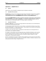
This manual explains how to use the Control Station Modules.
Copyright (C) 2004 Horner APG, LLC., 640 North Sherman Drive Indianapolis, Indiana 46201. All rights
reserved. No part of this publication may be reproduced, transmitted, transcribed, stored in a retrieval
system, or translated into any language or computer language, in any form by any means, electronic,
mechanical, magnetic, optical, chemical, manual or otherwise, without the prior agreement and written
permission of Horner APG, Inc.
All software described in this document or media is also copyrighted material subject to the terms and
conditions of the Horner Software License Agreement.
Information in this document is subject to change without notice and does not represent a commitment on
the part of Horner APG.
Cscape, SmartStack, SmartStix, and CsCAN are trademarks of Horner APG.
DeviceNet is a trademark of the Open DeviceNet Vendor Association (OVDA), Inc.
Ethernet is a trademark of the Xerox Corporation.
For user manual updates, contact Technical Support:
North America:
(317) 916-4274
www.heapg.com
Europe:
(+) 353-21-4321-266
www.horner-apg.com
PAGE 4
MAN0227-08
15 JAN 2010
PREFACE
LIMITED WARRANTY AND LIMITATION OF LIABILITY
Horner APG,LLC. ("HE-APG") warrants to the original purchaser that the Control Station Modules manufactured by
HE-APG is free from defects in material and workmanship under normal use and service. The obligation of HE-APG
under this warranty shall be limited to the repair or exchange of any part or parts which may prove defective under
normal use and service within two (2) years from the date of manufacture or eighteen (18) months from the date of
installation by the original purchaser whichever occurs first, such defect to be disclosed to the satisfaction of HE-APG
after examination by HE-APG of the allegedly defective part or parts. THIS WARRANTY IS EXPRESSLY IN LIEU
OF ALL OTHER WARRANTIES EXPRESSED OR IMPLIED INCLUDING THE WARRANTIES OF
MERCHANTABILITY AND FITNESS FOR USE AND OF ALL OTHER OBLIGATIONS OR LIABILITIES AND HEAPG NEITHER ASSUMES, NOR AUTHORIZES ANY OTHER PERSON TO ASSUME FOR HE-APG, ANY OTHER
LIABILITY IN CONNECTION WITH THE SALE OF THIS Control Station Modules. THIS WARRANTY SHALL
NOT APPLY TO THIS Control Station Modules OR ANY PART THEREOF WHICH HAS BEEN SUBJECT TO
ACCIDENT, NEGLIGENCE, ALTERATION, ABUSE, OR MISUSE.
HE-APG MAKES NO WARRANTY
WHATSOEVER IN RESPECT TO ACCESSORIES OR PARTS NOT SUPPLIED BY HE-APG. THE TERM
"ORIGINAL PURCHASER", AS USED IN THIS WARRANTY, SHALL BE DEEMED TO MEAN THAT PERSON FOR
WHOM THE Control Station Modules IS ORIGINALLY INSTALLED. THIS WARRANTY SHALL APPLY ONLY
WITHIN THE BOUNDARIES OF THE CONTINENTAL UNITED STATES.
In no event, whether as a result of breach of contract, warranty, tort (including negligence) or otherwise, shall HEAPG or its suppliers be liable of any special, consequential, incidental or penal damages including, but not limited to,
loss of profit or revenues, loss of use of the products or any associated equipment, damage to associated equipment,
cost of capital, cost of substitute products, facilities, services or replacement power, down time costs, or claims of
original purchaser's customers for such damages.
To obtain warranty service, return the product to your distributor with a description of the problem, proof of
purchase, post paid, insured and in a suitable package.
ABOUT PROGRAMMING EXAMPLES
Any example programs and program segments in this manual or provided on accompanying diskettes are included
solely for illustrative purposes. Due to the many variables and requirements associated with any particular
installation, Horner APG cannot assume responsibility or liability for actual use based on the examples and diagrams.
It is the sole responsibility of the system designer utilizing the Control Station Modules to appropriately design the
end system, to appropriately integrate the Control Station Modules and to make safety provisions for the end
equipment as is usual and customary in industrial applications as defined in any codes or standards which apply.
Note: The programming examples shown in this manual are for illustrative
purposes only. Proper machine operation is the sole responsibility of the
system integrator.
PREFACE
Revisions to this manual
Revised Table 1.2.
Revised Table 2.7 (LED Description)
15 JAN 2010
PAGE 5
MAN0227-08
PAGE 6
MAN0227-08
15 JAN 2010
PREFACE
PREFACE
15 JAN 2010
PAGE 7
MAN0227-08
Table of Contents
CHAPTER 1 : INTRODUCTION ................................................................................................................ 11
1.1
Scope............................................................................................................................................ 11
1.1.1
Products Covered in this Manual .......................................................................................... 11
1.1.2
Additional References ........................................................................................................... 12
1.2
Operator Control Station (OCS) / Remote Control Station (RCS)................................................ 12
1.2.1
OCS1XX / 2XX Product Description...................................................................................... 12
1.2.2
OCS250 Product Description ................................................................................................ 14
1.2.3
RCS Product Description ...................................................................................................... 14
1.2.4
Cscape Software ................................................................................................................... 15
1.2.5
OCS / RCS Specifications..................................................................................................... 15
1.3
OCS / RCS Resources ................................................................................................................. 16
1.3.1
Overview................................................................................................................................ 16
1.3.2
Resource Limits..................................................................................................................... 17
1.3.3
Resource Definitions ............................................................................................................. 18
1.4
SmartStack Product Description................................................................................................... 23
1.5
Relationship of SmartStack Modules, OCS, RCS and FOX Products ......................................... 23
1.6
Differences Between OCS and RCS ............................................................................................ 24
1.7
Fiber Optic (FOX) Products Description ....................................................................................... 24
1.8
SmartStix Modules (CsCAN Version Only) .................................................................................. 24
1.9
NEMA-Rated Models .................................................................................................................... 25
1.10
Technical Support ..................................................................................................................... 25
CHAPTER 2 : INSTALLATION .................................................................................................................. 27
2.1
General ......................................................................................................................................... 27
2.2
Factors Affecting Panel Layout Design and Clearances .............................................................. 27
2.2.1
Panel Layout Design and Clearance Checklist: .................................................................... 29
2.3
Ports, Connectors and Wiring....................................................................................................... 30
2.3.1
Primary Power Port ............................................................................................................... 30
2.3.2
CAN / DeviceNet Network Port and Wiring ........................................................................... 30
2.3.3
RS-232 Programming Port and Wiring.................................................................................. 33
2.3.4
RS-485 Connector (Graphic OCS250 only) .......................................................................... 35
2.3.5
Modem Setup ........................................................................................................................ 35
2.4
Installing and Removing a SmartStack Module (Shown with the OCS)....................................... 37
2.5
Selecting DeviceNet Network (Firmware Update Wizard)............................................................ 38
2.6
LEDs (OCS / Graphic OCS / RCS Models) .................................................................................. 38
2.6.1
LEDs for OCS / RCS ............................................................................................................. 38
2.6.2
LEDs for Graphic OCS (OCS250)........................................................................................ 40
CHAPTER 3 : OCS1XX AND OCS2XX ..................................................................................................... 41
3.1
General ......................................................................................................................................... 41
3.2
Mounting Orientation .................................................................................................................... 41
3.3
Mounting Requirements ............................................................................................................... 42
3.3.1
Mounting Procedures ............................................................................................................ 42
3.3.2
OCS and SmartStack Dimensions and Panel Cut-outs ........................................................ 42
3.4
OCS Ports, Connectors, and Wiring............................................................................................. 44
3.4.1
Power, Network, and Programming Ports ............................................................................. 44
3.5
Battery Replacement for the OCS1XX / 2XX (HE500BAT005).................................................... 45
CHAPTER 4 : GRAPHIC OCS (OCS250) ................................................................................................. 47
4.1
General ......................................................................................................................................... 47
4.2
Mounting Orientation .................................................................................................................... 47
4.3
Battery Replacement for the Graphic OCS (OCS250) (HE500BAT005) ..................................... 51
CHAPTER 5 : REMOTE CONTROL STATION (RCS) .............................................................................. 53
5.1
General ......................................................................................................................................... 53
5.2
Mounting Orientation .................................................................................................................... 53
5.3
Mounting Instructions.................................................................................................................... 54
PAGE 8
MAN0227-08
15 JAN 2010
PREFACE
5.4
RCS Optional Mounting Bracket (HE800ACC210) ...................................................................... 55
5.5
Dimensions and Panel Cut-Out .................................................................................................... 56
5.6
Connectors ................................................................................................................................... 57
5.5
Battery Replacement for the RCS (HE500BAT005)..................................................................... 57
CHAPTER 6 : OCS / RCS CONFIGURATION (SYSTEM MENU) ............................................................ 59
6.1
General ......................................................................................................................................... 59
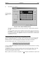
6.2
Navigating Through the System Menu ......................................................................................... 59
6.3
Editing System Menu Screen Fields............................................................................................. 59
6.4
Remote Screen / Keypad (Using Remote Text Terminal and Status Bar) ................................... 60
6.5
Initial System Menu Screens and Self-Test.................................................................................. 60
6.6
Entering the System Menu ........................................................................................................... 60
6.7
Setting RCS Network ID ............................................................................................................... 65
CHAPTER 7 : KEYPAD AND SCREEN..................................................................................................... 69
7.1
Remote Screen and Keypad Capability........................................................................................ 69
7.1.1
Remote Text Terminal........................................................................................................... 69
7.1.2
Cscape Status Bar ................................................................................................................ 69
7.1.3
Establishing Communications using the Remote Text Terminal........................................... 70
7.2
OCS1XX Description .................................................................................................................... 70
7.3
OCS2XX Description .................................................................................................................... 71
7.4
Graphic OCS250 Description ....................................................................................................... 72
7.5
User Screens ................................................................................................................................ 74
7.5.1
Cursor Types (Does Not Apply to Graphic OCS250)............................................................ 74
CHAPTER 8 : SMARTSTACK CONFIGURATION .................................................................................... 75
8.1
General ......................................................................................................................................... 75
8.2
Preliminary Configuration Procedures.......................................................................................... 75
CHAPTER 9 : FIBER OPTIC EXTENSION SYSTEM (FOX104 / FOX404) .............................................. 81
9.1
General ......................................................................................................................................... 81
9.2
FOX Specifications ....................................................................................................................... 81
9.3
Installation..................................................................................................................................... 81
9.3.1
Mounting Orientation ............................................................................................................. 81
9.3.2
Mounting Instructions ............................................................................................................ 82
9.3.2
Dimensions and Hole Pattern................................................................................................ 82
9.4
Ports, Connectors, and Wiring...................................................................................................... 83
9.5
Base ID Switches.......................................................................................................................... 84
9.6
FOX104 / FOX404 LEDs .............................................................................................................. 84
9.7
Example Setups............................................................................................................................ 85
CHAPTER 10 : SMARTSTACK FIBER OPTIC EXPANSION MODULE (FOX100) .................................. 89
10.1
General ..................................................................................................................................... 89
10.2
FOX Specifications and Limitations .......................................................................................... 89
10.3
Connectors / Slot Locations ...................................................................................................... 90
10.4
LEDs ......................................................................................................................................... 90
10.5
Example Setups ........................................................................................................................ 91
CHAPTER 11 : SMARTSTIX I/O ............................................................................................................... 95
11.1
General ..................................................................................................................................... 95
11.2
SmartStix I/O Introduction......................................................................................................... 95
11.3
SmartStix I/O Modules .............................................................................................................. 95
BASIC SMARTSTIX PROGRAMMING ................................................................................................... 96
11.4
Using GET and PUT ................................................................................................................. 96
11.4.1 Get Remote I/O Function Block............................................................................................. 96
11.4.2 Get Remote Parameter Description: ..................................................................................... 96
11.4.3 Put Remote I/O Function Block ............................................................................................. 97
11.4.4 Put Remote Parameter Description:...................................................................................... 98
11.5
SmartStix I/O Default Operation ............................................................................................... 98
ADVANCED SMARTSTIX PROGRAMMING.......................................................................................... 99
11.6
SmartStix I/O Module Device Classes ...................................................................................... 99
11.7
SmartStix I/O Module Consumed (Received) Directed Data.................................................. 100
PREFACE
15 JAN 2010
PAGE 9
MAN0227-08
11.8
Consumed Directed Data Power-Up Initialization................................................................... 101
11.9
SmartStix I/O Module Produced (Transmitted) Global Data................................................... 102
11.10
Produced Global Data Power-Up Initialization........................................................................ 102
11.11
SmartStix I/O Module LED Indicators ..................................................................................... 103
11.11.1
Diagnostic LED Indicators ............................................................................................... 103
11.11.2
Status LED Indicators ...................................................................................................... 103
11.12
SmartStix I/O Module Network ID ........................................................................................... 103
APPENDIX A: NETWORKS..................................................................................................................... 105
APPENDIX B: DISTRIBUTED CONTROL SYSTEMS (DCS) ................................................................. 111
INDEX ....................................................................................................................................................... 113
PAGE 10
MAN0227-08
15 JAN 2010
PREFACE
CH. 1
15 JAN 2010
PAGE 11
MAN0227-08
CHAPTER 1: INTRODUCTION
1.1
Scope
1.1.1
Products Covered in this Manual
The Control Station Hardware User Manual provides information about the following products:
a. Operator Control Station
Graphical Operator Control Station
Remote Control Station
(HE500OCS1xx / OCS2xx),
(HE500OCS250),
(HE800RCS2xx).
The specifications, installation, and configuration procedures of the Operator Control Station (OCS) and the
Remote Control Station (RCS) are covered in detail in this user manual. Information is also provided for the
use of the products in CsCAN and DeviceNet Networks.
b. SmartStack I/O Option Modules
(HE800xxxxxx).
Because there is a wide variety of SmartStack Modules, the focus of the Control Station User Manual is to
provide general installation and configuration data, which is common to all SmartStack Modules. To obtain
specific information regarding SmartStack Modules, refer to the individual data sheets created for each
module in the SmartStack Supplement. (See next section for reference information.)
c. Smartstack Fiber Optic Expansion Module
Fiber Optic Extension System
(HE800FOX100)
(HE800FOX104 / FOX404),
The FOX100 allows an OCS/RCS to connect up to five Fiber Optic Extension bases and hubs (i.e., FOX104
and FOX404).
d. SmartStix Modules for CsCAN Networks
(HE550xxxxxx).
SmartStix is a family of remote products for the OCS. This manual covers programming information for
SmartStix used in CsCAN networks.
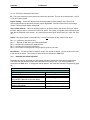
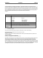
Table 1.1 - – Product Functions
Device
Operator Control Station (OCS)
OCS1XX / 2XX
Graphic OCS250
Remote Control Station (RCS)
RCS2XX
SmartStack Modules
SmartStack Fiber Optic Expansion Module
(FOX100)
Fiber Optic Extension System
(FOX104 / 404)
SmartStix Modules
Control
Yes
Functions
Display
Network
and Keypad
Yes
Yes
I/O
Yes
Remote
Yes
Yes
Only
Provides a wide variety of I/O options for the OCS and RCS.
Require little space and are easy to install. Up to four option
modules are used in each controller.
Allows an OCS110 / OCS210 / OCS250 and RCS250 to
connect up to five Fiber Optic Expansion Systems (e.g.;
FOX404 and FOX104).
Extends a high-speed OCS/RCS backplane enabling
SmartStack I/O Modules to be mounted several meters from
the OCS. The FOX, also, significantly increases the number
of SmartStack I/O modules supported by one OCS/RCS.
Yes
Is a family of remote products for the OCS.
PAGE 12
MAN0227-08
1.1.2
15 JAN 2010
CH.1
Additional References
For further information regarding products covered in this manual, refer to the following references:
a.
SmartStack Modules User Manual (SUP0246) - Contains individual data sheets for each module
and covers specifications, wiring, and configuration.
b.
DeviceNet Implementation Using Control Station Modules (SUP0326) - Covers the
implementation of Control Station products in a DeviceNet network.
c.
Cscape Programming and Reference Manual (MAN0313) – Topics in this manual have been
specifically selected to assist the user through the programming process. It also covers
procedures such as creating graphics using the Graphic OCS and information pertaining to
various models of the OCS / RCS including the Color OCS.
d.
SmartStack Ethernet Module User Manual (SUP0341-02) – Covers the SmartStack Ethernet
Module for use in Ethernet networks.
1.2
Operator Control Station (OCS) / Remote Control Station (RCS)
1.2.1
OCS1XX / 2XX Product Description
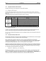
The Operator Control Station (OCS1XX & OCS2XX) provides controller, networking, I/O and operator
interface capabilities in one unit. The OCS can be used in CsCAN or DeviceNet networks. To use the
OCS in a DeviceNet network, a DeviceNet file can be downloaded from Cscape’s Firmware Update
Wizard. (Refer to 38.)
Operator Control Stations have Serial and CAN (Controller Area Network) communication abilities. The
units contain a standard 9-pin RS-232 port for programming/debugging, monitoring and network
administration from an IBM-compatible PC. The OCS1XX and OCS2XX CAN features include CsCAN
(pronounced “See-scan”) peer-to-peer network. CAN-based network hardware is used in the controllers
because of CAN’s automatic error detection, ease of configuration, low-cost of design and implementation
and ability to operate in harsh environments. Networking abilities are built-in to the OCS and require no
external or additional modules. When several Operator Control Stations are networked together to
achieve a specific purpose, the system acts like a large parallel-processing controller.
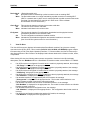
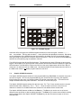
The OCS combines several desirable functions in one compact package. Each unit is a highly integrated
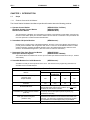
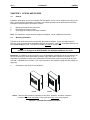
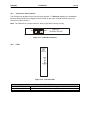
operator interface and controller with expandable I/O and networking capabilities. The OCS1XX features
a 2x20 LCD, 17 keys and fieldbus communications. The OCS2XX features a 4x20 LCD, 32 keys and
fieldbus communications. Both devices have standard features consisting of the following:
CH. 1
•
•
•
•
•
•
•
15 JAN 2010
PAGE 13
MAN0227-08
24 VDC powered
SmartStack I/O Expansion
RS-232 Programming Port
Integrated Bezel
Removable Keypad Inserts
Real-Time Clock
Flash Memory for easy field upgrades
Note: The OCS2XX has a
larger keypad than the
OCS1XX.
OCS100
OCS200
Figure 1.1 - Front View of OCS100 / OCS200
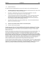
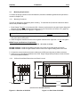
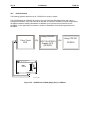
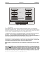
The OCS product line features the ability to pass through programming commands. When attached to an
OCS serial port, a programming package (i.e., Cscape), can access other OCS units connected to a
CsCAN network by passing the programming command through the serial port to the network port. One
Cscape package (connected to one OCS unit) can program all OCS units on the CsCAN network.
CHAPTER 1
PC
Figure 1.2 – Pass-Through Function
(Available in CsCAN Networks Only)
After making a physical serial connection to one OCS, the user must indicate which node is to be
connected (called the TARGET). After that, Cscape and the OCS automatically provide the pass through
connection.
PAGE 14
MAN0227-08
1.2.2
15 JAN 2010
CH.1
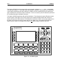
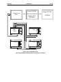
OCS250 Product Description
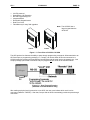
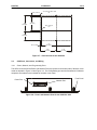
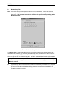
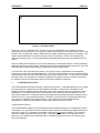
In addition to the features listed in Section 1.2.1, the OCS250 has graphical capabilities.
OCS250-2
Figure 1.3 – Orientation of Graphic OCS
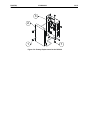
1.2.3
Figure 1.4 – Back View of Graphic OCS
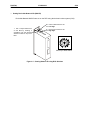
RCS Product Description
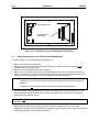
The RCS is similar to an OCS in that it combines local I/O (analog and digital), networking, and a
controller into a single product. Unlike the OCS, the RCS is not equipped with a display and keypad.
Although the RCS does not have a local operator interface, it does support a remote operator interface
through a PC connected to the RCS unit’s serial port or built-in network. The RCS is designed for backplate mounting. (The OCS is mounted on a panel door.) The RCS can be used in CsCAN or DeviceNet
networks. To use the RCS in a DeviceNet network, a DeviceNet file can be downloaded from Cscape’s
Firmware Update Wizard. (Refer to 38.)
RCS
Figure 1.5 - RCS in Panel Box (Shown with Four SmartStack Modules)
CH. 1
1.2.4
15 JAN 2010
PAGE 15
MAN0227-08
Cscape Software
Cscape Software (pronounced “Sea-scape”) is used with the OCS and RCS products (Part #
HE500OSW232). Cscape stands for Control Station Central Application Programming Environment. The
Windows-based software package is easy to use and aids in the integration of a CAN-based Distributed
Control System. The program is used for configuring controllers and SmartStack I/O Modules. Cscape is
also used for programming OCS ladder logic, programming user displays for the OCS, configuring the
network for global digital and analog data, setting system-wide security and monitoring controllers in the
system. Provided there is one serial connection to one node on the network (i.e., CsCAN Network), the
operator has control over the entire system. The operator can upload, download, monitor and debug to
any node on the network.
1.2.5
OCS / RCS Specifications
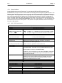
Table 1.2 – Specifications
OCS 1xx,2xx,250 and RCS2xx
Humidity
NEMA Standard
(Note: Does NOT apply to the
RCS2xx.)
Primary Power Range*
Ladder Execution
Typical Execution Speed
CAN Power Range
CAN Power Current
Primary Serial
Secondary Serial (OCS250 only)
CAN
Input / Output
5% to 95% non-condensing
NEMA 4, 12
(Note: UL NEMA 4, 4x, 12 available as an option for OCS100, OCS200 /
210. This option is highly recommended for washdown environment.)
10-30VDC
0.7 ms. per 1K of boolean logic.
12 – 25 VDC
75mA maximum
Standard 9 pin RS-232 for programming, monitoring, and network
administration from a IBM compatible PC
RS-485 or RS-232 – Application Communication Port
CsCAN Network / DeviceNet
Local (All Modules): Maximum of four (4) SmartStack Modules per OCS
Remote (OCS110 / 210/ 250 / or RCS250 Modules):
Keypad (For all models below)
UL (except RCS250)
CE (except RCS250)
OCS 1xx
Operating Temperature
Typical Power Draw *
Inrush Current *
Height
Width
Mounting Depth
User Keys
Keypad
Display
In addition to 4 local I/O modules, up to 20 remote SmartStack I/O Modules
can be connected to an OCS or RCS using five Fiber Optic Bases, which
each contain four I/O slots.
Faceplate made of Autotex polyester by Autotype. The material is
resistant to most corrosive substances found in industrial environments.
The material also holds up well in most industrial conditions. If used
outdoors, the material can yellow or crack.
Class I, Groups A, B, C, D, Division 2
Yes
0°C to +60°C **
160mA @ 24VDC
200mA @ 24VDC for 70mS
5.05” (128.24 mm)
9.05” (229.84 mm)
2.00” (50.80 mm)
17
10 user-programmable keys + Shift, Esc, Enter and 4 direction keys
2x20 LCD w/backlight; 4.84w x 8.06h mm characters
PAGE 16
MAN0227-08
15 JAN 2010
CH.1
continued Table 1.3 – Specifications
OCS 2xx
Operating Temperature
Typical Power Draw *
Inrush Current *
Height
Width
Mounting Depth
User Keys
Keypad
Display
OCS250
Operating Temperature
Typical Power Draw *
Inrush Current *
Height
Width
Mounting Depth
User Keys
Keypad
Display
RCS2xx
Operating Temperature
Typical Power Draw *
Inrush Current*
Height
Width
Mounting Depth
Keypad
0°C to +60°C **
180mA @ 24VDC
270mA @ 24VDC for 1S
7.17” (182.22 mm)
9.05” (229.84 mm)
2.00” (50.80 mm)
32
12 user-programmable keys + Shift, Esc, Enter, 4 direction keys and a full
numeric keypad
4x20 LCD w/backlight ; 4.84w x 8.06h mm characters
0°C to +50°C
350mA @ 24VDC
800mA @24VDC for 50mS.
7 7/8” (200.02 mm)
11 1/8” (282.57 mm)
5 3/16” (131.76 mm)
10 user-programmable keys + Esc, Enter, 4 direction keys and a full numeric
keypad + 8 soft keys.
36
240 x 128 Graphic LCD w / backlight
0°C to +60°C
150mA @ 24VDC
1A @ 24VDC for 8mS
7.00” (177.8 mm)
1.75“ (44.45 mm)
4.00” (101.60 mm)
Although the RCS does not have a local operator interface, it supports a
remote operator interface through a PC connected to the RCS unit’s built-in
network. 32-Key (Remote Only)
Although the RCS does not have local display, it supports a remote operator
Display
interface through a PC connected to the RCS unit’s built-in network.
* These specifications are for OCS, Graphical OCS, and RCS products without any SmartStack I/O Modules
attached. The specifications for the SmartStack Modules can be found in the applicable SmartStack Data
Sheets.
** Although the OCS1XX and OCS2XX withstands the temperature range of 0°C to +60°C, such temperatures
may decrease the life of the display. The recommended rating is 0°C to +50°C.
1.3
OCS / RCS Resources
1.3.1
Overview
This section defines the resource limits of the OCS1XX, OCS2XX, OCS250, and the RCS2xx.
An OCS combines operator interface (display and keypad), local I/O (analog and digital), networking, and
controller, into a single product. In addition, the OCS250 has graphical capabilities. An RCS is a
repackaged OCS, without the operator interface, designed for back-plate mounting. Although the RCS
does not have a local operator interface, it supports a remote operator interface through a PC connected
to the RCS unit’s built-in network or serial port.
The controller portion of the OCS/RCS products is programmed in ladder logic via the Windows-based
Cscape (Control Station Central Application Programming Environment) package. Each OCS or RCS
product provides a set of resources for use by the ladder logic control program as indicated in Table 1.2.
CH. 1
1.3.2
15 JAN 2010
PAGE 17
MAN0227-08
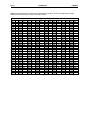
Resource Limits
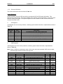
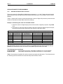
The following table shows the resources available in the OCS100, OCS110, OCS200, OCS210, OCS250,
RCS210 and RCS250 products. Note that although each register type inherently consists of either 1-bit
or 16-bit registers, all registers can be accessed via User Screens and/or Ladder Code as 1, 8, 16 or 32bit values or as ASCII character strings.
Table 1.4 – OCS/RCS Resouce Limits
Resource
%S
%SR
%T
%M
%R
%K
%D
%I
%Q
%AI
%AQ
%IG
%QG
%AIG
%AQG
Network Port
Controllers
Per Network
OCS100
2048
10
200
OCS110
9999
10
200
OCS200
2048
12
200
OCS210
OCS250
8
192
2048
2048
9999
9999
12
10
200
300
2048
2048
512
512
64 / 0
64 / 0
32 / 16
32 / 16
CsCAN / DeviceNet
RCS210
RCS250
2048
12
200
9999
12
200
253 / 64
SmartStack
I/O Modules
4 Slots
4 Slots
(23 with
FOX)
4 Slots
4 Slots
(23 with
FOX)
4 Slots (23
with FOX)
4 Slots
Keypad
17 Keys
17 Keys
32 Keys
32 Keys
36 Keys
32 Keys
(Remote
Only)
4 Slots
(23 with
FOX)
32 Keys
(Remote
Only)
Display
2x20
Chars
(Text LCD)
2x20
Chars
(Text LCD)
4x20
Chars
(Text
LCD)
4x20
Chars
(Text
LCD)
128x240
Pixels
(Graphics
LCD)
4x20 Chars
(Remote
Only)
4x20 Chars
(Remote
Only)
64K
128K
64K
128K
2M
64K
128K
200
200
200
200
300
200
200
16
16
16
16
50
16
16
Screen
Memory
User Screens
Data Fields
Per
User Screen
Text Tables
Items Per
Text Table
Ladder Code
200
20
20
20
20
Unlimited
20
20
64K
128K
64K
128K
128K
64K
128K
PAGE 18
MAN0227-08
1.3.3
15 JAN 2010
CH.1
Resource Definitions
This section defines the resources listed in Table 1.4.
System Registers
System Registers (%S and %SR) are used to store general OCS or RCS status information. This
information is used internally, and is also available to the operator via the System Menu, using the Control
Station’s display and keypad. The System Registers are also available for User Screens and can be
accessed by Ladder Code.
a.
%S Registers
%S Registers are 1-bit memory locations, containing system status information, implemented as shown in
Table 1.5.
Register
%S1
%S2
%S3
%S4
%S5
%S6
%S7
%S8
b.
Name
FST_SCN
NET_OK
T_10MS
T_100MS
T_SEC
IO_OK
ALW_ON
ALW_OFF
Table 1.5 - %S Registers
Description
On during first scan after entering RUN mode
On if Network is functioning properly
On for 5 mS; Off for 5 mS
On for 50 mS; Off for 50 mS
On for 500 mS; Off for 500 mS
On if SmartStack I/O is configured properly
Always On
Always Off
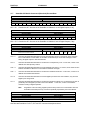
%SR Registers
%SR Registers are 16-bit memory locations, containing system status information, implemented as
shown in Table 1.6.
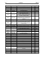
Note: Where 2 %SRs are combined to make a 32-bit value, the lower-numbered %SR is the low word,
while the higher-numbered %SR is the high word.
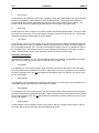
Table 1.6 - %SR Registers
Register
%SR1
%SR2
%SR3
%SR4
Name
USER_SCR
ALRM_SCR
SYS_SCR
SELF_TEST
%SR5
CS_MODE
%SR6
%SR7
%SR8
%SR9-10
%SR11-12
%SR13-14
%SR15-16
%SR17-18
%SR19-20
%SR21-22
%SR23
SCAN_RATE
MIN_RATE
MAX_RATE
EDIT_BUF
LADDER_SIZE
UTXT_SIZE
Reserved
IO_SIZE
NET_SIZE
SD_SIZE
LADDER_CRC
Description
Current User Screen Number (0=none)
Current Alarm Screen Number (0=none)
Current System Screen Number (0=none)
Bit-Mapped Self-Test Result
Control Station Mode
(0=Idle, 1=Do I/O, 2=Run)
Average Scan Rate (in tenths of mS)
Minimum Scan Rate (in tenths of mS)
Maximum Scan Rate (in tenths of mS)
Data Field Edit Buffer
Ladder Code Size
User Text Screen Table Size
I/O Configuration Table Size
Network Configuration Table Size
Security Data Table Size
Ladder Code CRC
Min
0
0
0
0
Max
300
300
11
65535
0
2
0
2
4
16
34
0
1000
1000
1000
32
2 -1
64K
64K
64K
32K
65535
CH. 1
15 JAN 2010
PAGE 19
MAN0227-08
Table 1.6 - %SR Registers
Register
%SR24
%SR25
%SR26
%SR27
%SR28
Name
UTXT_CRC
Reserved
IO_CRC
NET_CRC
SD_CRC
%SR29
NET_ID
%SR30
NET_BAUD
%SR31
NET_MODE
%SR32
%SR33
LCD_CONT
FKEY_MODE
%SR34
SERIAL_PROT
%SR35-36
%SR37
%SR38
%SR39
%SR40
SERIAL_NUM
MODEL_NUM
ENG_REV
BIOS_REV
FPGA_REV
%SR41
LCD_COLS
%SR42
LCD_ROWS
%SR43
KEY_TYPE
%SR44
%SR45
%SR46
%SR47
%SR48
%SR49
%SR50
%SR51
%SR52
%SR53-54
%SR55
%SR56
%SR57
%SR58
%SR59
%SR60
RTC_SEC
RTC_MIN
RTC_HOUR
RTC_DATE
RTC_MON
RTC_YEAR
RTC_DAY
NET_CNT
WDOG_CNT
BAD_LADDER
F_SELF_TEST
LAST_KEY
BAK_LITE
USER_LEDS
S_ENG_REV
S_BIOS_REV
%SR61
NUM_IDS
%SR62-64
%SR65-76
%SR77-88
%SR89-100
%SR101-112
Reserved
SS_INFO_1
SS_INFO_2
SS_INFO_3
SS_INFO_4
Description
User Text Screen Table CRC
I/O Configuration Table CRC
Network Configuration Table CRC
Security Data Table CRC
This Station’s Primary Network ID (CsCAN)
This Station’s Primary Network ID (DeviceNet)
Network Baud Rate (CsCAN)
(0=125KB; 1=250KB; 2=500KB; 3=1MB)
Network Baud Rate (DeviceNet)
(0=125KB; 1=250KB; 2=500KB)
Network Mode
(0=Network Not Required; 1=Network Required;
2=Reserved; 3=Network Required and
Optimized)
LCD Display Contrast Setting
Function Key Mode (0=Momentary; 1=Toggle)
RS232 Serial Protocol Mode
(0=Firmware Update (RISM); 1=CsCAN;
2=Generic (Ladder- Controlled); 3=Modbus RTU;
4=Modbus ASCII)
This Station’s 32-bit Serial Number
This Station’s Binary Model Number
Main CPU Engine Firmware Rev Number x 100
Main CPU BIOS Firmware Rev Number x 100
FPGA Image Rev Number x 10
LCD Text Display Number of Columns
LCD Graphics Display Number of Columns
LCD Text Display Number of Rows
LCD Graphics Display Number of Rows
Keypad Type
(0=16 Keys; 1=17 Keys; 2=32 Keys; 3=36 Keys)
Real-Time-Clock Second
Real-Time-Clock Minute
Real-Time-Clock Hour
Real-Time-Clock Date
Real-Time-Clock Month
Real-Time-Clock Year
Real-Time-Clock Day (1=Sunday)
Network Error Count
Watchdog-Tripped Error Count
Bad Ladder Code Error Index
Filtered Bit-Mapped Self-Test Result
Key Code of Last Key Press or Release
LCD Backlight On/Off Switch (0=Off; 1=On)
User LED Control / Status
Slave CPU Engine Firmware Rev Number x 100
Slave CPU BIOS Firmware Rev Number x 100
This Station’s Number of Network IDs (CsCAN)
This Station’s Number of Network IDs
(DeviceNet)
SmartStack I/O Module #1 Information Structure
SmartStack I/O Module #2 Information Structure
SmartStack I/O Module #3 Information Structure
SmartStack I/O Module #4 Information Structure
Min
0
0
0
0
1
0
Max
65535
65535
65535
65535
253
63
0
3
0
2
0
3
0
0
255
1
0
4
0
0
0000
0000
000
20
240
2
128
2 -1
65535
9999
9999
255
20
240
4
128
0
3
0
0
0
1
1
1996
1
0
0
0
0
0
0
0
0000
0000
1
59
59
23
31
12
2095
7
65535
65535
65534
65535
255
1
65535
9999
9999
253
1
1
-
-
32
PAGE 20
MAN0227-08
15 JAN 2010
CH.1
Table 1.6 - %SR Registers
Register
%SR113-114
%SR115-116
%SR117-118
%SR119-120
%SR121-122
%SR123-124
%SR125
%SR126
%SR127
%SR128
%SR129
%SR130-192
Name
GOBJ_SIZE
GSTR_SIZE
GBMP_SIZE
GTXT_SIZE
GFNT_SIZE
Reserved
GOBJ_CRC
GSTR_CRC
GBMP_CRC
GTXT_CRC
GFNT_CRC
Reserved
Description
Graphics Object Table Size
Graphics String Table Size
Graphics Bitmap Table Size
Graphics Text Table Size
Graphics Font Table Size
Graphics Object Table CRC
Graphics String Table CRC
Graphics Bitmap Table CRC
Graphics Text Table CRC
Graphics Font Table CRC
-
Min
8
8
8
8
8
0
0
0
0
0
-
Max
128K
128K
256K
128K
128K
65535
65535
65535
65535
65535
-
User Registers
User Registers (%T, %M and %R) are used to store application-specific OCS or RCS data. This data can
be accessed via User Screens and/or by Ladder Code.
a.
%T Register
A %T Register is a non-retentive 1-bit memory location used to store application-specific state
information.
b.
%M Registers
A %M Register is a retentive 1-bit memory location used to store application-specific state information.
c.
%R Registers
A %R Register is a retentive 16-bit memory location used to store application-specific values.
HMI Registers
HMI Registers (%K and %D) give the user access to the OCS or RCS keypad and display.
The MiniOCS, OCS1XX and OCS2XX have membrane keypads and text-based LCD displays, allowing
the operator to enter and display general and application-specific information. This same information can
be entered and displayed via a remote PC, using Cscape’s Remote Display Terminal function, if the PC is
connected as a CsCAN Host device. The RCS does not have a local keypad or display, but it still
supports Cscape’s Remote Display Terminal function. The OCS250 has a membrane keypad and a
graphics-based LCD display, but it does not yet support the Cscape Remote Display Terminal function.
a.
%K Registers
A %K Register is a non-retentive 1-bit memory location (contact), used to store the state of a function key
on the Control Station’s keypad. If the function keys are set for momentary mode, a function key’s
associated %K register will be ON as long as the function key is pressed. If the function keys are set for
toggle mode, a function key’s associated %K register will toggle each time the function key is pressed.
b.
%D Registers
A %D Register is a non-retentive 1-bit memory location (coil), which can be turned ON by Ladder Code to
cause the corresponding User or Alarm Screen to be displayed.
CH. 1
c.
15 JAN 2010
PAGE 21
MAN0227-08
User Screens
A User Screen is a combination of fixed text or graphics, along with variable Data Fields (called Graphics
Objects in the OCS250), which together fill the LCD display screen. These screens are defined via
Cscape dialogs and are then downloaded and stored into the Control Station’s Flash memory. User
Screens can be selected for display by operator entries on the keypad or by Ladder Code.
d.
Data Fields
A Data Field is an area on a User Screen where variable data is displayed and edited. The source data
for a Data Field can be any of the Control Station’s Register resources as defined above. The field size
and display format is programmable via Cscape dialogs.
e.
Text Tables
A Text Table is a list of Text Items, which can be used in a Data Field, to display descriptive words and
phrases to describe the value of a Register, instead of displaying numeric values. A simple example of
this, would allow the strings “OFF” and “ON” to be displayed, instead of 0 and 1, to describe the state of
the %I4 digital input. The maximum number of Text Tables and Text Items per Text Table is shown in
Table 1, but the number can be further limited by overall User Screen memory usage.
SmartStack I/O Registers
SmartStack I/O Registers (%I, %Q, %AI and %AQ) give the user access to the SmartStack I/O Module
data. This data can be accessed via User Screens and/or by Ladder Code.
a.
%I Registers
A %I Register is a 1-bit memory location, which is normally used to store the state of one of the digital
inputs associated with a SmartStack I/O module. When used in this way, %I registers are non-retentive.
All extra %I registers, which are not associated with SmartStack inputs, are retentive, and can be used
just like %M registers.
b.
%Q Registers
A %Q Register is a non-retentive 1-bit memory location, which is normally used to store the state of one
of the digital outputs associated with a SmartStack I/O module.
c.
%AI Registers
A %AI Register is a 16-bit memory location, which is normally used to store the value of one of analog
inputs associated with a SmartStack I/O module. When used in this way, %AI registers are non-retentive.
All extra %AI registers (which are not associated with SmartStack inputs) are retentive and can be used
just like %R registers.
d.
%AQ Registers
A %AQ Register is a non-retentive 16-bit memory location, which is normally used to store the value of
one of the analog outputs associated with a SmartStack I/O module.
PAGE 22
MAN0227-08
e.
Local:
15 JAN 2010
CH.1
SmartStack I/O Modules
Up to 4 SmartStack I/O Modules can be plugged into an OCS or RCS, to provide local digital
and analog I/O, and/or intelligent I/O, such as ASCII-Basic, High-Speed Counter, Stepper
Motor Indexer, Power Monitor and Ethernet communication.
Remote: In addition to local I/O modules, up to 20 remote SmartStack I/O Modules can be connected to
an OCS or RCS using five Fiber Optic Bases, which each contain four I/O slots. If a remote I/O
connection is desired, the SmartStack FOX100 module must occupy the local OCS110 / 210/
250 / or RCS250 Slot 1 position.
Note: Fiber Optic Base modules include the FOX104 and FOX404.
Global Data I/O Registers
Global Data I/O Registers (%IG, %QG, %AIG and %AQG) give the user access to the Network Port’s
Global I/O data. This data can be accessed via User Screens and/or by Ladder Code.
a.
%IG Registers
A %IG Register is a retentive 1-bit memory location, which is normally used to store a global digital state
obtained from another Control Station on the network.
b.
%QG Registers
A %QG Register is a retentive 1-bit memory location, which is normally used to store a digital state to be
sent as global data to the other Control Stations on the network.
c.
%AIG Registers
A %AIG Register is a retentive 16-bit memory location, which is normally used to store a global analog
value obtained from another Control Station on the network.
d.
%AQG Registers
A %AQG Register is a retentive 16-bit memory location, which is normally used to store an analog value
to be sent as global data to the other Control Stations on the network.
e.
Network Port
The CsCAN Network is based on the Bosch Control Area Network (CAN), and implements the CsCAN
Protocol which is designed to take maximum advantage of the global data broadcasting capability of
CAN. Using this network protocol, up to 64 Control Stations can be linked without repeaters, and up to
253 Control Stations can be linked by using 3 repeaters. For more information regarding CsCAN
Protocol, refer to the CsCAN Protocol Specification document.
DeviceNet is an open higher-layer protocol, which is supported by products from multiple vendors. In an
OCS or RCS, DeviceNet can be loaded as a replacement for the CsCAN Protocol Message Layer, and as
a result, the OCS or RCS becomes a DeviceNet Slave device. Note that the OCS or RCS still
implements the CsCAN Protocol Command Layer with respect to the RS232 programming port. For more
information regarding DeviceNet Protocol, refer to the OCS and RCS Communication Capabilities
document, or contact the DeviceNet governing body (ODVA).
CH. 1
15 JAN 2010
PAGE 23
MAN0227-08
Ladder Code
The Ladder Code, stores ladder instructions generated by Cscape. This Ladder Code is downloaded and
stored into the Control Station’s Flash memory, to be executed each controller scan, when the controller
is in RUN mode.
1.4
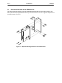
SmartStack Product Description
The SmartStack Modules provide a wide variety of I/O options for all OCS models and the RCS.
Compact and easy to install, SmartStack Modules are used in a multitude of control applications. Up to
four Smart Stack Modules can be installed in each device.
Figure 1.6 - Back View of OCS (Shown with Four SmartStack Modules)
1.5
Relationship of SmartStack Modules, OCS, RCS and FOX Products
SmartStack Modules provide all models of the OCS and RCS with I/O capability. Up to four SmartStack
modules can be used with each OCS and RCS. The OCS and RCS have networking capabilities
allowing communication with each other. Fiber Optic (FOX) products extend the distance and the number
of SmartStacks that can be used.
PAGE 24
MAN0227-08
1.6
15 JAN 2010
CH.1
Differences Between OCS and RCS
Although the OCS models and RCS have control capabilities (via Ladder Logic programming), the OCS
models have two key features the RCS does not have including a keypad and a display interface. In
place of a keypad to perform functions such as setting the Network ID, two switches on the RCS are
used. Two additional LEDs have been added to the RCS (MS and NS lamps) to provide diagnostic
information. The RCS has a 3-pin power connector while the OCS has a 2-pin power connector.
The OCS incorporates alphanumeric LCD displays with backlights for the purpose of conveying
information to the operator. This same function is available on a remote PC (using Cscape’s Remote
Text Term function) if the PC is connected to the CsCAN network. The RCS does not have a local
display, but it still supports Cscape’s Remote Text Term function.
1.7
Fiber Optic (FOX) Products Description
Two categories of Fiber Optic products are available to support Control Station Modules as specified in
this section.
a.
Fiber Optic Expansion System
The Fiber Optic Extension System extends a high-speed OCS backplane enabling SmartStack I/O
Modules to be mounted several meters from the OCS. The FOX, also, significantly increases the number
of SmartStack I/O modules supported by one OCS.
HE800FOX104
HE800FOX404
b.
Each FOX Base supports 4 SmartStack Modules.
Each FOX Supports 4 SmartStack Modules plus 4 additional I/O Bases.
SmartStack Fiber Optic Extension Module (Used with OCS110/210/250 and RCS250)
The SmartStack Fiber Optic Extension Module (HE800FOX100) allows an OCS110 / OCS210 / OCS250
and RCS250 to connect up to five Fiber Optic Expansion Systems (e.g.; FOX404 and FOX104).
1.8
SmartStix Modules (CsCAN Version Only)
The SmartStix Modules are a family of remote products designed for the OCS in CsCAN networks.
Additional versions of SmartStix modules are available for use in other networks, but those versions are
not within the scope of this manual. (If SmartStix is used with DeviceNet, Modbus, or Profibus networks,
refer to the SmartStix Fieldbus Supplement. [SUP0552]).
CH. 1
1.9
15 JAN 2010
PAGE 25
MAN0227-08
NEMA-Rated Models
The following products carry UL NEMA ratings for Enclosure Evaluation for Type 4, 4x, 12 Ratings when
installed in a Type 4, 4x or 12 Rated Enclosure.
These products contain keypad inserts.
OCS100-18
OCS110-18
OCS200-18
OCS210-18
These products do not contain keypad inserts.
OCS100-19
OCS110-19
OCS200-19
OCS210-19
Refer to the installation chapters for each product to determine Torque specifications.
1.10
Technical Support
For assistance, contact Technical Support at the following locations:
North America:
(317) 916-4274
www.heapg.com
Europe:
(+) 353-21-4321-266
www.horner-apg.com
PAGE 26
MAN0227-08
15 JAN 2010
NOTES
CH.1
CH. 2
15 JAN 2010
PAGE 27
MAN0227-08
CHAPTER 2: INSTALLATION
2.1
General
Installation information is covered in Chapter Two that applies to one or more models of the OCS or the
RCS. Product-specific information is covered in individual chapters for the various products discussed in
this manual. Examples of product-specific information includes:
a.
b.
c.
Dimensions and panel cut-outs
Mounting instructions and orientation
Some types of connectors and other hardware
Note: It is important to consult both this chapter and the individual product chapter for installation
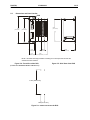
information.
2.2
Factors Affecting Panel Layout Design and Clearances
Warning: It is important to follow the requirements of the panel manufacturer and to follow
applicable electrical codes and standards.
The designer of a panel layout needs to assess the requirements of a particular system and to consider
the following design factors. A convenient checklist is provided in Section 2.2.1.
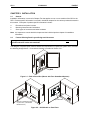
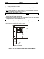
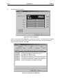
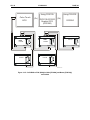
RCS
Figure 2.1 – RCS in Panel Box (Shown with Four SmartStack Options)
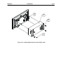
Graphic OCS250
OCS100 or OCS200 mounted
on panel door. (4 SmartStack
Modules shown.)
Figure 2.2 – OCS Models on Panel Door
OCS250-2
PAGE 28
MAN0227-08
a.
15 JAN 2010
CH. 2
Clearance / Adequate Space
Install devices to allow sufficient clearance to open and close the panel door.
Table 2.1 – Minimum Clearance Requirements for Panel Box and Door
Minimum Distance between base of device and sides of cabinet
2 inches (50.80 mm)
Minimum Distance between base of device and wiring ducts
1.5 inches (38.10 mm)
If more than one device installed in panel box (or on door):
4 inches (101.60 mm)
Minimum Distance between bases of each device
between bases of each device
When door is closed:
2 inches
Minimum distance between device and closed door
(50.80 mm)
(Be sure to allow enough depth for SmartStack Modules.)
To allow optimum use of the SmartStack Module Options:
Refer to Figures 2.1 –2.9 for
Up to four SmartStack Modules may be installed in each OCS or
OCS and SmartStack
RCS. It is important to consider the depth required in a panel
dimensions.
box to allow optimum use of the SmartStack Options.
b.
Grounding
Warning: Be sure to meet the ground requirements of the panel manufacturer and also meet
applicable electrical codes and standards.
Panel box: The panel box needs to be properly connected to earth ground to provide a good common
ground reference.
Panel door: Tie a low impedance ground strap between the panel box and the panel door to ensure that
they have the same ground reference.
Devices in panel box and on the panel box door:
1. Use the mounting hardware provided with the device, which includes star washers.
2. Remove the paint (to bare metal) around the screw holes where star washers will be placed when
installing the device. Clean the bare metal and ensure that it is free of dust and other particles.
Note: Remove paint from screw holes located inside the panel box and the interior of the panel box door.
These locations are where the star washers actually come in contact with the bare metal.
3. Use the star washers on the mounting stud of the device to provide better contact between the
mounting hardware and the panel surface. Ensure that a good solid contact is made against bare metal
for proper grounding.
CH. 2
c.
15 JAN 2010
PAGE 29
MAN0227-08
Temperature / Ventilation
Ensure that the panel layout design allows for adequate ventilation and maintains the specified ambient
temperature range. Consider the impact on the design of the panel layout if operating at the extreme
ends of the ambient temperature range. For example, if it is determined that a cooling device is required,
allow adequate space and clearances for the device in the panel box or on the panel door.
d.
Orientation
Observe guidelines for proper orientation of the bases when mounting the OCS and RCS. (Refer to
individual product chapters.) Proper orientation helps to ensure a good connection when SmartStack
Modules are installed into the devices.
e.
Noise
Consider the impact on the panel layout design and clearance requirements if noise suppression devices
are needed. Be sure to maintain an adequate distance between the OCS or RCS and noisy devices such
as relays, motor starters, etc.
Note: Do not route power and signal wires in the same conduit.
f.
NEMA Ratings
To meet NEMA for Enclosure Evaluation for Type 4, 4x, 12 Ratings, products must be installed in a Type
4, 4x or 12 Rated Enclosure.
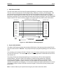
2.2.1
Panel Layout Design and Clearance Checklist:
The following list provides highlights of panel layout design factors discussed in Section 2.2 (page 27).
____Meets the electrical code and applicable standards for proper grounding, etc.?
____Meets the panel manufacturer’s requirements for grounding, etc.?
____Is the panel box properly connected to earth ground? Is the panel door properly grounded? Has the
appropriate procedure been followed to properly ground the devices in the panel box and on the
panel door? (See page 29.)
____Are minimum clearance requirements met? (See Table 2.1.) Can the panel door be easily opened
and closed? Is there adequate space between device bases as well as the sides of the panel and
wiring ducts?
____Is the panel box deep enough to accommodate the optimum use of the SmartStack Option
Modules? Up to four SmartStack Modules may be installed in each OCS. (Refer to individual
product chapters containing dimension figures and panel cut-outs.)
____Are the device bases oriented correctly? The OCS devices are mounted on the door of a panel box.
____Is there adequate ventilation? Is the ambient temperature range maintained? Are cooling or heating
devices required?
____Are noise suppression devices or isolation transformers required? Is there adequate distance
between the base of the OCS or RCS and noisy devices such as relays or motor starters? Ensure
that power and signal wires are not routed in the same conduit.
PAGE 30
MAN0227-08
15 JAN 2010
CH. 2
____Are there other requirements that impact the particular system, which need to be considered?
____If applicable, does the enclosure meet NEMA requirements? (See Section 2.2 [Item f].)
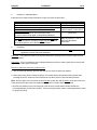
2.3
Ports, Connectors and Wiring
Note: For RCS Primary Power Port, refer to Section 5.6 Connectors.
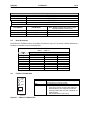
2.3.1
Primary Power Port
Table 2.2 – Primary Power Port Pins
Pin
1
2
Signal
V+
V-
Description
Input power supply voltage
Input power supply ground
Pin 1
Pin 2
Pin 1
Pin 2
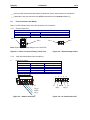
Note: Power Supply Voltage Range is from 10-30 VDC.
Figure 2.3 - Power Connector (Primary Power Port)
2.3.2
CAN / DeviceNet Network Port and Wiring
a.
Network Connector
Figure 2.4 – Viewed looking at OCS
Table 2.3– CAN Port Pins
Pin
1
2
3
4
5
1 2
3
Signal
VCN_L
SHLD
CN_H
V+
4
Description
Power Signal Shield
Signal +
Power +
1
5
V+
CN_H
SHLD
CN_L
VFigure 2.5 – Network Connector
V-
2
3
4
5
V+
SHLD
CN_L
CN_H
Figure 2.6 – As viewed at the OCS
CH. 2
PAGE 31
MAN0227-08
VCN_L
SHIELD
CN_H
V+
VCN_L
SHIELD
CN_H
V+
VCN_L
SHIELD
CN_H
V+
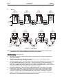
Wiring
VCN_L
SHIELD
CN_H
V+
b.
15 JAN 2010
121Ω
121Ω
+
12-25VDC
RED
CN_H
V+
SHIELD
121Ω
BLU
WHT
WHT
RED
VCN_L
V+
SHIELD
CN_H
BLK
BLU
WHT
BLK
BLU
RED
SHIELD
WHT
BLK
BLK
BLU
121Ω
VCN_L
V+
SHIELD
CN_H
VCN_L
V+
SHIELD
CN_H
V-
CN_L
-
RED
SHIELD
SHIELD
+
12-25VDC
Figure 2.7 – CAN Wiring
Note: To optimize CAN network reliability in electrically noisy environments, the CAN power
supply needs to be isolated (dedicated) from the primary power.
CAN Wiring Rules (See Figure 2.7.)
1.
2.
3.
4.
5.
Wire the CAN network in a daisy-chained fashion such that there are exactly two physical endpoints on the network.
The two nodes at the physical end-points need to have 121 ohm 1% terminating resistors
connected across the CN_L and CN_H terminals.
Use data conductors (CN_L and CN_H) that are 24 AWG shielded twisted pair for “thin cable” and
22 AWG shielded twisted pair for “thick cable.” They must also have 120-ohm characteristic
impedance. In typical industrial environments, use a Belden wire #3084A (“thin”). Use #3082A
(“thick”) for network cable lengths greater than 100 meters environments where noise is a concern.
Place data conductors (CN_L and CN_H) into a twisted pair together.
Use power conductors (V- and V+) that are 18 AWG twisted-pair for “thin cable” and 15 AWG
twisted-pair for “thick cable.” Place power conductors (V- and V+) into a twisted pair together.
If local codes require the local CAN power supply to be earth grounded, connect the V- power
conductor to a good earth ground at one place only on the network, preferably at a physical
endpoint. If multiple power supplies are used, only one power supply must have V- connected to
earth ground. The remaining power supplies need to be isolated.
PAGE 32
MAN0227-08
6.
7.
8.
c.
15 JAN 2010
CH. 2
For a section of cable between two nodes, the cable shield is connected to the cable shield input at
one end of the cable only.
A CAN network (without repeaters) is limited to 64 nodes (with 63 cable segments) with a maximum
combined cable length of 1500 ft. at 125KBaud.
Up to four CAN network segments, which adhere to the above rules, may be connected together
using three CAN repeaters. In this manner, a CAN network may be extended to 253 nodes with a
total cable distance of 6000 ft. at 125KBaud.
CsCAN or DeviceNet Cable
Note: For more details about DeviceNet networks, refer to DeviceNet Implementation Using Control
Station Modules.
The 5-wire, multi-conductor copper cable used in CsCAN or DeviceNet network include:
1. Two wires used as a transmission line for network communications.
2. Two wires used to transmit network power.
3. One conductor used as an electromagnetic shield.
Cabling is available in a variety of current-carrying capacities. On a CsCAN or DeviceNet fieldbus, every
device must, at least, power its network transceivers from the network power supply. Some devices draw
all of their power from the network supply. In CsCAN or DeviceNet, thick and thin cable is used as
indicated:
1. Thick cable: Use for long distances and more power. Usually used for Trunk cable.
2. Thin cable: Use for shorter distances. Usually used for drop cables or where cable flexibility is
needed.
Table 2.4 - CsCAN / DeviceNet Cable Specifications
Thick Cable –
general specifications
(e.g., Belden 3082A)
Two twisted shielded pairs –Common axis with drain wire in center.
One signal pair (#18), blue/white; One power power pair (#15) black/red.
Separate aluminized mylar shields around power pair and signal pair.
Overall foil/braid shield with drain wire (#18), bare*. High Speed (Vp=75%
min),
low loss, low distortion, data pair (to keep propagation delays to a
minimum).
8 amp maximum current capacity. PVC insulation on power pair.
Industrial temperature range. High flexibility.
Thin Cable –
Two twisted shielded pairs –Common axis with drain wire in center.
general specifications
One signal pair (#24), blue/white; One power power pair (#22) black/red.
(e.g., Belden 3084A)
Separate aluminized mylar shields around power pair and signal pair.
Overall foil/braid shield with drain wire (#22), bare*. High Speed (Vp=75%
min), low loss, low distortion, data pair (to keep propagation delays to a
minimum).
3 amp maximum current capacity. PVC insulation on power pair.
Industrial temperature range. High flexibility
Network Topology
Bus with limited branching (truckline / dropline)
Redundancy
Not Supported
Network Power for Node devices
Nominal 24 VDC ±4%
Allowed Nodes (Bridging excluded) 64 nodes
Data Packet Size
0-8 bytes with allowance for message fragmentation
Duplicate Address Detection
Addresses verified at power-up
Error Detection / Correction
CRC – retransmission of message if validity not acknowledged by
recipient.
* The drain wire connects shields within the cable and serves as a means to terminate the shield into the
connector.
CH. 2
d.
15 JAN 2010
PAGE 33
MAN0227-08
Bus Length
Several factors affect the maximum length of the bus including the accumulated length of drop lines,
cable type, transfer rate and the number of drop lines. Although a branch is limited to one network per
drop, it can have multiple ports. A branch can not exceed 6 meters.
Table 2.5 - CAN Network Baudrate vs. Total Cable Length
Note: The following values apply to both CsCAN or DeviceNet except as indicated.
Thick Cable: Network Data Rate
Maximum Total Cable Length
1Mbit / sec. (Does not apply to DeviceNet.)
40m (131 feet)
500Kbit / sec.
100m (328 feet)
250Kbit / sec.
200m (656 feet)
125Kbit / sec.
500m (1,640 feet)
Thin Cable Maximum Total Cable Length
Maximum bus length is independent of network data rate. Maximum bus length is 100m.
e.
Bus Power and Grounding
When using CsCAN or DeviceNet:
1. A power supply of 24VDC (±4%) at 16A maximum is required for use in a CsCAN / DeviceNet network
2. With thick cable, a single network segment can have a maximum of 8A. To do this, the power supply
needs to be located in the center of two network segments.
3. Thin cable has maximum of 3A.
4. To ground the cable shield, connect to pin 3 as shown in Figure 2.8.
5. If local codes require the local CAN power supply to be earth grounded, connect the V- power
conductor to a good earth ground at one place only on the network, preferably at a physical endpoint.
If multiple power supplies are used, only one power supply must have V- connected to earth ground.
The remaining power supplies need to be isolated.
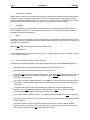
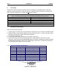
2.3.3
RS-232 Programming Port and Wiring
Table 2.6 – RS-232 Port Pins
Pin
Signal
Description
1
DCD
Always high
2
RXD
Received Data
3
TXD
Transmitted Data
4
DTR
Data Terminal Ready
5
GND
Ground
6
DSR
Data Set Ready
7
RTS
Request to Send
8
CTS
Clear to Send
9
RI
Ring Indicate
Pin 1
Direction
Out
Out
In
In
Out
In
Out
Out
Pin 9
Figure 2.8 – RS-232 Port
PAGE 34
MAN0227-08
15 JAN 2010
CH. 2
a. OCS1XX and OCS2XX
The OCS units feature an RS-232 port (Programming/Debug) for connection to a personal computer.
This port is used for the purposes of OCS programming, configuring, monitoring, and debugging. This
port can also be used for general ladder logic controlled serial communications to printers, modems,
terminals, etc. When ladder has control of this port, it is not available for programming or debugging. If a
permanent connection is to be made between the OCS and the personal computer, the use of a shielded,
multiple conductor wire with a maximum length of 15.24 meters (50 feet) enables proper performance.
SHIELDED MULTI CONDUCTOR
OCS RS-232
9-PIN PC COM
DCD 1
1 DCD
RXD 2
2 RXD
TXD 3
3 TXD
DTR 4
4 DTR
GND 5
5 GND
DSR 6
6 DSR
RTS 7
7 RTS
CTS 8
8 CTS
RI 9
9 RI
DB9
MALE
15.24 METERS MAX
(50 FEET MAX)
DB9
FEMALE
Figure 2.9 – OCS RS-232 to PC Wiring Diagram
b. Graphic OCS (OCS250)
The Graphic OCS features primary and secondary RS-232 ports. Both primary and secondary RS-232
port pin-outs are shown in Table 2.6. The primary RS-232 port (Programming/Debug) is for connection to
a PC.
The secondary port includes an RS-232 or RS-485. Only one of these secondary ports can be selected
for use at any given time. The secondary serial port is used for application communications such as bar
code readers, etc.
The primary RS-232 port (Programming/Debug) is for connection to a PC as well as application
communications. This port is used for the purposes of Graphic OCS programming, configuring,
monitoring, and debugging. This port can also be used for general ladder logic controlled serial
communications to printers, modems, terminals, etc. When ladder has control of this port, it is not
available for programming or debugging. For connection between the Graphic OCS and the PC, the use
of a shielded, multiple conductor wire with a maximum length of 15.24 meters (50 feet) enables proper
performance.
Note: A shorter cable may be required when using the port at baud rates above 9600.
CH. 2
2.3.4
15 JAN 2010
PAGE 35
MAN0227-08
RS-485 Connector (Graphic OCS250 only)
1
2
RXD+
RXD-
3
4
5
6
GND
TXD+
TXD-
Figure 2.10 - RS-485 Connector (Graphic OCS only.)
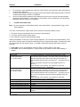
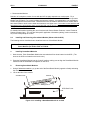
2.3.5
Modem Setup
A modem can be used for remote communications between a computer (using Cscape Software) and the
OCS. The modem must operate at 9600 baud or higher.
A modem can be used for remote communications between a computer (using Cscape Software) and the
Graphic OCS. The modem must operate at 9600 baud or higher.
PC
Modem
Modem
Telephone
System
Telephone
System
Figure 2.11 – Modem Setup
a. Setup Parameters
Setup the modems to match the default serial port characteristics of the OCS.
9600 baud
8 data bits
No parity
1 stop bit
disable error checking
disable compression
Graphic
OCS
PAGE 36
MAN0227-08
15 JAN 2010
CH. 2
b. Cable Wiring
OCS
MODEM
9-PIN
DCD
RXD
TXD
DTR
GND
DSR
RTS
CTS
RI
N/C
N/C
N/C
N/C
25-PIN
DCD
RXD
TXD
DTR
GND
DSR
RTS
CTS
RI
Figure 2.12– Modem Wiring
Note: If the modem has a DB25 connector, a 9-to-25-pin adapter may need to be supplied.
The grayed connections
is required.
are used only if hardware handshaking between the controller and modem
The wire type used in not overly critical except where the length of the cable must be between 30 and 50
feet (10 to 15 meters). In all cases, the cable must be shielded multi-conductor with conductors of at
least 20 gauge. The length of the cable must be as short as possible, and in no case, longer than 50 feet
(15 meters).
The modem must be located as close as possible to the OCS, preferably less than one meter. However,
EIA-232 specifications allow for cable runs up to 50 feet (15 meters). If cable lengths longer than 30 feet
(10 meters) are required, a special low capacitance cable must be used.
Warning: Damage can result if the CD and RI lines are connected to each other or to any other signal
on the connector or through the cable to the other unit.
Warning: To connect a modem to the OCS the controller to modem cable must be constructed or
purchased. Using a Null Modem cable can cause damage to the OCS, modem, or both.
CH. 2
15 JAN 2010
PAGE 37
MAN0227-08
c. Recommended Modem
Selection of a telephone modem for use with the OCS is highly dependent on environment. For a
relatively benign, low-noise environment, an off-the-shelf external modem like a U.S. Robotics Sportster
Modem can work well. For a more industrial environment, however, it is appropriate to use a telephone
modem designed for that environment. Manufacturers such as Datalinc and Sixnet have models, which
have been known to work in more harsh environments, at a higher cost. If a modem is used, which is not
appropriate for the environment, there may be little that can be done to correct the situation other than
change to a more appropriate model.
For detailed information regarding the use of modems with Control Station Products, contact Technical
Support (Chapter One). You can also find specific application information (cabling, modem commands,
etc.) in the Cscape Help file as well.
2.4
Installing and Removing a SmartStack Module (Shown with the OCS)
The following section describes how to install and remove a SmartStack Module.
Caution: To function properly and avoid possible damage, do not stack more than four Smart
Stack Modules per OCS or RCS or FOX100.
a.
Installing SmartStack Modules
1. Hook the tabs. Each SmartStack Module has two tabs that fit into slots located on the OCS. (The
slots on the OCS are located on the back cover.)
2. Press the SmartStack Module into the “locked” position, making sure to align the SmartStack Module
fasteners with the SmartStack receptacles on the OCS.
b.
Removing SmartStack Modules
1. Using a flathead screwdriver, pry up the end of the SmartStack Module (opposite of tabs) and swing
the module out.
2. Lift out the tabs of the module.
SmartStack Tab
Fastener
Mating Pins
OCS Back Cover
Figure 2.13– Installing a SmartStack Module in an OCS
PAGE 38
MAN0227-08
2.5
15 JAN 2010
CH. 2
Selecting DeviceNet Network (Firmware Update Wizard)
To use the OCS in a DeviceNet network, use Cscape’s Firmware Update Wizard. Select File, Firmware
Update Wizard from the pull-down menu. The following screen appears.
Figure 2.14 – Using Firmware Update Wizard
Select the product type and click on the circle next to the desired network. Press OK. On the next
screen, press Send. Firmware is now updated.
2.6
LEDs (OCS / Graphic OCS / RCS Models)
2.6.1
LEDs for OCS / RCS
Refer to the following diagrams and LED table for OCS / RCS LEDS.
2
LEDs
OK
RUN
1
F1
2
F2
F3
7
6
F6
3
F7
4
F4
8
F8
+/-
F5
9
F9
5
0
F10
System
Figure 2.15 – OCS1XX LEDs
(OCS2XX LEDs are located on its front panel.)
CH. 2
15 JAN 2010
PAGE 39
MAN0227-08
A close-up of LEDs
OK
RUN
NS
MS
Power LED
Figure 2.16 – RCS LEDs
Table 2.7 – LEDs (OCS and RCS)
LED
RUN
OK
Module Status (MS)
MS monitors RS-232 activity
•
•
•
•
•
•
OCS
RCS
OFF indicates OCS is in IDLE/STOP mode.
Flashing at 1 Hz indicates DO / IO mode or RUN with no ladder program.
ON indicates ladder code running.
OFF indicates one or more self-tests failed.
Flashing at 1 Hz indicates I/O forcing is active.
ON indicates all self-tests passed.
•
OFF indicates no RS-232 communication.
•
Red flickering indicates receive activity on the
RS-232 port.
•
Green flickering indicates transmit activity on the
RS-232 port.
•
Orange flickering indicates both transmit and
receive activity on the RS-232 port.
•
•
•
•
Network Status (NS)
•
NS monitors CAN port
activity
•
•
Red solid ON indicates a non-critical self-test
error was detected
Red flashing at 1Hz indicates a critical self-test
error was detected.
OFF indicates no CAN communication.
Red flickering indicates receive activity on the
CAN port.
Green flickering indicates transmit activity on the
CAN port.
Orange flickering indicates both transmit and
receive activity on the CAN port.
Red solid ON indicates a CAN network error was
detected.
PAGE 40
MAN0227-08
2.6.2
15 JAN 2010
CH. 2
LEDs for Graphic OCS (OCS250)
The Graphic OCS (OCS250) has ten user-controlled LEDs. LEDs are controlled via %SR LED_1 to
LED_10. If desired, LEDs can be tied to the function keys of the Graphic OCS.
OK
GraphicOCS
RUN
System
QZ
1
_QZ
F1
F2
F3
F4
F5
1
QZ
GHI
41
PRS
QZ
F6
F7
F8
F9
F10
71
QZ
+/1
Figure 2.17 – OCS250 LEDs
ABC
2
JKL
5
TUV
8
0
DEF
3
MNO
6
WXY
9
.
CH. 3
15 JAN 2010
PAGE 41
MAN0227-08
CHAPTER 3: OCS1XX AND OCS2XX
3.1
General
Installation information is covered in Chapter Two that applies to one or more models of the OCS or the
RCS. Product-specific information is covered in this chapter pertaining to the OCS1XX and OCS2XX.
Examples of product-specific information includes:
a.
b.
c.
Mounting orientation and instructions
Dimensions and panel cut-outs
Some types of connectors and other hardware
Note: It is important to consult both this chapter and Chapter Two for installation information.
3.2
Mounting Orientation
The base of the OCS needs to be mounted with the proper orientation. Proper orientation helps to
ensure a good connection when SmartStack Modules are installed. Up to four SmartStack Modules can
be installed locally per OCS. The OCS is mounted on a door of a panel box.
Caution: Do not stack more than four SmartStack Modules per OCS/RCS/FOX. Improper
operation or damage to the OCS/RCS/FOX and SmartStack Modules can result.
Expansion: In addition to local I/O modules, up to 20 SmartStack I/O Modules can be connected to an
OCS or RCS using five Fiber Optic Bases (FOX104 / 404), which each contain four I/O slots. If an
expanded I/O connection is desired, the SmartStack FOX100 module must occupy the local OCS110 /
210/ 250 / or RCS250 Slot 1 position. (For more information, refer Chapter 9 (page 81) and Chapter 10
(page 89).
a.
Orientation of the OCS1XX and OCS2XX
OCS100
OCS200
NOTE: There are NO orientation restrictions on the OCS. However, the above orientation
provides for optimum readability of the screen and ease of use of the keypad.
Figure 3.1 - OCS100 and OCS200 Orientation
PAGE 42
MAN0227-08
3.3
15 JAN 2010
CH. 3
Mounting Requirements
To ensure the proper operation of the OCS Modules, follow the installation guidelines and procedures
covered in Chapter Two.
3.3.1
Mounting Procedures
The OCS is designed for permanent panel mounting. To install the OCS, follow the instructions below
and use the provided template.
1. Read Chapter Two prior to mounting the OCS. Observe requirements for the panel layout design and
adequate clearances. A checklist is provided for the user’s convenience in Section 2.2.1 (page 29).
2. Cut the host panel. (Refer to Figure 3.2 - Figure 3.7.)
Warning: Make sure the power and network connectors are removed from the OCS.
3. Insert the OCS through the panel cutout (from the front). The gasket material needs to lie between the
host panel and the OCS panel.
4. Install and tighten washers and nuts until the gasket material forms a tight seal. Do not over-tighten.
NEMA Torque specifications (if applicable):
OCS100/ OCS110 and OCS200 / OCS210: 10 in.-lbs. (1.13 Nm).
OCS100 / OCS110: Install the six washers and hex nuts on the six mounting studs of the OCS.
OCS200 / OCS210: Install the eight washers and hex nuts on the eight mounting studs of the OCS.
5. Connect the communications and power cables to the OCS ports using the provided connectors.
6. Install up to four SmartStack Modules on the OCS. Begin configuration procedures for the OCS and
then the SmartStack Modules.
3.3.2
OCS and SmartStack Dimensions and Panel Cut-outs
5.05
[128.2]
1.86
[47.3]
.25 [6.4]
3.12
[79.3]
.80 [20.3]
6.96 [176.9]
5.06 [128.5]
9.05 [229.8]
(Shown with Four SmartStack Modules)
Figure 3.2 –Side View of OCS1XX
Figure 3.3 - Back View of OCS1XX
001OCS025
CH. 3
15 JAN 2010
0.207 (5.25mm)
PAGE 43
MAN0227-08
3/16 (4.76mm) DRILL THRU
6X
3.643
(92.53mm)
3.312
(84.11mm)
.062 (1.57mm)R.
TYP.
7.151
(181.63mm)
.280 (7.10mm)
3.730
(94.74mm)
3.730
(94.74mm)
001OCS023
Figure 3.4 – Panel Cut-out for the OCS1XX
3.12 [79.3]
7.17 [182.2]
1.86
[47.3]
.25 [6.4]
.80 [20.3]
5.06 [128.5]
6.96 [176.9]
9.05 [229.8]
001OCS026
(Shown with Four SmartStack Modules)
Figure 3.5 –Side View of OCS2XX
Figure 3.6 – Back View of OCS2XX
PAGE 44
MAN0227-08
15 JAN 2010
0.207 (5.25mm)
3.643
(92.53mm)
CH. 3
3/16 (4.76mm) DRILL THRU
8X
3.312
(84.11mm)
.062 (1.57mm) R.
TYP.
2.080
(52.83mm)
7.151
(181.63mm)
.280 (7.10mm)
3.730
(94.74mm)
3.730
(94.74mm)
001OCS024
Figure 3.7 – Panel Cut-out for the OCS2XX
3.4
OCS Ports, Connectors, and Wiring
3.4.1
Power, Network, and Programming Ports
The OCS1XX and OCS2XX Power and Network Ports are located on the bottom side of the back cover
metal as depicted in Figure 3.8 and Figure 3.9. The Config/Debug port and the SmartStack I/O Module
receptacle are located on the backside of the back cover metal.
Front Panel
Power Port
Network Port
Figure 3.8 – Power and Network Ports for the OCS1XX / 2XX
CH. 3
15 JAN 2010
PAGE 45
MAN0227-08
Config/Debug Port
SmartStack I/O
Receptacle
Figure 3.9 – Config/Debug Port and SmartStack I/O Receptacle
3.5
Battery Replacement for the OCS1XX / 2XX (HE500BAT005)
To replace battery, refer to following steps and Figure 3.10.
1. Disconnect power from the OCS unit.
2. Remove ground screw (item #1) from back of the OCS unit. ( Note: Some OCS units may not be
equipped with this style grounding.)
3. Remove all I/O modules from the back of the OCS.
4. Remove four (4) 6-32 flat head screws (item #2) and slide back cover (item #3) away from the unit.
5. Once the CPU board is exposed, locate the battery (item #4, U6). Remove the battery by prying up
slightly on each end until it lifts free. Be sure to dispose of the battery properly.
Warning: Disposal of lithium batteries must be done in accordance with federal, state, and local
regulations. Be sure to consult with the appropriate regulatory agencies before disposing
batteries.
In addition, do not re-charge, disassemble, heat or incinerate lithium batteries.
6. Replace the battery with HE500BAT005 noting the polarity tab at one end of the battery. Use care
when replacing the battery that this tab is located in the right direction. Use only the authorized
battery part number shown above.
Warning: Do not make substitutions for the battery. Be sure to only use the authorized part number to
replace the battery.
7. Reassemble the OCS unit by replacing the back cover and reinstalling the four 6-32 screws.
Reattach the ground wire and reinstall the I/O modules. Follow the instructions in the units’ manual for
powering up the OCS and restoring it to operation.
PAGE 46
MAN0227-08
15 JAN 2010
CH. 3
4
3
2
1
Figure 3.10 – Battery Replacement for the OCS1XX / 2XX
CH. 4
15 JAN 2010
PAGE 47
MAN0227-08
CHAPTER 4: GRAPHIC OCS (OCS250)
4.1
General
Installation information is covered in Chapter Two that applies to one or more models of the OCS or the
RCS. Product-specific information is covered in this chapter pertaining to the Graphic OCS (OCS250).
Examples of product-specific information includes:
a.
b.
c.
Mounting orientation and instructions
Dimensions and panel cut-outs
Some types of connectors and other hardware
It is important to consult both this chapter and Chapter Two for installation information.
4.2
Mounting Orientation
The base of the Graphic OCS needs to be mounted with the proper orientation. Proper orientation helps
to ensure a good connection when SmartStack Modules are installed. Up to four SmartStack Modules
can be installed locally per Graphic OCS. The Graphic OCS is mounted on a door of a panel box.
Caution: Do not install more than four SmartStack Modules per OCS. Improper operation
or damage to the OCS, RCS, and SmartStack Modules can result.
Expansion: In addition to local I/O modules, up to 20 SmartStack I/O Modules can be connected to an
OCS or RCS using five Fiber Optic Bases (FOX104 / 404), which each contain four I/O slots. If an
expanded I/O connection is desired, the SmartStack FOX100 module must occupy the local OCS110 /
210/ 250 / or RCS250 Slot 1 position. (For more information, refer Chapter 9 (page 81) and Chapter 10
(page 89).
a.
Orientation of the Graphic OCS (OCS250)
OCS250-2
Figure 4.1 – Orientation of Graphic OCS
Figure 4.2 –Back View of Graphic OCS
NOTE: There are NO orientation restrictions on the OCS. However, the above orientation provides for
optimum readability of the screen and ease of use of the keypad.
PAGE 48
MAN0227-08
b.
15 JAN 2010
CH. 4
Graphic OCS (Installed in Panel Door)
The Graphic OCS is designed for permanent panel mounting. To install the Graphic OCS, follow the
instructions below.
1. Prior to mounting the Graphic OCS, observe requirements for the panel layout design and adequate
clearances. A checklist is provided in Section 2.2.1 (page 29).
2. Cut the host panel. (Refer to Figure 4.3 - Figure 4.7.)
Warning: Make sure the power and network connectors are removed from the Graphic OCS.
3. Insert the Graphic OCS through the panel cutout (from the front). The gasket material needs to lie
between the host panel and the Graphic OCS panel.
4. Install and tighten the mounting clips (Figure 4.6) or mounting clamp (Figure 4.7) (that is provided with
the Graphic OCS) until the gasket material forms a tight seal.
Caution: Do not over-tighten. Over-tightening can potentially damage the case.
5. Connect the communications, programming, and power cables to the Graphic OCS ports using the
provided connectors.
6. Begin configuration procedures for the Graphic OCS models.
3.096”
(78.64
mm)
7.875”
(200.03mm)
6.125”
(155.58mm)
3.535"
(89.79mm)
0.708" (17.98mm)
0.225"
(5.72mm)
1.984”
(50.39mm)
0.800"
TYP.
(20.32mm)
5.184"
(131.67mm)
Figure 4.3 – Side View of Graphic OCS (Shown with four SmartStack Modules)
CH. 4
15 JAN 2010
PAGE 49
MAN0227-08
6.664"
(169.27mm)
4.162"
(105.71mm)
2.940"
(74.68mm)
5.618” (142.70mm)
7.250" (184.15mm)
10.164" (258.17mm)
11.125" (282.57mm)
OCS250-1
Figure 4.4 – Back View of Graphic OCS
.459
(11.66mm)
6 3/4
(171.45mm)
.666
(16.92mm)
.516
(13.12mm)
10 3/16
(258.76mm)
PANEL CUT-OUT DIMENSIONS FOR OCS250 (W/ MOUNTING SCREWS)
(OCS250 SHOWN FROM REAR VIEW)
Figure 4.5 – Panel Cutout of Graphic OCS
.421
(10.69mm)
PAGE 50
MAN0227-08
15 JAN 2010
Mounting
Clip
Assembly
CH. 4
Mounting Tab
Front Panel
Panel Retaining Clip Installation
Figure 4.6 – Using Panel Retaining Clip (For applicable models)
Figure 4.7 – Using Panel Mounting Clamp
CH. 4
4.3
15 JAN 2010
PAGE 51
MAN0227-08
Battery Replacement for the Graphic OCS (OCS250) (HE500BAT005)
To replace the battery, refer to the following steps and Figure 4.8. Use only the authorized battery part
number HE500BAT005.
1.
2.
3.
4.
Disconnect power from the OCS unit
Remove ground screw (item #1) from back of the OCS unit. ( Note: Some units may not be equipped
with this style grounding.)
Remove all I/O modules from the back of the OCS.
Remove four (4) 6-32 pan head screws (item #2) and slide back cover (item #3) away from the unit.
Once the CPU board is exposed locate the battery (item #4, U6). Remove the battery by prying up
slightly on each end until it lifts free. Dispose of the battery.
Warning: Disposal of lithium batteries must be done in accordance with federal, state, and local
regulations. Be sure to consult with the appropriate regulatory agencies before disposing
batteries.
In addition, do not re-charge, disassemble, heat or incinerate lithium batteries.
5.
Replace the battery with HE500BAT005 noting the polarity tab at one end of the battery. Use care
when replacing the battery that this tab is located in the right direction.
Warning: Do not make substitutions for the battery. Be sure to only use the authorized part number to
replace the battery.
6.
Reassemble the OCS unit by replacing the back cover and reinstalling the four 6-32 screws.
Reattach the ground wire and reinstall the I/O modules. Follow the instructions in the units’ manual
for powering up the OCS and restoring it to operation.
P1
J1
U6
Figure 4.8 – Battery Replacement for the Graphic OCS
PAGE 52
MAN0227-08
15 JAN 2010
NOTES
CH. 4
CH. 5
15 JAN 2010
PAGE 53
MAN0227-08
CHAPTER 5: REMOTE CONTROL STATION (RCS)
5.1
General
Installation information is covered in Chapter Two that applies to one or more models of the OCS or the
RCS. Product-specific information is covered in this chapter pertaining to the RCS. Examples of productspecific information includes:
a.
b.
c.
Mounting orientation and instructions
Dimensions and panel cut-outs
Some types of connectors and other hardware
Note: It is important to consult both this chapter and Chapter Two for installation information.
5.2
Mounting Orientation
The base of the RCS need to be mounted with the proper orientation. Proper orientation helps to ensure
a good connection when SmartStack Modules are installed. Up to four SmartStack Modules can be
locally installed per RCS. The RCS is installed inside a panel box.
Caution: Do not install more than four SmartStack Modules per RCS/OCS/FOX. Improper
operation or damage to the RCS/OCS/FOX and SmartStack Modules can result.
Expansion: In addition to local I/O modules, up to 20 SmartStack I/O Modules can be connected to an
OCS or RCS using five Fiber Optic Bases (FOX104 / 404), which each contain four I/O slots. If an
expanded I/O connection is desired, the SmartStack FOX100 module must occupy the local OCS110 /
210/ 250 / or RCS250 Slot 1 position. (For more information, refer Chapter 9 (page 81) and Chapter 10
(page 89).
RCS
Figure 5.1 – RCS Orientation
PAGE 54
MAN0227-08
15 JAN 2010
CH. 5
*
* Note: The pin connector labeling on the RCS is upside-down if the base of the device is installed as shown in the
third view.
Figure 5.2 – RCS Orientation (Shown with four SmartStack Options)
5.3
Mounting Instructions
The RCS is designed for permanent panel mounting. An optional mounting bracket is available for use.
To install the RCS in a permanent panel mounting, use the instructions that follow:
1. Read Chapter Two prior to mounting the RCS. Observe requirements for the panel layout design and
adequate clearances. A checklist is provided for the user’s convenience in Section 2.2.1 (page29).
2. Drill holes. (Refer to Figure 5.4 to Figure 5.6.)
Warning: Make sure the power and network connectors are removed from the OCS.
3. Install and tighten washers and nuts. Do not over-tighten.
4. Connect the communications and power cables to the RCS ports using the provided connectors.
5. Install up to four SmartStack Modules in the RCS.
CH. 5
5.4
15 JAN 2010
PAGE 55
MAN0227-08
RCS Optional Mounting Bracket (HE800ACC210)
The optional mounting bracket is used with SmartStack Modules that have connectors located on two
sides. (Note that many SmartStack Modules only have connectors on one side. Figure 5.3 depicts how to
mount the bracket to an RCS.
Figure 5.3 – Optional Mounting Bracket for Use with the RCS.
PAGE 56
MAN0227-08
5.5
15 JAN 2010
CH. 5
Dimensions and Panel Cut-Out
RCS
6.937
(176.20 mm)
5.800
(147.32 mm)
6.312
(160.32 mm)
1.250
(31.75 mm)
3.898
(99.01 mm)
.800
(20.32 mm)
1.773
(45.03 mm_
3.200
(81.28 mm)
NOTE: Use #8-32 mounting hardware consisting of four 8-32 pan head screws with
external tooth lock washers.
Figure 5.4 - Front View of the RCS
Figure 5.5 - Side View of the RCS
(Includes Four SmartStack Modules & Dimensions)
6.312 (160.32 mm)
1.250 (31.75 mm)
Figure 5.6 – Panel Cut-out for the RCS
CH. 5
5.6
15 JAN 2010
PAGE 57
MAN0227-08
Connectors
PIN 1
PIN 1
PIN 2
PIN 2
PIN 3
PIN 3
Figure 5.7 - RCS Power Connector
Figure 5.8 - RCS Power Connector
(Looking at the RCS -Front and Side Views Shown)
Note: Power Supply Voltage Range is from 10-30 VDC.
5.5
Battery Replacement for the RCS (HE500BAT005)
To replace the battery, refer to the following steps and Figure 5.9.
1. Disconnect power from the RCS unit.
2. Remove eight (8) 6-32 screws (item #1) and remove back cover (item #2).
3. Once the CPU board is exposed locate the battery (item #3, U6). Remove the battery by prying up
slightly on each end until it lifts free. Dispose of the battery.
4. Replace the battery with HE500BAT005 noting the polarity tab at one end of the battery. Use care
when replacing the battery that this tab is located in the right direction. Use only this authorized
battery part number.
Warning: Do not make substitutions for the battery. Be sure to only use the authorized part number to
replace the battery.
Warning: Disposal of lithium batteries must be done in accordance with federal, state, and local
regulations. Be sure to consult with the appropriate regulatory agencies before disposing
batteries.
In addition, do not re-charge, disassemble, heat or incinerate lithium batteries.
5. Reassemble the RCS unit by replacing the back cover and reinstalling the eight 6-32 screws. Follow
the instructions in the unit’s manual for powering up the RCS and restoring it to operation.
PAGE 58
MAN0227-08
15 JAN 2010
CH. 5
3
2
1
1
Figure 5.9 – Battery Replacement for the RCS210
CH. 6
15 JAN 2010
PAGE 59
MAN0227-08
CHAPTER 6: OCS / RCS CONFIGURATION (SYSTEM MENU)
6.1
General
Chapter Six describes the System Menu.
The System Menu is used to access and edit information using the OCS front panel or using the Remote
Text Terminal, which is a feature available in both the OCS/RCS.
Note: The Remote Text Terminal is required when using the RCS, because the RCS does not have a
physical front panel display screen or keypad. For more information, see page 69.
The following list contains examples of parameters that can be set using the System Menu:
•
•
•
•
•
•
Network ID
Network Baud
RS232 Mode
Time/Date
LCD contrast
Fkeys mode
6.2
Navigating Through the System Menu
Prior to configuration, it is important to know how to navigate through the System Menu using the
following guidelines.
1.
2.
3.
Pressing the ↑ and ↓ keys scroll up or down through the menu options.
Pressing the Enter key selects the system screen that the indicator arrow is pointing to.
Once in a system screen, press ESC (if not currently modifying a field) to return to the main
System Menu.
6.3
Editing System Menu Screen Fields
Prior to configuration, it is important to know how to edit the System Menu screen fields using the
following guidelines.
1.
2.
3.
Some fields in the system screens are editable; others are not editable. The OCS1xx and
OCS2xx models indicate an editable field with a solid cursor (_) under the first character in the
field. The exception to this is the OCS250.
To change a value in an editable field, press the Enter key to select edit mode. The OCS1xx and
OCS2xx models indicate edit mode by displaying a flashing block cursor. For the OCS250, the
edit mode is indicated when a value is highlighted.
In edit mode, the fields require one of the following methods for modifying the value. Refer to the
field description to determine which method to use.
•
•
•
4.
5.
Enumerated entry
Numeric entry
Bar graph entry
- use ↑ and ↓ keys to select appropriate value.
- use Numeric keys or ↑ and ↓ keys on the appropriate digit.
- use ← and → keys to adjust value.
After the value is correctly entered, press the Enter key to accept the value.
If the user does not wish to accept the value before the Enter key is pressed, the ESC key can
be pressed instead. This action restores the original value to the display. The OCS/RCS model
also immediately exits edit mode; however, the Text models (except the Graphic OCS250)
remain in edit mode with the original value and requires the Enter key to be pressed to exit.
PAGE 60
MAN0227-08
6.4
15 JAN 2010
CH.6
Remote Screen / Keypad (Using Remote Text Terminal and Status Bar)
The RCS has the same functionality as the OCS except that it does not have a local operator screen and
keypad. However, the RCS (as well as the OCS) supports a remote operator screen and keypad through
a PC connected to the OCS/RCS unit’s built-in network or serial port. If desired, the remote operator
interface and keypad can be displayed (using Cscape software) by pressing Screens, Remote Text
Terminal. A virtual display screen and keypad appear that are similar to that of the OCS, and the user
can navigate through the system menu, make selections, and edit fields using a mouse. In addition, the
Cscape Status Bar can be used as a tool to ensure that communications are properly established. For
more information on the Remote Text Terminal and the Cscape Status Bar feature, see page 69.
6.5
Initial System Menu Screens and Self-Test
Note: The examples in this chapter depict the OCS, but the information also applies to the RCS
when using the Remote Text Terminal screen.
1.
After turning on the power to the OCS, the following screen appears which indicates the product
(xxx is the model number) and the network it is connected to. It also indicates that the Self-Test is
running.
(This screen does not appear when using the Remote Text Terminal.)
OCSxxx– CsCAN
Self-Test Running
a.
If the Self-Test passes, the following screen appears:
** Self-Test **
**** Passed ****
b.
If the Self-Test fails, see View OCS(RCS) Diags (page 63).
6.6
Entering the System Menu
a.
To enter the System Menu on the OCS1xx or the Graphic OCS250 using the local keypad, press
both the ↑ and ↓ keys at the same time. Notice that the two keys are surrounded by a white
outline and the word “System” on the silkscreen of the keypad. For the OCS2xx, simply press the
System Key.
b.
Again, if using the RCS, refer to the Remote Text Terminal (69) to create a virtual keypad and
screen. Be sure to follow the procedures to establish and verify proper communications). After
doing so, the following menu options can be accessed by clicking the specified key in the display
representation using a mouse.
CH. 6
6.7
15 JAN 2010
PAGE 61
MAN0227-08
System Menu Option Screens
In addition to providing access to the OCS/RCS, configuration parameters, the System Menu also
provides power-up and runtime status. For brevity, both configuration and status fields are covered in this
section.
There are several menu options, which include the following:
a.
b.
c.
d.
e.
f.
g.
h.
i.
Set Network ID
Set Network Baud
Set Contrast
View OCS(RCS) Status
View OCS(RCS) Diags
View I/O Slots
Set Fkeys Mode
Set RS232 Mode.
Set Time/Date
a.
Set Network ID
This screen contains two fields. The first field contains the current network status. The second field
contains the current Network ID of the model. The second field is numerically editable and is used to
configure the Network ID.
Each unit on the network needs a unique ID number. Enter the correct ID number before physically
attaching the unit to the network.
Cscan model:
DeviceNet model:
[ 1 - 253 ]
[ 0 - 63 ]
Note: If the Network ID setting is changed, the unit stops executing the ladder code (for up to 1 second)
while the network is re-tested. If the “Network OK?” status changes from “Yes” to “No,” the new Network
ID is a duplicate, and another ID needs to be selected.
b.
Set Network Baud
This screen contains an editable enumerated field allowing the user to select the current baud rate of the
network.
Cscan model:
DeviceNet model:
[125K, 250K, 500K, 1M]
[125K, 250K, 500K]
Note: All devices on the network must be at the same baud rate. A device configured for the wrong
baud rate may shut down the network entirely.
c.
Set Contrast
This menu contains an editable bar graph entry allowing the user to set the contrast of the LCD display.
PAGE 62
MAN0227-08
d.
15 JAN 2010
CH.6
View OCS (RCS) Status
This screen contains both a single enumerated editable field that sets the OCS/RCS scan mode and
status fields that display information about the internal state of the OCS/RCS. Pressing the ↑ and ↓ keys
scrolls through the different items. Pressing Esc returns to the System Menu.
Parameter
Description
Model
Displays the OCS/RCS model number such as OCS110, OCS210, etc.
OCS Mode
Displays the current scanning mode (Idle, Run, DoIO). In Idle mode, the I/O is not
scanned and the OCS ladder program does not execute. The green “RUN” LED is OFF. In Run mode,
the ladder program executes and the green “RUN” LED illuminates. DoIO mode is similar to Run mode,
except the ladder logic is not solved. When the OCS is in DoIO mode, the user is able to exercise all of
the I/O from Cscape, without interference from the ladder program. In this mode the green “RUN” LED
flashes. This feature is a valuable troubleshooting tool.
Scan-Rate
Shows the number of milliseconds for the scan. The scan-rate is the sum of the
time required to execute the following items:
1.
2.
3.
4.
5.
6.
Scan inputs
Solve logic
Write outputs
Handle network communications
Handle host communications request
Process data for operator interface
OCS Net Use
All Net Use
network.
Shows the percentage of the network bandwidth used by the OCS/RCS.
Shows the percentage of the network bandwidth used by all devices on the
Ladder Size
Config Size
Shows the number of bytes used by the ladder program.
Shows the number of bytes used by the I/O configuration
(Text Models)
Text Size
Shows the number of bytes used by the text screens
(OCS250 Model Only)
Graphics Size
Shows the number of bytes used by the graphical objects.
String Size
Shows the number of bytes used by Legend and State strings.
Bitmap Size
Shows the number of bytes used by bitmaps.
Text Tbl Size
Shows the number of bytes used by text tables.
Font Tbl Size
Shows the number of bytes used by the font table.
Firmware Rev
Shows the execution engine firmware version.
BIOS Rev
Shows the BIOS firmware revision.
FPGA Rev
Shows the FPGA Image version.
Self-Test
Shows if the power-up self-test passed or failed by displaying Ok or Fault.
CH. 6
e.
15 JAN 2010
PAGE 63
MAN0227-08
View OCS(RCS) Diags
This screen displays a list of self-test diagnostics results (no editable fields). Each item describes a test
and shows a result of Ok if the test passed or Fault/Warn if an error was found while running the test.
Fault indications will prevent the loaded application from running. Warn(ing) indications allow the
application to run but inform the user that a condition exists that needs correction.
System BIOS - This test checks for a valid BIOS portion of the controller firmware.
Ok
The loaded BIOS firmware is valid
Fault The loaded BIOS is invalid.
(Engine) Firmware - This test validates the controller firmware.
Ok
The firmware is valid.
Fault The controller firmware is invalid.
User Program - This tests for a valid user program and configuration data.
Ok
The user program and configuration is valid.
Fault The user program and/or configuration are not valid.
System RAM - This test checks the functionality of the controller RAM at power up.
Ok
The RAM is functioning correctly.
Fault The RAM is not functioning correctly.
Logic Error Ok
Fault
This test checks for problems with the user program while running.
No errors have been encountered while running a user program.
Indicates the user program contained an instruction that was invalid or unsupported.
W-Dog Trips - This test checks for resets caused by hardware faults, power brownouts or large amounts
of electrical interference.
0
No unintentional resets have occurred.
xx
Indicates a fault with xx showing the number of occurrences.
Net Errors 0
xx
This test checks for abnormal network operations while running. (Network models only.)
No network errors were counted
Indicate serious networking problems exist, xx indicates the number of occurrences.
Network State - This test checks that the network sub-system is powered and operating correctly.
(Network models only.)
Ok
The network system is receiving power and has determined other devices are
communicating on the network.
Warn Power is not being applied to the network or no other devices were found to be
communicating on the network.
Network ID Ok
Warn
This test checks that the network ID is valid. (Network models only.)
The network ID is valid.
The network ID is not valid for the selected protocol.
Dup Net ID Ok
Warn
This test checks for duplicate IDs on a network. (Network models only.)
This controller's ID was not found to be a duplicate.
Another controller on the network was found with the same ID as this controller.
PAGE 64
MAN0227-08
15 JAN 2010
CH.6
DeviceNet In - (DeviceNet model only.)
Ok
DeviceNet master is maintaining a polled connection and not sending IDLE.
Warn The DeviceNet master is no longer maintaining a polled connection or sending IDLE.
(IDLE is a network state in which ‘some’ masters maintain a polled connection but sends
zero data if an associated PLC controller is in IDLE mode. Refer to Master
documentation for more information.)
Clock Error Ok
Warn
This test checks that the real time clock contains valid data.
The real time clock contains valid data.
Indicates invalid data in the real time clock.
I/O System -
This test checks that the I/O configuration downloaded and the physical devices
(SmartStack) attached to the controller match.
The I/O configuration matched the installed modules.
Indicates the downloaded configuration and attached modules do not match.
(See View I/O Slot system screen for more information.)
Ok
Warn
f.
View I/O Slots
The View I/O Slots screen displays information about SmartStack modules (if any) that are currently
connected to the OCS or RCS. Some models (OCS110 / 210, OCS250, and RCS250) support multiple
I/O bases using a FOX (Fiber Optic eXpansion) interface. For these models, the View I/O Slots screen
also allows selection of the I/O base to be displayed and indicates whether the I/O base is online, offline,
or duplicated.
When viewing I/O slots, the following status screens are possible. Note that in the I/O slot display
descriptions, the term ModNum refers to a SmartStack I/O module number such as DIQ611 or THM100.
a.
b.
c.
d.
e.
f.
g.
h.
If an OCS slot has no configured I/O module and no module is physically attached, the message
“ I/O: Empty” is displayed for the appropriate slot.
If an OCS slot has no configured I/O module and a module is physically attached, the message
"+I/O: ModNum" is displayed for the appropriate slot.
If an OCS slot has a configured I/O module and no module is physically attached, the message
"-I/O Missing" is displayed for the appropriate slot.
If an OCS slot is configured for a different module than what is physically attached, the message
"?I/O: ModNum" is displayed for the appropriate slot.
If an attached module is not supported by the OCS firmware, the message
“*Unsupported” is displayed for the appropriate slot. The module is either defective or an
Engine firmware upgrade is required to support the module.
If an attached I/O module has erroneous or outdated firmware in it, the message
“fI/O: ModNum” is displayed for the appropriate slot The module is either defective or a Module
firmware upgrade is required.
If an attached module has a configuration error, the message
“cI/O: ModNum” is displayed for the appropriate slot. The configuration data for that module is
incorrect.
If an OCS slot configuration matches the attached I/O module, the message
" I/O: ModNum" is displayed for the appropriate slot.
CH. 6
g.
15 JAN 2010
PAGE 65
MAN0227-08
Set FKeys Mode
This screen contains an editable enumerated field that allows the Function keys to be configured to
operate in one of two modes. When a function key is pressed, it can TOGGLE the point associated with
the key or it can MOMENTARILY turn the point ON when the key is pressed.
h.
Set RS232 Mode
This screen contains an editable enumerated field that allows the mode of the serial port to be set to one
of two modes. The CsCAN mode allows Cscape to connect to the serial port for uploads, downloads,
monitoring and control. The Update mode allows a firmware update and factory test utility to be used.
When Update mode is selected, the firmware is ready to download when the OK LED flashes. When
using Cscape to perform firmware updates, manual selection of “Update” mode is not necessary.
i.
Set Time/Date
This screen contains two editable enumerated fields for displaying and modifying the OCS/RCS’s time
and date. Each field is subdivided and allows the ↑ and ↓ key to modify the value.
6.7
Setting RCS Network ID
Since the RCS does not have a screen or keypad, the Network ID is set by using switches located on the
RCS.
•
Setting CsCAN Network IDs: (Refer to Conversion Table 6.1)
CsCAN Network IDs are set on the RCS using the hexadecimal number system from 01 to FD.
(The decimal equivalent is 01-253.)
PAGE 66
MAN0227-08
•
15 JAN 2010
CH.6
Setting DeviceNet Network IDs (MAC ID)
DeviceNet Network MAC IDs are set on the RCS using the decimal number system (0-63).
2. Use this RCS switch to set
the Low Digit.
1. Set a unique Network ID
on the RCS by inserting a
screwdriver into two identical
switches located on top of the
RCS.
3. Use this RCS switch to set
the High Digit.
Close-up of RCS Switch
Figure 6.1 – Setting Network ID using RCS Switches
CH. 6
15 JAN 2010
PAGE 67
MAN0227-08
Table 6.1 shows the decimal equivalent of hexadecimal numbers. Refer to the table when setting
Network IDs for RCS devices used in CsCAN networks.
Table 6.1 – Hexadecimal (H) to Decimal (D) Conversion Table
H
00
01
02
03
04
05
06
07
08
09
0A
0B
0C
0D
0E
0F
10
11
12
13
14
15
16
17
18
19
1A
1B
1C
1D
1E
1F
D
0
1
2
3
4
5
6
7
8
9
10
11
12
13
14
15
16
17
18
19
20
21
22
23
24
25
26
27
28
29
30
31
H
20
21
22
23
24
25
26
27
28
29
2A
2B
2C
2D
2E
2F
30
31
32
33
34
35
36
37
38
39
3A
3B
3C
3D
3E
3F
D
32
33
34
35
36
37
38
39
40
41
42
43
44
45
46
47
48
49
50
51
52
53
54
55
56
57
58
59
60
61
62
63
H
40
41
42
43
44
45
46
47
48
49
4A
4B
4C
4D
4E
4F
50
51
52
53
54
55
56
57
58
59
5A
5B
5C
5D
5E
5F
D
64
65
66
67
68
69
70
71
72
73
74
75
76
77
78
79
80
81
82
83
84
85
86
87
88
89
90
91
92
93
94
95
H
60
61
62
63
64
65
66
67
68
69
6A
6B
6C
6D
6E
6F
70
71
72
73
74
75
76
77
78
79
7A
7B
7C
7D
7E
7F
D
96
97
98
99
100
101
102
103
104
105
106
107
108
109
110
111
112
113
114
115
116
117
118
119
120
121
122
123
124
125
126
127
H
80
81
82
83
84
85
86
87
88
89
8A
8B
8C
8D
8E
8F
90
91
92
93
94
95
96
97
98
99
9A
9B
9C
9D
9E
9F
D
128
129
130
131
132
133
134
135
136
137
138
139
140
141
142
143
144
145
146
147
148
149
150
151
152
153
154
155
156
157
158
159
H
A0
A1
A2
A3
A4
A5
A6
A7
A8
A9
AA
AB
AC
AD
AE
AF
B0
B1
B2
B3
B4
B5
B6
B7
B8
B9
BA
BB
BC
BD
BE
BF
D
160
161
162
163
164
165
166
167
168
169
170
171
172
173
174
175
176
177
178
179
180
181
182
183
184
185
186
187
188
189
190
191
H
C0
C1
C2
C3
C4
C5
C6
C7
C8
C9
CA
CB
CC
CD
CE
CF
D0
D1
D2
D3
D4
D5
D6
D7
D8
D9
DA
DB
DC
DD
DE
DF
D
192
193
194
195
196
197
198
199
200
201
202
203
204
205
206
207
208
209
210
211
212
213
214
215
216
217
218
219
220
221
222
223
H
E0
E1
E2
E3
E4
E5
E6
E7
E8
E9
EA
EB
EC
ED
EE
EF
F0
F1
F2
F3
F4
F5
F6
F7
F8
F9
FA
FB
FC
FD
FE
FF
D
224
225
226
227
228
229
230
231
232
233
234
235
236
237
238
239
240
241
242
243
244
245
246
247
248
249
250
251
252
253
254
255
PAGE 68
MAN0227-08
15 JAN 2010
NOTES
CH.6
CH. 7
15 JAN 2010
PAGE 69
MAN0227-08
CHAPTER 7: KEYPAD AND SCREEN
7.1
Remote Screen and Keypad Capability
7.1.1
Remote Text Terminal
The RCS has the same functionality as the OCS except that it does not have a local operator screen and
keypad. However, the RCS (as well as the OCS) supports a remote operator screen and keypad through
a PC connected to the RCS unit’s built-in network or serial port. The remote operator interface and
keypad can be displayed using Cscape software by pressing Screens, Remote Text Terminal. A virtual
display screen and keypad appear that are similar to the OCS’s physical front panel, and the user can
navigate through various screens, make selections, and edit fields using a mouse.
7.1.2
Cscape Status Bar
When the OCS/ RCS is connected to a PC using Cscape software, and the Remote Text Terminal feature
is selected, a Cscape Status Bar appears at the bottom of the screen. The Cscape Status Bar can be
used to determine if communications have been established between the OCS/RCS and the Cscape
program. Components of the Cscape Status Bar are explained in Figure 7.1.
Message Line The contents of
these messages
are context
sensitive. The
Message line can
be empty.
Equal Indicator – indicates whether the current program in Cscape is equal to the program
stored in the Target Controller.
• If Equal, the program in Cscape is the same as the program stored in the Target Controller.
• If Not Equal, the program in Cscape is not the same as the program stored in the Target
Controller.
• If Unknown, there may have been a change since the last time the program in Cscape was
compared to the Target Controller.
File Modified Indicator - indicates that the file in
the selected window has been modified but has
not been saved.
Current User indicates who is logged
(for security purposes).
Ready
User: NONE
HE500RCS210-CsCAN (Model=)
Controller Model - Network (Model Confirmation)
•
Controller Model indicates the OCS or RCS for which
the program in Cscape is configured.
•
Network indicates the type of network that the program
in Cscape expects to use (e.g., CsCAN or DeviceNet).
•
(Model Confirmation) provides the following
indications:
•
(Model=) - the actual Target Controller matches the
configured Controller Model and Network.
•
(Model Not=) – the actual Target Controller does not
match the configured Controller Model and Network.
•
Equal
Local :1 Target :2(R) [no forces]
MOD
Communications Status - indicates the current status of the
“pass through” Connector.
•
Local: xx – indicates the Network ID of the OCS/RCS to
which the Cscape program is physically connected through
its serial port. It can serve as a “pass through” device to
other nodes on the network.
•
Target: yy(R) – indicates the Network ID of the OCS/RCS
with which the Cscape program is exchanging data.
Note: The Local unit and Target unit can be the
same unit or they can be separate units.
The following are status indicators:
(Model ?) – there may have been a change since the
last time the Target Controller was compared to the
configured Controller Model and Network.
(R) – Running
(D) - Do I/o
(I) – Idle
(?) – Cscape is not communicating with the remote unit.
[no forces] – indicates no I/O has been forced.
PAGE 70
MAN0227-08
15 JAN 2010
CH. 7
7.1.3
Establishing Communications using the Remote Text Terminal
1.
2.
Start Cscape software. Press Screens, Remote Text Terminal.
Establish communications between the Cscape program and OCS/RCS by pressing Controller,
Set Network Target ID. Set the Target ID.
Again, select Controller, Configure I/O. Follow the procedures specified in Chapter 8: I/O
Configuration.
Download the program from Cscape to the OCS/RCS by pressing Program, Download.
Check the Cscape Status Bar as described in Section 7.1.2 to ensure that the program in
Cscape matches the program downloaded to the OCS/RCS. Be sure to check the Status Bar
often. Another way to check that the download occurred is to press Program, Verify.
Click on the System Key in the display representation and continue the procedures to enter the
system menu described in Chapter Six.
3.
4.
5.
6.
7.2
OCS1XX Description
When the OCS1XX unit first powers-up, it displays OCS1XX-CsCAN Self-Test Running. After the OCS
displays this message, the unit performs tests to examine the current state of the network. At any time,
the OCS unit can be reset by pressing: ↑ + F1 + F2 (press the keys at the same time).
The OCS1XX keypad contains 10 user-programmable keys, Shift, Esc, Enter and four direction keys.
The user-programmable keys, or function keys, also serve the purpose of numeric and alphabetic
character entry. Function keys F1-F10 are available (%K registers). The standard OCS1XX insert
(removable) has printing on both sides. One side has split field keys that contain the function key number
in one field and a digit from 0-9 in the other field (as shown by the following diagram).
The other side of the insert has a split field that contains the function key in one field and digits from 0-9
and alphabetic characters in the other field (not shown). It is up to the user to decide which side of the
insert they want displayed (the latter side is standard). Depending on the configuration of the OCS1XX
and the field needing to be edited, the OCS “automatically knows” what type of digit or alphanumeric
character needs to be entered. There is no need to press the Shift key and then the corresponding digit
or alphanumeric character.
The OCS1XX keypad also contains four direction keys. The ↑ and ↓ keys contain split fields. The ↑ key
also contains the +/- function. The ↓ key also contains the . function. Similar to the operation of the
function keys, the OCS1XX “automatically knows” if a decimal point or a positive or negative indicator is
required. There is no need to press the Shift key. The ↑ and ↓ keys are also used to increment and
decrement fields, respectively. The ← and → keys are used to move the cursor from one character to
another in an editable field and to switch from one editable field to another editable field.
CH. 7
15 JAN 2010
PAGE 71
MAN0227-08
OK
RUN
1
F1
2
F2
F3
7
6
F6
3
F7
4
F4
8
F8
+/-
F5
9
F9
5
0
F10
System
Figure 7.1 - OCS1XX Keypad
The OCS1XX features an Esc, a Shift and an Enter key. The Esc key is used to exit out of a number of
different menus and fields or abort an editing operation. The Enter key is used to select a field for editing
and for sending data to the OCS1XX. The Enter key can also be used to escape out of some selected
fields. The Shift key is used to enter a space in an alphanumeric field.
The OCS1XX keypad has OK and RUN indicators. These indicators are green LEDs that are built into
the keypad. When there are no errors present in the OCS1XX and the Self-Tests have passed, the green
OK LED illuminates. When the controller is running logic, the RUN LED illuminates. If the controller is in
the RUN mode with no logic loaded or if it is in the DO I/O mode, the RUN LED flashes.
7.3
OCS2XX Description
When the OCS2XX unit first powers-up, it displays OCS2XX-CsCAN Self-Test Running. After the OCS
displays this message, the unit performs tests to examine the current state of the network. At any time,
the OCS unit can be reset by pressing: ↑ + F1 + F2 (press the keys at the same time).
The OCS2XX keypad contains 12 user-programmable keys, Shift, Esc, Enter, four direction keys and a
full numeric keypad. There are 12 keys. The 12 user-programmable keys are used as function keys only
(%K registers). The inserts for the OCS2XX function keys are removable.
The OCS2XX keypad contains four direction keys. The ↑ and ↓ keys are also used to increment and
decrement fields, respectively. The ← and → keys are used to move the cursor from one character to
another in an editable field and to switch from one editable field to another field.
The OCS2XX features an Esc, Shift and an Enter key. The Esc key is used to exit out of several
different menus and fields or abort an editing operation. The Enter key is used to select a field for editing
and for sending data to the OCS2XX. The Enter key can also be used to Escape out of some selected
fields. The Shift key is used to enter a space in an alphanumeric field.
PAGE 72
MAN0227-08
15 JAN 2010
CH. 7
F1
F7
F2
F8
F3
OK
F9
RUN
F4
F10
F5
F11
F6
F12
Figure 7.2 – OCS2XX Keypad
Unlike the OCS1XX keypad, the OCS2XX keypad contains a full numeric keypad. Numbers 0-9, +/and . are available. The keys with numbers 0-9 have split fields with alphabetic characters. Depending
on the configuration of the OCS2XX and the field needing to be edited, the OCS “automatically knows”
what type of digit or alphanumeric character needs to be entered. There is no need to press the Shift key
and then the corresponding digit or alphabetic character.
The OCS2XX keypad has OK and RUN indicators. The indicators are green LEDs that are built into the
keypad. When there are no errors present in the OCS2XX and the Self-Tests have passed, the green OK
LED illuminates. The RUN LED is off when the OCS is in idle mode; flashes when the OCS is in DO I/O
mode and is on when the OCS is in RUN mode. Note that the RUN LED also flashes when the OCS is in
the RUN mode if there is no ladder program loaded into the OCS.
7.4
Graphic OCS250 Description
The Graphic OCS250 keypad contains 10 user-programmable keys, Esc, Enter, four direction keys and a
full numeric keypad. The 10 user-programmable keys are used as function keys only (%K registers).
Each function key also has a user-programmable LED indicator associated with it. The inserts for the
Graphic OCS250 function keys are removable. There are 12 numeric entry keys.
The Graphic OCS250 keypad contains four direction keys. The ↑ and ↓ keys are also used to increment
and decrement fields, respectively. The ← ↑ and → ↓ keys are used to move the cursor from one
character to another in an editable field and to switch from one editable field to another field.
The Graphic OCS250 features an Esc and an Enter key. The Esc key is used to exit out of several
different menus and fields or abort an editing operation. The Enter key is used to select a field for editing
and for sending data to the Graphic OCS250. The Enter key can also be used to escape out of some
selected fields.
CH. 7
15 JAN 2010
PAGE 73
MAN0227-08
The Graphic OCS250 keypad contains a full numeric keypad. Numbers 0-9, +/- and . are available.
The keys with numbers 0-9 have split fields with alphabetic characters. Depending on the configuration
of the Graphic OCS250 and the field needing to be edited, the OCS “automatically knows” what type of
digit or alphanumeric character needs to be entered. There is no need to press an alternate key and then
the corresponding digit or alphabetic character.
The Graphic OCS250 keypad has OK and RUN indicators. The indicators are green LEDs that are built
into the keypad. When there are no errors present in the Graphic OCS250 and the Self-Tests have
passed, the green OK LED illuminates. The RUN LED is off when the OCS is in idle mode; flashes when
the OCS is in DO I/O mode and is on when the OCS is in RUN mode. Note that the RUN LED also
flashes when the OCS is in the RUN mode if there is no ladder program loaded into the OCS.
OK
GraphicOCS
RUN
System
QZ
1
_QZ
F1
F2
F3
F4
F5
1
QZ
GHI
41
PRS
QZ
F6
F7
F8
F9
F10
71
QZ
+/1
Figure 7.3 – OCS250 Keypad
ABC
2
JKL
5
TUV
8
0
DEF
3
MNO
6
WXY
9
.
PAGE 74
MAN0227-08
7.5
15 JAN 2010
CH. 7
User Screens
In the normal operating mode there are a set of user-defined screens that can be scrolled through using
the ↑ and ↓ keys. The exception is the Graphic OCS250, which uses a screen jump object.
If the ladder program energizes a text coil, the screen associated with this coil is displayed and overrides
the normal user screens. This is designed to show alarm conditions or to display other ladder-detected
events. When the text coil is de-energized, the previous screen that was being viewed before the alarm
is returned.
If the screen contains an editable field, the user can press the Enter key to enter the edit mode. When in
edit mode, a cursor appears on one digit of the editable field. Use the direction keys (← and →) to move
to the cursor to the desired position. Use the ↑ and ↓ keys to increment or decrement the digit or enter
the number/data with the alphanumeric keys.
If there is more than one field on the screen needing to be edited, use the direction keys (← and →) to
move the cursor to the desired location.
The value chosen by the user can not exceed the minimum or maximum set by the user program. If the
user tries to exceed the maximum point or enter a value below the minimum point, the value does not
change.
Note: If the OCS displays >>>>>> in a text field, the value is too big to display in the field or is above the
maximum for an editable field. If the OCS displays <<<< in a text field, the value is too small to display or
is below the minimum for an editable field.
7.5.1
Cursor Types (Does Not Apply to Graphic OCS250)
There are three different cursor types which may show on the display:
a.
b.
c.
Solid underline
Blinking block
Blinking underline
A solid underline cursor appears under an editable field which is not being edited yet. The ← key and the
→ key can be used to move this type of cursor to select a different editable field, if required. Press Enter
to start editing the selected field. This causes a blinking block cursor to appear.
A blinking block cursor appears in an editable field when Enter is first pressed to start editing the field.
The blinking block cursor indicates that the field will be cleared when a numeric (or alphanumeric for an
ASCII field) key is pressed. This allows a new value to be entered for the field just as it would be entered
on a PC keyboard or a calculator. If a direction key (←, →,↑,↓) is pressed, the cursor changes from a
blinking block to a blinking underline, and single-digit edit mode is entered.
A blinking underline cursor appears under an editable field which is being edited in single digit edit mode.
In this mode, the digit (or character) above the cursor can be modified individually. This can be done by
pressing ↑ or ↓ (increments or decrements) or by pressing a numeric (or alphanumeric) key. Pressing ←
or → moves the cursor to the previous or next digit (or character).
CH. 8
15 JAN 2010
PAGE 75
MAN0227-08
CHAPTER 8: SMARTSTACK CONFIGURATION
8.1
General
Chapter Eight provides preliminary configuration procedures that are applicable to all SmartStack
Modules. The SmartStack Modules use Cscape Software for configuration.
If not already completed, the user needs to perform the following procedures. After completion, refer to
the individual data sheets that contain configuration data that is specific to individual modules
Note:
Because the configuration parameters are different for each SmartStack Module, refer to the
data sheet that is specific to the selected module. The SmartStack Module Supplement
(SUP0246) contains all of the data sheets and is periodically revised.
8.2
Preliminary Configuration Procedures
1. From the Main Menu, select Controller|I/O Configure. The following screen appears.
Slot
Figure 8.1 - Main Configuration I/O Screen
2.
First, ensure that the desired controller is selected. The OCS300-CsCAN is shown as the
selected controller (Figure 8.1) in this example. If satisfied with the controller selection, press a
Base # tab, and go to Step 3. If a different controller) is desired (as it is in this configuration
example), continue Step 2.
Note: The Auto Config System button can be pressed prior to selecting the desired controller and I/O.
By pressing the button, the settings are deleted from any controller and I/O that is physically connected to
the PC. A dialog box appears and indicates that settings will be deleted from currently configured
models. If OK, press Yes. Then press OK.
PAGE 76
MAN0227-08
15 JAN 2010
CH. 8
Selecting a Different Controller
To select a different controller, ensure that the CPU Slots tab is pressed. Then, click on the slot
or the Config button. The following screen appears.
Figure 8.2 – Selecting a Controller
To select a different controller, click on the Type list box and select the desired controller. Then
press OK. If satisfied with the controller selection, press a Base # tab at the top of the screen
(Figure 8.1), and go to Step 3.
CH. 8
3.
15 JAN 2010
PAGE 77
MAN0227-08
The following screen appears.
Figure 8.3 – Base 1 Selected
Click on a slot or press the Config button located next to the slot. The following screen appears.
Select a tab at the top of the screen, and then select an I/O module. (For this example, the
DIQ612 has been selected.) Press OK.
Figure 8.4 – Selecting an I/O Module
PAGE 78
MAN0227-08
4.
15 JAN 2010
CH. 8
The following screen appears.
If selecting FOX100,
it must occupy Slot 1
position.
Figure 8.5 – Base 1 with an I/O Module Selected
The description and properties of the I/O module are provided. If satisfied with the selections,
press OK.
If a module already occupies a slot and a different module is desired, right-click on the slot and
press Replace. To leave a slot empty, right-click on the slot and press Delete. By right-clicking
on a slot, its configuration can be copied into another slot on the same base or a different base
and pasted into a new slot.
Selecting SmartStack Fiber Optic Expansion Interface Module (FOX100)
A FOX100 module allows an OCS110 / OCS210 / OCS250/ RCS250 to connect up to five Fiber Optic
Bases (i.e., FOX404 and FOX104). If a FOX100 is used, it must occupy Slot 1 on the OCS/RCS as
indicated in Figure 8.5. Three remaining slots are available for other types of I/O modules.
After the FOX100 is added to Slot 1, the following tabs appear at the top of the screen.
Pressing the CPU Slots tab displays the selected controller and the I/O modules attached to it including
the FOX100 in Slot 1.
The Base# tabs display the I/O modules connected to each of the five Fiber Optic Bases. Each Fiber
Optic Base has four I/O slots, which allow the expansion of up to 20 SmartStack modules to be
connected to the OCS/RCS via the FOX100.
Note: Any Base can be selected for configuration. It is not necessary to select Bases in a specific order.
CH. 8
5.
15 JAN 2010
PAGE 79
MAN0227-08
The following screen appears. Two tabs are available for selection:
Figure 8.6 – I/O Map Tab Selected
a.
I/O Map Tab
The I/O Map describes the I/O registers assigned to a specific I/O module. Although there are no userdefined parameters, the I/O Map can be viewed after the SmartStack module is configured to review the
registers.
•
•
Model number
Description
•
•
•
•
Type:
Starting Location:
Ending Location:
Number:
Provides the part number.
Describes the number of input and output channels and other key
characteristics of the module.
Displays the register types assigned to the module.
Denotes the starting location of the register type.
Denotes the ending location of the register type.
Indicates the quantity of a particular register type.
Note: Do not confuse the described number of input and output channels with the numbers found in the
Type column (i.e., %I and %Q). The numbers do not necessarily match.
PAGE 80
MAN0227-08
15 JAN 2010
CH. 8
b.
Module Setup Tab
Note:
The Module Setup screen varies according to the module selected. Users make selections
based upon requirements. Guidelines that are specific to the module are provided in individual
data sheets. It is important to consult the datasheet for specific details pertaining to the
Module Setup tab.
Figure 8.7 – Module Setup Tab Selected
The Module Setup is used in applications where it is necessary to change the default states of the
outputs when the controller (e.g., OCS1XX) enters idle/stop mode. The default turns the outputs OFF
when the controller enters idle/stop mode. By selecting the Module Setup tab, each output can be set to
either turn ON, turn OFF or to hold the last state. Generally, most applications use the default settings.
Warning: The default turns the outputs OFF when the controller enters idle/stop mode. To avoid injury
of personnel or damages to equipment, exercise extreme caution when changing the default setting using
the Module Setup tab.
6.
Depending upon the I/O module selected, additional configuration procedures can be required.
Be sure to consult the individual data sheet to determine if a supplement is available for the
specific module. Supplements provide configuration information and cover other important topics
pertaining to a specific module.
CH. 9
15 JAN 2010
PAGE 81
MAN0227-08
CHAPTER 9: FIBER OPTIC EXTENSION SYSTEM (FOX104 / FOX404)
9.1
General
Chapter Nine covers the Fiber Optic Extension Base and Hub (FOX104 / FOX404).
The FOX104 / FOX404 extends a high-speed OCS backplane enabling SmartStack I/O Modules to be
mounted several meters from the OCS. The FOX104 / FOX404, also, significantly increases the number
of SmartStack I/O modules supported by one OCS.
9.2
FOX Specifications
The following specifications and limitations apply when using the FOX104 / FOX404.
Table 9.1 – Hub and Base Specifications(FOX104 / FOX404)
Maximum number of stacks (total
number of hubs and bases)
Maximum number of cable drops to
any specific hub or base
Maximum length of Fiber Optic cable
Base ID#
Expansion I/O
Type of Fiber Optic Cable
Primary Power
Power Draw
Height
Width
Mounting Depth
Operating Temperature
Humidity
UL
CE
9.3
Installation
9.3.1
Mounting Orientation
5
3
10 Meters per Drop
Each Base or Hub must have a unique Base ID #.
EIAJ RC-5720 Plastic Fiber, TX+RX 10m per drop max host (OCS or
hub) to base
EIAJ RC-5720 (RC)
9-30VDC @ 400mA maximum
9-30VDC @ 400mA maximum
4.25” (108 mm)
6.63” (168.3 mm)
4.7” (119.4 mm)
32 - 122°F (0 - 50°C)
5% to 95% non-condensing
Class I, Groups A, B, C, D, Division 2
Yes
The base of the FOX104 / FOX404 need to be mounted with the proper orientation. Proper orientation
helps to ensure a good connection when SmartStack Modules are installed. Up to four SmartStack
Modules can be installed per FOX104 / FOX404. The FOX104 / FOX404 is installed inside a panel box.
Caution: Do not instack more than four SmartStack Modules per OCS/RCS/FOX. Improper
operation or damage to the OCS/RCS/FOX and SmartStack Modules could result.
001FOX006
Figure 9.1 – FOX104 / FOX404 Orientation
PAGE 82
MAN0227-08
9.3.2
15 JAN 2010
CH. 9
Mounting Instructions
The FOX104 / FOX404 is designed for permanent panel mounting. To install the FOX104 / FOX404 in a permanent
panel mounting, use the instructions that follow:
1. Read Chapter Two prior to mounting the FOX104 / FOX404. Observe requirements for the panel layout design
and adequate clearances. A checklist is provided for the user’s convenience in Section 2.2.1 (page 29).
2. Drill holes. (Refer to Figure 9.2.)
Warning: Make sure the power and network connectors are removed from the FOX.
3. Install and tighten washers and nuts. Do not over-tighten.
4. Connect the communications and power cables to the FOX104 / FOX404 ports using the provided connectors.
5. Install up to four SmartStack Modules on the FOX104 / FOX404.
9.3.2
Dimensions and Hole Pattern
MOUNTING HOLES FOR #8 OR M4 HARDWARE
4.25 [108.0mm]
3.625 [92.08mm]
6.000 [152.40mm]
6.63 [168.3mm]
0.80 [20.3mm]
3.20 [81.3mm]
1.50 [38.1mm]
001FOX001
NOTE: Use #8-32 or M4 mounting hardware consisting of four pan head screws with external tooth lock washers.
Figure 9.2 – (Top) FOX104 /404 Hole Pattern Dimensions
(Bottom) FOX104 /404 viewed with 4 SmartStack I/O Modules
CH. 9
9.4
15 JAN 2010
PAGE 83
MAN0227-08
Ports, Connectors, and Wiring
Host Fiber Optic
Connection
Power
Connection
24VDC
OUT
IN
FROM OCS/HUB
001FOX003-R1
Figure 9.3 – FOX104 / FOX404 Connectors
PIN 1
PIN 2
PIN 1
PIN 3
PIN 2
PIN 3
Figure 9.4 - FOX Power Connector
Figure 9.5 - FOX Power Connector
Note: Power Supply Voltage Range is from 10-30 VDC.
IN
IN
1
IN
2
IN
3
4
TO REMOTE BASE
001FOX004
Figure 9.6 – FOX404
PAGE 84
MAN0227-08
15 JAN 2010
CH. 9
Table 9.2 – Fiber Optic Cables
Part Number
HE800CBF001
HE800CBF002
HE800CBF005
HE800CBF010
Feet (Meters)
3.3 ft. (1 m)
6.6 ft. (2 m)
16.4 ft. (5 m)
32.8 ft. (10 m)
In the event of an emergency, the following Radio Shack cables can also be used:
9.5
Price
Feet (Meters)
Part Number
(Note: Subject to change without notice. Check
with Radio Shack for current prices.)
3 ft. (0.9 m)
6 ft. (1.8 m)
12 ft. (3.7 m)
15-1580
15-1581
15-1582
$24.99
$34.99
$44.99
Base ID Switches
Each FOX104 / FOX404 needs a unique Base ID. (Refer to Figure 9.7 for location of Base ID Switches.)
Set Base ID switches using the following table.
Table 9.3 - Base ID Switches
ON = 1 | OFF = 0
Base
ID
Illegal
1
2
3
4
5
6
7
9.6
4
0
0
0
0
1
1
1
1
Switch Number
2
0
0
1
1
0
0
1
1
1
0
1
0
1
0
1
0
1
FOX104 / FOX404 LEDs
FIBER
OK
FIBER OK
RUN
PWR
PWR
RUN
1
2
4
OFF ON
BASE I.D.
001FOX005
Figure 9.7 – FOX104 / FOX404 LEDs
Table 9.4 – FOX104 / FOX404 LEDs
ON indicates FOX’s fiber input cable is properly
connected and is receiving a carrier.
ON indicates FOX is receiving power.
•
OFF indicates OCS is in IDLE/STOP mode or no
power to the FOX or one of the fiber cables are
detached or there is a configuration mismatch.
•
Flashing indicates DO / IO mode or RUN with no
ladder program.
•
ON indicates ladder code running.
CH. 9
9.7
15 JAN 2010
PAGE 85
MAN0227-08
Example Setups
Using FOX100:
Color-Touch
OCS
(Or)
OCS110,OCS210,
Graphic OCS
(OCS250)
Using FOX100:
(Or)
4 3 2 1
HUB
FOX404
HOST
001OCS010-R2
Figure 9.8 – OCS/RCS to FOX404 (Single Hub) via FOX100
RCS250
PAGE 86
MAN0227-08
15 JAN 2010
CH. 9
Using FOX100:
Color-Touch
OCS
(Or)
Using FOX100:
OCS110,OCS210,
Graphic OCS
(OCS250)
(Or)
4 3 2 1
FOX104
HUB
FOX404
HOST
FOX104
HOST
HOST
FOX104
HOST
001OCS012-R2
Figure 9.9 – OCS/RCS to FOX
(One Hub [FOX404] and Multiple Bases [FOX104]) via FOX100
RCS250
CH. 9
15 JAN 2010
PAGE 87
MAN0227-08
Using FOX100:
Color-Touch
OCS
4 3 2 1
(Or)
OCS110,OCS210,
Graphic OCS
(OCS250)
Using FOX100:
(Or)
RCS250
4 3 2 1
FOX104
HUB
HUB
FOX404
FOX404
HOST
FOX104
HOST
HOST
FOX104
HOST
HOST
001OCS011-R2
Figure 9.10 – OCS/RCS to FOX
(Multiple Hubs [FOX404] and Bases [FOX104]) via FOX100
PAGE 88
MAN0227-08
15 JAN 2010
NOTES
CH. 9
CH. 10
15 JAN 2010
PAGE 89
MAN0227-08
CHAPTER 10: SMARTSTACK FIBER OPTIC EXPANSION MODULE (FOX100)
10.1
General
Chapter Ten covers the Fiber Optic Expansion Module (FOX100).
The FOX100 allows an OCS/RCS to connect up to five Fiber Optic Expansion bases and hubs (i.e.,
FOX104 and FOX404). Refer to CHAPTER 9 for information covering FOX104/404.
Note: The FOX100 is designed for use only with the following OCS/ RCS controllers: OCS110 /
OCS210 / Graphic OCS250, and RCS250.
When the FOX100 is used with a FOX104 or FOX404, it extends a high-speed OCS/RCS backplane
enabling SmartStack I/O Modules to be mounted several meters from the OCS/RCS. It also significantly
increases the number of SmartStack I/O modules supported by one OCS/RCS.
10.2
FOX Specifications and Limitations
Table 10.1 – FOX100 Hub and Base Specifications
Maximum number of stacks (total
number of hubs and bases)
Maximum number of cable drops to
any specific hub or base
Maximum length of Fiber Optic cable
Base ID#
Expansion I/O
Type of Fiber Optic Cable
Primary Power
Power Draw
Height
Width
Mounting Depth
Operating Temperature
Humidity
5
3
10 Meters per Drop
Each Base or Hub must have a unique Base ID #.
EIAJ RC-5720 Plastic Fiber, TX+RX 10m per drop max host (OCS or
hub) to base
EIAJ RC-5720 (RC)
9-30VDC @ 400mA maximum
9-30VDC @ 400mA maximum
4.25” (108 mm)
6.63” (168.3 mm)
4.7” (119.4 mm)
32 - 122°F (0 - 50°C)
5% to 95% non-condensing
PAGE 90
MAN0227-08
10.3
15 JAN 2010
CH. 10
Connectors / Slot Locations
The FOX100 must be placed in the first slot of the controller. For Ethernet capability, the SmartStack
Ethernet Module (ETN1xx) is plugged into the FOX100. (In this case, the ETN needs to occupy the
second slot of the controller.)
Note: The FOX100 has a 10-pin connector, which is reserved for factory use only.
IN
OUT
FIBER I/O
TO REMOTE BASE
001FOX007
Figure 10.1 – FOX100 Connectors
10.4
LEDs
FOX100
FIBER
OPTIC
MODULE
FIBER
OK
MODULE
OK
001FOX009
Figure 10.2 – FOX 100 LEDs
LED
Module OK
Fiber OK
Table 10.1 – LEDs (FOX100)
Meaning
ON if firmware is loaded and operating properly.
ON indicates a Fiber carrier is being received from first base/hub.
CH. 10
10.5
15 JAN 2010
PAGE 91
MAN0227-08
Example Setups
The following graphics depict the use of a FOX100 in a variety of setups.
The FOX100 allows an OCS/RCS to connect up to five Fiber Optic Expansion bases and hubs (i.e.,
FOX104 and FOX404). When the FOX100 is used with a FOX104 or FOX404, it extends a high-speed
OCS/RCS backplane enabling SmartStack I/O Modules to be mounted several meters from the
OCS/RCS. It also significantly increases the number of SmartStack I/O modules supported by one
OCS/RCS.
Using FOX100:
Color-Touch
OCS
(Or)
OCS110,OCS210,
Graphic OCS
(OCS250)
Using FOX100:
(Or)
4 3 2 1
HUB
FOX404
HOST
001OCS010-R2
Figure 10.3 – OCS/RCS to FOX404 (Single Hub) via FOX100
RCS250
PAGE 92
MAN0227-08
15 JAN 2010
CH. 10
Using FOX100:
Color-Touch
OCS
(Or)
Using FOX100:
OCS110,OCS210,
Graphic OCS
(OCS250)
(Or)
4 3 2 1
FOX104
HUB
FOX404
HOST
FOX104
HOST
HOST
FOX104
HOST
001OCS012-R2
Figure 10.4 – OCS/RCS to FOX
(One Hub [FOX404] and Multiple Bases [FOX104]) via FOX100
RCS250
CH. 10
15 JAN 2010
PAGE 93
MAN0227-08
Using FOX100:
Color-Touch
OCS
4 3 2 1
(Or)
OCS110,OCS210,
Graphic OCS
(OCS250)
Using FOX100:
(Or)
RCS250
4 3 2 1
FOX104
HUB
HUB
FOX404
FOX404
HOST
FOX104
HOST
HOST
HOST
FOX104
HOST
001OCS011-R2
Figure 10.5 – OCS/RCS to FOX (Multiple Hubs [FOX404] and Bases [FOX104])
via FOX100
PAGE 94
MAN0227-08
15 JAN 2010
NOTES
CH. 10
CH. 11
15 JAN 2010
PAGE 95
MAN0227-08
CHAPTER 11: SMARTSTIX I/O
11.1
General
Chapter Eleven covers SmartStix I/O programming and configuration parameters.
11.2
SmartStix I/O Introduction
SmartStix I/O is a family of low-cost Remote I/O devices that are designed to extend the I/O capabilities
of Control Station products, such as MiniOCS, OCS and RCS. SmartStix I/O Modules connect to
Control Station devices via the CsCAN Network and communicate using CsCAN Protocol.
Devices with CsCAN Network ports that are connected to each other for peer-to-peer communication are
called CsCAN Nodes. A device that is connected to a CsCAN Node’s programming port for master-slave
supervisory communication is called a CsCAN Host. For example, SmartStix I/O Modules and OCS
Control Stations are CsCAN Nodes while a PC running Cscape is a CsCAN Host.
11.3
SmartStix I/O Modules
SmartStix I/O Modules are devices that exchange data with Control Stations over the CsCAN Network
and control and monitor physical I/O points.
To control physical outputs, data is sent by a Control Station to the SmartStix I/O Module using CsCAN
Directed Data Messages. To monitor physical inputs, a Control Station receives data from the SmartStix
I/O Module using CsCAN Global Data Messages.
In addition to I/O control and monitoring, configuration and status data can be exchanged between a
Control Station and a SmartStix I/O Module.
For example, a Control Station can send configuration data to a SmartStix I/O Module to tell it how often
to expect output control data, and what to do if the Control Station stops sending output control data.
Also, a Control Station can receive status data from a SmartStix I/O Module indicating if it needs
configuration or if a fault has been detected.
All this is accomplished by using the PC-based Cscape programming tool to program the Control Station.
Since the Control Station dynamically configures the SmartStix I/O Module, SmartStix I/O Modules can be
readily deployed without having to configure them first.
PAGE 96
MAN0227-08
15 JAN 2010
CH. 11
BASIC SMARTSTIX PROGRAMMING
11.4
Using GET and PUT
11.4.1 Get Remote I/O Function Block
This function handles receiving data from a remote I/O device and places the received data in a set of
registers specified by the user. This function passes power flow if the function is actively receiving data /
heartbeat messages from the remote I/O device. This function stops passing power flow if it has not
received data / heartbeat messages from the remote I/O device for 2000 milliseconds.
A remote I/O device consists of a CsCAN device such as a SmartStix Module that transmits global data
and receives directed network data.
Figure 11.1 – Get Remote I/O Function Block and Parameter Screen
11.4.2 Get Remote Parameter Description:
ID – This is the network ID of the remote I/O from which to receive data. This can be a constant from 1 to
253 or a 16-bit register.
Digital / Analog – These radio buttons allow choosing digital or analog network data. Remote I/O
devices with discrete inputs/outputs normally require digital data. Remote I/O devices such as voltage,
current or thermocouple would require analog data.
Destination Data Address – This is the location to start placing data received from the remote I/O
device. The number of registers used is defined by the Num Words parameter in this section. Any valid
read/write OCS reference types can be used (%R, %AI, %I, %M, etc.).
Status – This 16-bit register is used internally. It must not written by any other function block. Use the
power flow from this function for the pass/fail status.
CH. 11
15 JAN 2010
PAGE 97
MAN0227-08
Num Words – This is the number of words to receive from the remote I/O device. Up to four words can
be received from the remote I/O device. The function of these words are described in Table 11.1.
Table 11.1 - Consumed / Produced Parameter Descriptions
Consumed Directed
Digital Data Words
Word 1 (bits 1 to 16)
Word 2 (bits 17 to 32)
Word 3 (bits 33 to 48)
Word 4 (bits 49 to 64)
Word 5 (bits 65 to 80)
Word 6 (bits 81 to 96)
Word 7 (bits 97 to 112)
Word 8 (bits 113 to 128)
Produced Global
Digital Data Words
Word 1 (bits 1 to 16)
Word 2 (bits 17 to 32)
Word 3 (bits 33 to 48)
Word 4 (bits 49 to 64)
Note:
Function
Controls on/off state of digital outputs 1-16.
Controls on/off state of digital outputs 17-32.
Specifies whether SmartStix uses default
configuration or values from Word 4.
Sets digital inputs / heartbeat and life
expectancy time data.
Sets the default state of outputs 1-16.
Sets the default state of outputs 17-32.
Determines if default state is on or off for
outputs 1-16.
Determines if default state is on or off for
outputs 17-32.
Function
On/off state of inputs 1-16.
On/off state of inputs 17-32.
Status bits and diagnostic data
Device class number and firmware identifier
sent by SmartStix module.
Affects
Relay or Digital output SmartStix
Relay or Digital output SmartStix
Relay and Digital input and output
Relay and Digital input and output
Relay and Digital output
Relay and Digital output
Relay and Digital output
Relay and Digital output
Affects
Digital input SmartStix
Digital input SmartStix
Relay or Digital input and output
Relay or Digital input and output
Table 11.1 summarizes SmartStix I/O module consumed and produced data words. For
advanced users, refer to pages 99 - 102 for sections describing the consumed and produced
words in detail.
11.4.3 Put Remote I/O Function Block
This function handles sending data to a remote I/O device block obtained from a set of registers specified
by the user. This function passes power flow if the remote I/O device is behaving normally. This function
does not pass power flow if the remote I/O device has not sent a heartbeat in 2000 milliseconds. This
function sends heartbeat messages to the output device every 1000 milliseconds. The default remote I/O
operation is to expect heartbeat messages at least every 2000 milliseconds; otherwise the outputs are
turned off (or their configured default state). Data is normally transmitted on change of state or if the
remote I/O device is power-cycled.
A remote I/O device consists of a CsCAN device such as SmartStix Modules that transmit global data and
receive directed network data.
Figure 11.2 - Put Remote I/O Function Block and Parameter Screen
PAGE 98
MAN0227-08
15 JAN 2010
CH. 11
11.4.4 Put Remote Parameter Description:
ID – This is the network ID of the remote I/O to direct the sent data. This can be a constant from 1 to 253
or can be a 16-bit register.
Digital / Analog – These radio buttons allow choosing digital or analog network data. Remote I/O
devices with discrete inputs/outputs normally require digital data. Remote I/O devices such as voltage,
current or thermocouple require analog data.
Source Data Address – This is the starting location to get data to send to the remote I/O device. When
this data changes state, it is sent to the remote I/O device. The number of registers used is defined by the
Num Words parameter in this section. Any valid OCS reference types can be used (%R, %AQ, %Q, %M,
etc.).
Status – this 16-bit register is used internally. It must not be written by any other function block.
Bit 1-12 – reserved or internal use only
Bit 13 – Remote I/O OK and in sync with supplied data
Bit 14 – the Remote I/O detected a heartbeat error
Bit 15 – the Remote I/O has just powered up
Bit 16 – the function is forcing a send (unit just power cycled or first scan)
Num Words – This is the number of words to send to the remote I/O device. Up to 8 words can be sent
to the remote I/O device. The function of these words are described in Table 11.1.
11.5
SmartStix I/O Default Operation
SmartStix I/O has been designed so that its default operation satisfies the most common applications.
This keeps the user interface simple and makes the product easy to use. The default operation is
summarized in Table 11.2. To change the default operator, see Advanced SmartStix Programming (page
99).
Table 11.2 – SmartStix I/O Default Operation
Digital Input Devices
Data Reporting Method
Change of State
Heartbeat Generation Interval
1000msec.
Digital Output Devices
Update Method
Change of State
(using NETPUT Remote I/O Function block)
Heartbeat Generation Interval
1000msec.
(LET) Life Expectance Time
2000msec.
(Receipt of Heartbeat)
(LET) Action Upon Expiration
Turn all outputs OFF
CH. 11
15 JAN 2010
PAGE 99
MAN0227-08
ADVANCED SMARTSTIX PROGRAMMING
11.6
SmartStix I/O Module Device Classes
There are currently five SmartStix I/O Module device classes (0, 1, 2, 3 and 7) that control and monitor
Digital I/O points and exchange Directed and Global Data words with a Control Station via the CsCAN
Network.
Table 11.3shows the five device classes along with the number of Digital I/O points they contain and the
number of Directed and Global Data words they exchange.
Example: Determining the class of a SmartStix module:
1. Select the number of digital output points and the number of digital input points using Table
11.3.
2. Upon doing so, the device class is located in the same row as the digital outputs and inputs;
the words consumed and produced are also shown for that device class.
Device
Class
0
1
2
3
7
Table 11.3 – SmartStix I/O Module Device Classes
Digital
Digital
Directed Data
Output Points
Input Points
Words Consumed
8
16
0
0
16
8
16
16
8
0
32
8
8
32
0
Global Data
Words Produced
4
4
4
4
4
All other device classes are reserved for future products.
Note that although all of the above device classes can consume eight Directed Data Words and can
produce four Global Data words, each device class uses a specific subset of this data.
The following terms are defined:
Consumed Data:
Directed Data received by a SmartStix I/O Module from a Control Station
Produced Data:
Global Data transmitted by a SmartStix I/O Module to a Control Station
Table 1.1 summarizes SmartStix I/O module consumed and produced data words. For advanced users,
the following sections describe the consumed and produced words in detail.
PAGE 100
MAN0227-08
11.7
Q16
CH. 11
SmartStix I/O Module Consumed (Received) Directed Data
Q15
Q16…Q1
Q32
15 JAN 2010
Q31
Table 11.4 – Consumed Directed Data Word 1
16-bit Word
8-bit High Byte
8-bit Low Byte
Digital Output Control Data – Low Word
Q14 Q13
Q12
Q11 Q10 Q9
Q8
Q7
Q6
Q5
Q4
Q3
Q2
Q1
Controls the Off / On state of the SmartStix I/O Module’s 1st 16 Digital Outputs, if any.
Table 11.5 – Consumed Directed Data Word 2
16-bit Word
8-bit High Byte
8-bit Low Byte
Digital Output Control Data - High Word
Q30 Q29 Q28 Q27 Q26 Q25 Q24 Q23 Q22 Q21 Q20 Q19
Q18
Q17
Q32…Q17 Controls the Off / On state of the SmartStix I/O Module’s 2nd 16 Digital Outputs, if any.
Table 11.6 – Consumed Directed Data Word 3
16-bit Word
8-bit High Byte
8-bit Low Byte
Diagnostic Command Data
Configuration Command Data
CH
Reserved for Future Products
CIT
T
CL
T
CLT = 0
Command the SmartStix I/O Module to set its Life Expectancy Time to 2.0 seconds, as the maximum
time to wait between Control Station to SmartStix I/O Module output control data messages, before
setting all Digital Outputs to their default states.
CLT = 1
Command the SmartStix I/O Module to use Word 4’s Life Expectancy Time. In this case, a value of 0.0
disables the Life Expectancy feature.
CHT = 0
Command the SmartStix I/O Module to set its Heartbeat Send Time to 1.0 second, as the minimum time
between SmartStix I/O Module to Control Station Heartbeat messages.
CHT = 1
Command the SmartStix I/O Module to use Word 4’s Heartbeat Send Time. In this case, a value of 0.0
disables the Heartbeat Send feature.
CIT = 0
Command the SmartStix I/O Module to send its Digital Input data to the Control Station, only when the
Digital Inputs change state.
CIT = 1
Command the SmartStix I/O Module to use Word 4’s Digital Input Send Time, to determine how often to
periodically send its Digital Input data to the Control Station. In this case, a value of 0.0 disables
automatic sending of Digital Input data.
Note:
Regardless of the CIT setting, Digital Inputs are always sent to the Control Station when the
SmartStix I/O Module powers-up, and when specifically requested by the Control Station.
Table 11.7 – Consumed Directed Data Word 4
16-bit Word
8-bit High Byte
8-bit Low Byte
Digital Input / Heartbeat Send Time Data
Life Expectancy Time Data
0.0 to 25.5 seconds = Minimum Send Interval
0.0 to 25.5 seconds = Maximum Receive Interval
See Directed Data Word 3’s CLT, CHT and CIT command descriptions above.
CH. 11
15 JAN 2010
H16
Table 11.8 – Consumed Directed Data Word 5
16-bit Word
8-bit High Byte
8-bit Low Byte
0 = Force Off / On 1 = Hold-Last-State Default Digital Output Data - Low Word
H15 H14 H13 H12 H11 H10
H9
H8
H7
H6
H5
H4
H3
H2
H16…H1
H32
PAGE 101
MAN0227-08
H1
Determines default state of the SmartStix I/O Module’s 1st 16 Digital Outputs, if any, when
the configured Life Expectancy Time expires. If an H bit is 1, its corresponding Digital
Output, by default, holds its last state. If an H bit is 0, its corresponding Digital Output is
forced Off or On, depending on the corresponding F bit in Word 7 (Table 11.10).
Table 11.9 – Consumed Directed Data Word 6
16-bit Word
8-bit High Byte
8-bit Low Byte
0 = Force Off / On 1 = Hold-Last-State Default Digital Output Data - High Word
H31 H30 H29 H28 H27 H26 H25 H24 H23 H22 H21 H20 H19 H18
H17
H32…H17 Determines default state of the SmartStix I/O Module’s 2nd 16 Digital Outputs, if any, when
the configured Life Expectancy Time expires. If an H bit is 1, its corresponding Digital
Output, by default, holds its last state. If an H bit is 0, its corresponding Digital Output is
forced Off or On, depending on the corresponding F bit in Word 8 (Table 11.11).
F16
F15
F16…F1
F32
Table 11.10 – Consumed Directed Data Word 7
16-bit Word
8-bit High Byte
8-bit Low Byte
0 = Force Off 1 = Force On Default Digital Output Data - Low Word
F14 F13 F12 F11 F10
F9
F8
F7
F6
F5
F4
F3
F2
F1
Determines default Off or On state of each of the SmartStix I/O Module’s 1st 16 Digital
Outputs, if any, when the configured Life Expectancy Time expires, and when the
corresponding H bit in Word 5 (Table 11.8) is 0.
F31
Table 11.11 – Consumed Directed Data Word 8
16-bit Word
8-bit High Byte
8-bit Low Byte
0 = Force Off 1 = Force On Default Digital Output Data - High Word
F30 F29 F28 F27 F26 F25 F24 F23 F22 F21 F20 F19
F18
F17
F32…F17 Determines default Off or On state of each of the SmartStix I/O Module’s 2nd 16 Digital
Outputs, if any, when the configured Life Expectancy Time expires, and when the
corresponding H bit in Word 6 (Table 11.9) is 0.
11.8
Consumed Directed Data Power-Up Initialization
At power-up, the SmartStix I/O Module’s eight Consumed Directed Data words are all cleared to 0. Until
Directed Data is actually received from a Control Station, the SmartStix I/O Module will exhibit the
following behavior:
1.
2.
3.
4.
5.
6.
All Digital Outputs are Off, until Q data is received from a Control Station.
The device expects to receive Q data at least every two seconds.
The device transmits a Heartbeat every second.
The device transmits its Digital Input data, only when the Digital Inputs change state.
If Q data is received, and then not received for 2 seconds, the outputs go Off again.
At power-up, a request for Directed Data is transmitted to the CsCAN Network.
PAGE 102
MAN0227-08
11.9
I16
I32…I17
CH. 11
SmartStix I/O Module Produced (Transmitted) Global Data
I15
I16…I1
I32
15 JAN 2010
Table 11.12 – Produced Global Data Word 1
16-bit Word
8-bit High Byte
8-bit Low Byte
Digital Input Status Data - Low Word
I14
I13
I12
I11
I10
I9
I8
I7
I6
I5
I4
I3
I2
I1
I18
I17
Monitors the Off / On state of the SmartStix I/O Module’s 1st 16 Digital Inputs, if any.
I31
Table 11.13 – Produced Global Data Word 2
16-bit Word
8-bit High Byte
8-bit Low Byte
Digital Input Status Data - High Word
I30
I29
I28
I27
I26
I25
I24
I23
I22
I21
I20
I19
Monitors the Off / On state of the SmartStix I/O Module’s 2nd 16 Digital Inputs, if any.
Table 11.14 – Produced Global Data Word 3
16-bit Word
8-bit High Byte
8-bit Low Byte
Module Fault Data
Network Fault Data
Configuration Status Data
PUP
I/O ROM RAM LIFE
ID
DUP
NAK
SIT
SHT
SLT
SHT
SIT
CLT command status; matches CLT when command is complete
CHT command status; matches CHT when command is complete
CIT command status; matches CIT when command is complete
NAK
DUP
ID
LIFE
Network Acknowledge test failed; found no other Network devices
Network Duplicate ID test failed; found another Network device with our Network ID
Network ID test failed; Network ID rotary switches illegally set to 00, FE or FF
Network Life Expectancy Time has expired; outputs are in default state
RAM
ROM
I/O
PUP
Module RAM test failed; found a RAM memory fault during power-up-self-test
Module ROM test failed; found a ROM memory fault during power-up-self-test
Module I/O test failed; found an I/O fault during power-up-self-test
Module just powered up; using default configuration; outputs are Off
Table 11.15 – Produced Global Data Word 4
16-bit Word
8-bit High Byte
8-bit Low Byte
Firmware Revision Status Data
Device Identification Status Data
0.00 to 2.55 = Version Number
0 to 255 = Device Class Number
Device Class Number
Version Number
11.10
SmartStix I/O Module’s numeric product identifier (see Table 11.3).
SmartStix I/O Module’s numeric firmware identifier
Produced Global Data Power-Up Initialization
At power-up, a SmartStix I/O Module’s four Produced Global Data words are initialized as follows:
1.
2.
3.
4.
Digital Inputs are read and loaded into Words 1 and 2.
Power-up-self-test result is loaded into Word 3; if tests passed, only PUP bit is On.
Module’s Device Class Number and Version Number are loaded into Word 4.
All four Produced Global Data words are transmitted to the CsCAN Network.
SLT
CH. 11
11.11
15 JAN 2010
PAGE 103
MAN0227-08
SmartStix I/O Module LED Indicators
SmartStix I/O Modules provide diagnostic and status LED indicators
11.11.1 Diagnostic LED Indicators
The MS an NS diagnostic LEDs indicate the fault status of the module and the network, respectively.
Note that the diagnostic LEDs correspond directly to the Module Fault and Network Fault bits as shown in
Table 11.14.
The following table shows the possible LED states and their meanings:
Table 11.16 – SmartStix I/O Module Diagnostic LED Indicators
Diagnostic
LED
MS
(Module
Status)
NS
(Network
Status)
State
Meaning
Solid Red
Blinking Red
Blinking Green
Solid Green
Solid Red
Blinking Red
Blinking Green
Solid Green
RAM or ROM test failed (RAM or ROM bit On)
I/O test failed (I/O bit On)
Module is in power-up state (PUP bit On)
Module is running normally (all Module Fault bits Off)
Network Ack or Dup ID test failed (NAK or DUP bit On)
Network ID test failed (ID bit On)
Module is in Life Expectancy default state (LIFE bit On)
Network is running normally (all Network Fault bits Off)
11.11.2 Status LED Indicators
In addition to the MS and NS diagnostic LED indicators described above, SmartStix I/O Modules also
provide a Power Status LED, which illuminates Red when power is applied to the module.
Also, there are I/O Status LED indicators for each of the Digital I/O points, which illuminate Red when the
I/O point is On.
11.12
SmartStix I/O Module Network ID
Each SmartStix I/O Module (as well as all other CsCAN Nodes on the CsCAN Network) must be assigned
a unique Network ID number, to arbitrate network data exchanges.
Since a Network ID is a number in the range 1 to 253, up to 253 CsCAN Nodes can be logically
connected to a CsCAN Network. However, the use of standard CAN transceiver chips, limits the number
of physically attached devices to 64. Thus, to reach the logical limit of 253 devices, up to three smart
CAN repeaters (HE200CGM100) are used, to connect groups of devices together.
Assigning a SmartStix I/O Module’s Network ID is accomplished by setting its two hexadecimal (base 16)
Network ID rotary switches, which are labeled HI and LO. Each rotary switch has 16 positions, labeled 0,
1, 2, 3, 4, 5, 6, 7, 8, 9, A, B, C, D, E and F, where A through F represent the decimal values 10 through
15. The Network ID rotary switches are set as follows:
Network ID = (Network IDHI x 16) + Network IDLO
This allows the Network ID to be set to any number from 0 to 255. However, since Network IDs 0, 254
and 255 (00, FE and FF) are reserved for other purposes, they are illegal settings for a SmartStix I/O
Module. If a SmartStix I/O Module’s rotary switches are set for an illegal Network ID, a default Network ID
of 253 will be used, the ID Network Fault bit will be On, and the NS LED will blink Red.
PAGE 104
MAN0227-08
15 JAN 2010
NOTES
CH. 11
APPENDIX A
15 JAN 2010
PAGE 105
MAN0227-08
APPENDIX A: NETWORKS
1
CAN and CsCAN Networks
Appendix A describes the Controller Area Network (CAN) and CsCAN/DeviceNet.
2
Controller Area Network (CAN) Overview
The controller area network (or CAN bus) is a serial communications bus that was originally developed in
the late 1980’s by a German company (Robert Bosch) for use in the automotive industry. CAN is an ISO
(International Standards Organization) - defined serial communications bus for real-time applications.
Established in 1947, the International Standards Organization (ISO) is a multinational body dedicated to
worldwide agreement on international standards. Specifically, CAN is documented in ISO 11898 (for
high-speed applications) and ISO 11519 (for lower-speed applications).
a.
CAN Features
CAN-based open automation technology successfully competes on the market of distributed automation
systems because of the special features of the CAN protocol. The special features are CAN’s producerconsumer-oriented (or peer-to-peer) principle of data transmission and its multi-master capability. The
general design of CAN originally specified a high bit rate, high immunity to electrical interference and an
ability to detect any errors produced. CAN networks have the following general attributes:
Automatic error detection
Easily configurable
Cost-effective to design and implement
Capable of operating in harsh environments
b.
CAN Protocol
The CAN communications protocol simply describes the method by which information is passed between
various devices. The CAN protocol conforms to the Open Systems Interconnection (OSI) model. An
open system is a set of protocols that allows any two different systems to communicate regardless of their
underlying architecture. The OSI model is defined in terms of seven ordered layers. These layers consist
of the Physical (bottom-most layer), Data Link, Network, Transport, Session, Presentation and Application
(top-most layer). CAN architecture defines the bottom two layers of the model. These layers are the
physical and data link layers.
The physical and data link layers are typically transparent to the system designer and are included in any
component that implements the CAN protocols. The physical layer is responsible for functions such as
physical signaling, encoding, bit timing and bit synchronization. The data link layer performs functions
such as bus arbitration, message framing and data security, message validation, and error detection.
The application levels are linked to the physical medium by the layers of various emerging protocols
(such as DeviceNet), dedicated to particular industry areas plus a variety of custom protocols defined
and developed by individual CAN users.
PAGE 106
MAN0227-08
15 JAN 2010
APPENDIX A
Application Layer
M3S Layer
Data-link Layer
Physical Layer
Physical medium
Defined by CAN specification
Figure 1 - OSI-Based Model
c.
CAN Operation
CAN is capable of using a variety of physical media for transmission purposes. Two examples are
twisted wire-pairs and fiber-optics. The most common physical medium consists of a twisted-pair with a
termination resistance that is applicable to the cable in use (the CsCAN network typically calls for the use
of a 121Ω resistor). CAN operates at data rates of up to 1 Megabits per second.
The signaling in CAN is carried out using differential voltages. The two signal lines are termed ‘CAN_H’
and ‘CAN_L’. The use of voltage differentials allows CAN networks to function in very noisy
environments. With the twisted pair, differential configuration, each wire is closer to the noise source (if a
noise source is present) for half the time and farther away for the other half. Therefore, the cumulative
effect of the interference is equal on both wires, thus canceling the interference.
The Full CAN protocol allows for two lengths of identifiers. These two parts are “Part A” and “Part B”.
Part A allows for 11 message identification bits, which result in 2032 different identifiers. Extended CAN
(Part B) utilizes 29 identification bits, resulting in 536,870,912 separate identifiers.
Note: DeviceNet currently specifies Part A only, and the balance of this discussion is specific to Part A
only.
Part A devices are only able to transmit and receive standard CAN protocol. If Part A devices are used
on an extended CAN system in which 29 bit IDs are present, the device causes errors and the entire
network may not operate correctly. The Philips SJA1000 is a Part A device (11 ID bits) but has the ability
to be used with extended CAN without causing any bus errors. This is achieved by ignoring the extended
CAN frames, which are known as "part B passive" devices and are similar to what Horner uses. The data
link layer defines the format and timing protocol with which the messages are transmitted. There are two
descriptor bytes and up to eight data bytes. The descriptor bytes are important, because they define the
priority of the message and the type of message being transmitted.
APPENDIX A
15 JAN 2010
PAGE 107
MAN0227-08
Figure 2 – Descriptor Bytes
There are 11 bits in the identifier field. The bits are used for identification of the message as well as
determining its bus access priority. The priority is defined to be highest for the smallest binary value of the
identifier. One very attractive quality of CAN is that it is capable of allocating priorities to messages. This
feature makes it attractive for use within real-time control environments. All bits of the identifier field
define the message priority. The CAN specification guarantees the latency time associated with priority
values.
Since the CAN protocol specifies no rules for the assignment of message-identifiers, a variety of different,
application-specific uses are possible. Assignment of the CAN message identifiers therefore is one of the
most important decisions when designing a CAN-based communication system.
To summarize, CAN is currently being used in a very large number of applications in the automotive
industry and in many other industrial applications. CAN is an excellent network to use in situations where
microcontrollers need to communicate with each other or with remote devices. The popularity of CAN has
been the result of the automatic error detection capabilities, the ability to operate in harsh environments,
the relatively low-cost for development tools, and the wide availability of hardware.
3
CsCAN Network Overview
The CsCAN Network was first developed in 1993 by Horner Electric. It was developed for use in a project
that Horner Electric completed for the United States Post Office. Horner Electric developed its own
network, because it needed a network that had a specific set of powerful peer-to-peer and host-to-node
capabilities. The CsCAN Network has a “pass-through” feature whereby PC-based programs access
other nodes connected to a network by passing the programming command through the serial port to the
network port. (For a more detailed description, see below.) Horner Electric found that by developing its
own network, it satisfied several important needs. Horner Electric continues CsCAN Network
development to satisfy the requirements of today and the requirements of the future.
CsCAN Network Features
The CsCAN Network is based on CAN, which has many desirable features such as ruggedness, ease of
configuration, etc. With Horner Electric Controllers, data is passed at 125Kbps using a differential pair of
wires plus a ground. It is important to note that the data rate is not limited to 125Kbps. The maximum
data rate is 1Mbps (limited by the speed of light). The CAN implementation in the CsCAN controller
allows up to 64 controllers to be networked with no additional hardware and up to 253 controllers with
three CAN repeaters.
PAGE 108
MAN0227-08
15 JAN 2010
APPENDIX A
For the ladder programmer, little knowledge of networking procedures is needed. However for
troubleshooting and optimizing, the following information is helpful. Instead of using master/slave or
token passing, the hardware self-arbitrates based on the Network ID. Controllers with lower Network
ID numbers are given a higher priority than controllers with higher Network ID numbers.
CsCAN Network Operation
When a controller needs to send data over the network, it first waits for the network to be idle (currently a
maximum of 900µs). If two controllers start broadcasting information on the network at the same time,
the "self-arbitration" causes the controller with the greater Network ID number to cease broadcasting
without affecting the message-in-progress of the other controller.
In applications with a large number of networked controllers, better results may be achieved by assigning
lower Network IDs to controllers that have more critical network data than other controllers. By assigning
higher Network IDs to controllers that provide numerous network updates, the controllers are prevented
from monopolizing the bus time.
Each controller is capable of broadcasting Global Digital Output bits (%QG) and Global Analog Output
bits (%AQG), which are periodically broadcasted to the other controllers on the network. The coil
representations %QG and %AQG may be used in ladder logic like any other coil or register reference.
All global outputs are broadcast to the network according to the way the programmer sets them up under
Program, Network Config in Cscape.
In addition to global data, the CsCAN Network is used to exchange data between a controller on the
network and a PC-based Host Supervisory Tool such as the Cscape Ladder Editor or an OEM-specific
cell controller.
A useful feature of the CsCAN network is that it supports a “Host-to-Node” protocol and has the ability to
"pass through" programming commands. A programming package (like Cscape), when attached to a
Control Station serial port, can access other Control Station units connected to a network by passing the
programming command through the serial port to the network port. In this way, one Cscape package
connected to one Control Station unit can program all Control Station units on the network.
4
DeviceNet Overview
DeviceNet is an open network. The specification and the protocol are open. Vendors are not required to
purchase hardware, software or licensing rights to connect devices to a system.
a.
DeviceNet Features
DeviceNet is a low-cost communications link to connect industrial devices. It allows the interchangeability
of simple devices while making interconnectivity of more complex devices possible. DeviceNet is based
on CAN. It is an application layer protocol (ISO layer 7) and is defined in terms of an abstract object
model, which represents the available communication services and the external visible behavior of a
DeviceNet node.
APPENDIX A
15 JAN 2010
PAGE 109
MAN0227-08
The DeviceNet Model is application independent. DeviceNet provides the communication services
needed by various types of applications. Many of today's lower level industrial control devices must retain
their low cost/low resource characteristics even when directly connected to a network. DeviceNet takes
this into consideration by defining a specific instance of the DeviceNet Model for communications typically
seen in a Master/Slave application. This is referred to as the Predefined Master/Slave Connection Set.
Some of the features and functionality of the DeviceNet network are described
Table A.1:
Network Size
Network Length
Table 1 - DeviceNet Features and Functionality
Up to 64 Nodes
Selectable end-to-end network distance varies with speed
Baud Rate
Data Packets
Bus Topology
Bus Addressing
System
Features
b.
Distance
125 Kbps
500m (1,640 feet)
250 Kbps
250m (820 feet)
500 Kbps
100m (328 feet)
0-8 bytes
Linear (trunkline/dropline); power and signal on the same network cable
Peer-to-Peer with Multi-Cast (one-to-many); Multi-Master and Master/Slave
special case; polled or change-of-state (exception-based)
Removal and replacement of devices from the network under power
DeviceNet Protocol
Some of the communication protocol features of DeviceNet consist of the following:
A DeviceNet product can behave as a Client, a Server or both.
Master/Slave operation.
Capable of Peer-to-Peer exchange capability exists in which any DeviceNet product can produce and
consume messages.
Capable of supporting 64 node addresses
Each node can support an unlimited number of I/O.
DeviceNet requires packets to have identifier fields for the data. The DeviceNet specification defines two
different types of messaging. These two different types are I/O Messaging and Explicit Messaging.
These messages provide multi-purpose, point-to-point communications paths between two devices.
Explicit messages use low priority identifiers and contain the specific meaning of the message in the data
field. I/O messages are for time-critical, control-oriented data. They provide a dedicated, special-purpose
communication path between a producing application and one or more consuming applications. They are
exchanged across single or multi-cast connections and typically use high priority identifiers.
PAGE 110
MAN0227-08
15 JAN 2010
APPENDIX A
c. DeviceNet Operation
The following restrictions are placed on operations when using an OCS that is configured as a
DeviceNet slave.
Currently, communication between the PC and the controller is only possible to the device physically
connected to the PCs’ serial port. Ladder logic downloads, uploads, monitoring, and configuration
cannot currently take place over a DeviceNet network. The local node ID and target controller
node ID must be the same.
DeviceNet network nodes are in a range from 0 to 63. The controller is able to observe network
responses (polled connections) from any slave to the DeviceNet Master. The first 16-words of these
observed responses are made available for mapping on the Network Input Assignments page. These
correspond to the available nodes 0 to 63 and registers AQG1 to AQG16. Node 64 is used for a special
case. When data is sent to a controller from a DeviceNet Master (via the polled connection) this data is
mapped to node 64. Relative addressing is limited to -64 to +64.
Note: Horner APG manufactures a DeviceNet Master module. The part number is HE693DNT250.
APPENDIX B
15 JAN 2010
PAGE 111
MAN0227-08
APPENDIX B: DISTRIBUTED CONTROL SYSTEMS (DCS)
1
General
A Distributed Control System (DCS) is defined as a system for the control and monitoring of an industrial
process which shares the computer-processing requirement between several processors. With DCS,
processing is distributed among a multitude of different processors instead of one very large processing
system.
Horner Electric uses a MIMD (multiple instruction, multiple data) parallel processing technique in the
CsCAN network. Each processor is capable of sharing data in this system. Typically, the processors are
located in a wide variety of devices. These devices may take the form of Micro PLCs, conveyor
controllers, operator interfaces, etc. Each of these devices serve a specific function.
It is common in a DCS for several different modules to be physically distributed in some type of
arrangement around a plant. This is typically the case with devices connected to plant instrumentation
since this greatly reduces plant cabling costs. The name “Distributed Control System” is not a reference
to a physical layout but rather to the distribution of the processing. The devices in DCS are connected
together via a high-speed communication link. Links such as CsCAN and DeviceNet are typical in DCS.
2
Attributes Desirable in DCS Design
There are three attributes that are desirable in any DCS design:
a.
Ease of Implementation
Modern Distributed Control Systems should be able to implement most control requirements without the
need for complex or unusual design.
b.
Intuitive to the Operator
The group of individuals that use DCS most frequently are the operators. It is important that applications
are designed so that they are operable in a logical and consistent manner and in a way that complements
the general operation of a plant.
c.
Maintainable
Achieving the required functionality is only part of the solution. The design must also be maintainable.
The system should be designed so that it can be maintained without the need for major re-engineering.
Distributed control is becoming ever-increasingly popular. As the presence of networks become more
common in industrial automation, finding better ways to use the networks effectively will become much
more important. Central to the DCS philosophy, control needs to be distributed out onto the network so
that control is implemented where the process actually takes place. With DCS, the overall amount of data
on the network is essentially reduced, because only data that has been processed is broadcasted on the
network. This allows for more devices to be installed on a network that have a finite bandwidth.
3
Key Factors in Horner’s Automation’s Distributed Control Systems
All programmable nodes can be programmed via the network.
Each node communicates data onto the network that is readable by any other node on the network in the
Producer/Consumer network mode. (Also known as Peer-to-Peer Networking). Network medium is
flexible. Currently, the Controller Area Network (CAN) is the preferred solution, but it is anticipated that
Ethernet will likely be dominant within 1-3 years.
PAGE 112
MAN0227-08
15 JAN 2010
NOTES
APPENDIX B
INDEX
15 JAN 2010
PAGE 113
MAN0227-08
INDEX
%AI Registers ..................................................21
%AIG Registers................................................22
%AQ Registers.................................................21
%D Registers ...................................................20
%I Registers .....................................................21
%IG Registers ..................................................22
%K Registers ...................................................20
%M Registers ...................................................20
%Q Registers ...................................................21
%QG Registers ................................................22
%R Registers ...................................................20
%S Registers ...................................................18
%SR Registers .................................................18
%T Register......................................................20
Base ID Switches, FOX104 / FOX404 .............84
Battery Replacement
Graphic OCS250 ..........................................51
OCS1XX / 2XX .............................................45
RCS ..............................................................57
Bus Length
CsCAN / DeviceNet ......................................33
Cable
CsCAN / DeviceNet ......................................32
CAN
Features......................................................105
Networks.....................................................105
Operation ....................................................106
Protocol.......................................................105
Wiring and Rules ..........................................31
CAN / DeviceNet
Network and Wiring ......................................30
CAN and CsCAN Networks .........................105
CsCAN / DeviceNet
Bus Power and Grounding ...........................33
CsCAN Network .............................................107
Features......................................................107
Operation ....................................................108
CsCAN Network IDs.........................................65
CsCAN Network IDs, Hex Conversion.............67
Cscape Software..............................................15
Cursor Types....................................................74
Data Fields .......................................................21
DeviceNet Network ........................................108
Features......................................................108
Operation ....................................................110
Protocol.......................................................109
Selecting .......................................................38
DeviceNet Network ID
MAC ID .........................................................66
Differences of OCS and RCS .......................... 24
Dimensions and Hole Pattern, FOX104, 404 .. 82
Ethernet
Slot Location, FOX100 ................................. 90
Example Setups............................................... 91
Fiber Optic Expansion Module (FOX100)........ 89
Firmware Update Wizard ................................. 38
FOX
Fiber Optic Expansion System..................... 24
SmartStack Fiber Optic Extension Module .. 24
FOX100
Connectors ................................................... 90
FOX100
Controller Slot position ................................. 89
LEDs............................................................. 90
FOX100 / 110
Ethernet Capability ....................................... 89
FOX104 / FOX404
Fiber Optic Cables........................................ 84
Mounting Instructions ................................... 82
Mounting Orientation .................................... 81
Ports and Connectors .................................. 83
FOX104, 404.................................................... 24
FOX104/404
Specifications / Limitations ........................... 81
Functions of Products ...................................... 11
Graphic OCS250
Battery .......................................................... 51
Dimensions................................................... 48
Mounting Orientation .................................... 47
Mounting Procedure ..................................... 48
Panel Cut-out ............................................... 49
Panel Mounting Clamp................................. 50
Panel Retaining Clip..................................... 50
Hub, FOX404 ................................................... 83
Initial System Menu Screens ........................ 60
Keypad
Graphic OCS250 .......................................... 72
OCS1XX....................................................... 70
OCS2XX....................................................... 71
LEDs
FOX104 / FOX404........................................ 84
Graphic OCS250 .......................................... 40
OCS/RCS ..................................................... 38
MAC ID ............................................................ 66
Modem
Recommended ............................................. 37
Setup ............................................................ 35
Modem Wiring (Cable) ..................................... 36
PAGE 114
MAN0227-08
15 JAN 2010
NEMA Ratings..................................................29
NEMA Torque Specifications ...........................42
NEMA-Rated Models ......................................25
Network Port ....................................................22
OCS 1xx/OCS2xx
Mounting Procedures ...................................42
OCS100-18 ......................................................25
OCS100-19 ......................................................25
OCS110-18 ......................................................25
OCS110-19 ......................................................25
OCS1XX / 2XX
Orientation ....................................................41
OCS1XX/2XX
Battery Replacement..................................45
Dimensions/Panel cut-outs...........................42
Ports, Connectors, Wiring .........................44
OCS200-18 ......................................................25
OCS200-19 ......................................................25
OCS210-18 ......................................................25
OCS210-19 ......................................................25
Panel Box
Design Checklist...........................................29
Grounding .....................................................28
Minimum Clearances....................................28
Noise.............................................................29
Orientation ....................................................29
Requirements ...............................................27
Ventilation / Temperature .............................29
Ports, Connectors, Wiring ................................30
Product Description
Graphic OCS250 ..........................................14
OCS1xx / OCS2xx........................................12
RCS ..............................................................14
SmartStack ...................................................23
RCS
Battery Replacement ....................................57
Mounting Instructions ...................................54
Mounting Orientation ....................................53
Optional Mounting Bracket (HE800ACC210)
..................................................................55
RCS, CsCAN Network ID.................................65
RCS, MAC ID ...................................................66
References, Additional .....................................12
Relationship of Products ..................................23
Remote Screen and Keypad ............................69
Remote Text Terminal......................................69
Establishing Communications ......................70
Resource Definitions ........................................18
Resource Limits ...............................................17
Resources ........................................................16
Global Data I/O Registers.............................22
HMI Registers ...............................................20
INDEX
Ladder Code................................................. 23
SmartStack I/O Registers............................. 21
User Registers.............................................. 20
RS-232
Graphic OCS250 .......................................... 34
OCS1XX/200................................................ 34
RS-232 Programming
Port and Wiring............................................. 33
RS-485 (Reserved for Future Use).................. 35
Scope ............................................................... 11
Self-Test, System Menu .................................. 60
Set Contrast.................................................... 61
Set FKeys Mode ............................................. 65
Set Network Baud .......................................... 61
Set Network ID................................................ 61
Set RS232 Mode ............................................. 65
Set Time/Date ................................................. 65
Setting DeviceNet Network IDs .................... 66
Setting RCS Network ID .................................. 65
SmartStack
Installing / Removing .................................... 37
SmartStack, Local and Remote ....................... 22
SmartStix
Default Operation ......................................... 98
Device Classes............................................. 99
GET .............................................................. 96
LED Indicators............................................ 103
Module Network ID..................................... 103
Modules ........................................................ 95
Programming, Advanced.............................. 99
Programming, Basic ..................................... 96
PUT .............................................................. 97
Software, Cscape............................................. 15
Specifications
CsCAN / DeviceNet Cable ........................... 32
Specifications / Limitations, FOX100 ............... 89
Specifications, FOX104 /FOX404.................... 81
Specifications, OCS1xx, 2xx, 250, RCS2xx .... 15
Status Bar ........................................................ 69
Switches, RCS ................................................. 66
System Menu ................................................... 59
System Menu (Navigating through) ............. 59
System Menu Option Screens ......................... 61
System Menu Screen Fields (Editing).......... 59
Technical Support ............................................ 25
Text Tables ...................................................... 21
Torque Specifications ...................................... 42
User Screens ................................................... 21
View I/O Slots ................................................. 64
View OCS (RCS) Status ................................. 62
View OCS(RCS) Diags ................................... 63