1
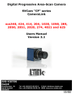
User’s Manual DAGE-MTI Excel Series CCD Digital Cameras & Exponent Software Table of Contents PAGE 3 4 6 6 7 8 8 13 15 15 16 16 17 17 17 18 18 19 19 19 19 19 19 19 19 19 19 19 19 19 20 20 20 20 20 20 20 20 21 21 21 21 21 21 22 22 23 23 Purchaser’s Record Introduction Installation Hardware Requirements IEEE-1394 Card Installation (PC) Exponent Application & Driver Uninstall Exponent Application & Driver Installation Automatic Camera Driver Installation Operation Overview Menu Bar Camera View\Display Mode View\Image Interpolation View\Bayer Algorithm View\Timestamp View\Saturated Pixels View\Toolbox Windows Tools\Options Pause when in Background Tools\Maintenance Help\About Help\User’s Manual Video Window Status Bar Trigger Mode Integration Time Frames per Second Gain Color Gain Camera Controls via Toolbars and Toolbox Camera Toolbar Start Pause Stop Disconnect Camera Memory Presets Toolbar TWAIN Interface Toolbar Image Capture Image Capture w/Filename Dialog Autosave Toolbox Enable Filename Format Source Timelapse Setup Format Toolbar/Toolbox Binning 2 Table of Contents PAGE 23 23 24 24 24 24 25 25 25 25 25 26 26 27 29 29 30 31 31 32 33 34 34 35 36 37 39 41 46 Region of Interest Pixel Depth Exposure Toolbar/Toolbox Exposure Gain Shutter Extended Integration Threshold Color Toolbar/Toolbox Manual One Push Auto Histogram Toolbox Performance Toolbox Trigger Toolbox Strobe Toolbox Miscellaneous Toolbox Auxiliary Connector Back Focus Adjustment Software Development Kit (SDK) Troubleshooting Specifications Excel Camera Spectral Response Excel Camera Quantum Efficiency Excel Camera Mechanical Features Warranty Appendix-A IEEE-1394 Laptop Installation Appendix-B Windows “Found new Hardware Wizard” Driver Install Method Appendix-C Manual Camera Driver Installation Appendix-D Updating Camera Firmware Purchaser’s Record Model Name: □XLVM □XLVC □XL16M □XL16C □XLMM □XLMC Serial Number: Dealer’s Name: Dealer’s Address: Dealer’s Phone Number: Date Purchased: P.O. Number: 3 Introduction Excel Camera Hardware The DAGE-MTI Excel family of digital cameras are based upon the Kodak KAI series of interline transfer, progressive scan, CCD sensors. These high performance sensors have 7.4um square pixels with microlenses to provide high sensitivity and the large full well capacity results in high dynamic range. The XLV camera has 640x480 pixels (VGA) @ up to 75 frames per second. The XL16 camera has 1600x1200 (UXGA) pixels @ up to 16 frames per second and the XLM camera has 2048x2048 pixels @ up to 7.2 frames per second. All models are available with color or monochrome sensors. The Excel cameras operate over an IEEE-1394 Firewire™ bus. For simplistic operation, all that is required for operation is a single IEEE-1394 cable connection between the camera and the PC. An IEEE-1394 PC card and cable are provided with each camera. Optional IEEE-1394 PCMCIA adaptors and cables are available for use with Laptops. The Excel cameras are IIDC version 1.31 compliant set forth by the 1394 Trade Association. Having the cameras adhere to a defined set of guidelines ensures easier integration and consistency for software interface and development. This also allows the cameras to be controlled by 3rd party software designed to control IIDC compliant devices. Full automatic and manual shuttering, gain and extended exposure modes allow for exceptional image results even under difficult lighting conditions. Binning is available in color and monochrome versions to provide increased sensitivity and frame rates for dynamic images. A scalable ROI (Region Of Interest) feature allows viewing and saving of portions of the image area needed. This also allows faster frame rates for dynamic images and smaller saved file sizes. An Auxiliary connector provides an external trigger input and a strobe output for triggered capture to external events. Two General Purpose In/Out (GPIO) pins are also provided for various features such as a Footswitch capture control. The camera mounts to the industry standard C-Mount optics. This allows connection to Microscopes with C-Mount ports as well as C-Mount lenses. A Nikon F-mount adapter is available for adapting the camera lens mount to accept Nikon F lenses. 4 Exponent Camera Software Exponent, a powerful yet easy to use software application, is provided to operate the Excel cameras. This software provides a user friendly approach to set up and operate all the features of the camera. Toolbars provide access to commonly used camera functions while allowing the video display window to have maximum display area. The ToolBox area allows precise control of available camera features and options all laid out in a logical, easy to use menu structure keeping all adjustments handy without having to hunt through menus. The software uses state of the art graphic design for an informative and clean appearance which takes advantage of the “XP” look and feel that everyone is familiar with. Multiple cameras can be used either independently or simultaneously with each having its own software window and set of controls. This allows the user full control to view the video, make adjustments and decide which camera is active without having those annoying floating adjustment menus or confusion as to which menu operates each camera. Three image viewing options are available. The image can be displayed mapping the sensor pixels 1:1 with the monitors’ displayed pixels or fit the whole sensors’ field of view to the display window or fit the sensors’ field of view to the monitors’ “Full Screen” view. Camera memory presets allow the user to recall up to 15 sets of camera adjustments plus a factory default. These presets remain in the camera memory so the camera can switch locations and the stored presets can still be used. A status bar indicates current pertinent information such as the displayed frame rate, integration time, gain and trigger status. Either the Image Capture button, TimeLapse acquisition, external Trigger or a General Purpose Input can be set to operate the Auto Save feature. This allows images to be automatically named, numbered and placed into a user specified folder. In addition to capturing special events a footswitch can be used to view and capture live images while keeping both hands free to operate a microscope or other piece of equipment. This can save valuable time over having to click a capture, key in a name, and then finally save an image. Camera Firmware and Drivers can all be loaded from the Tools menu. This insures the user can update newly released camera features without downtime due to sending equipment back to the factory. A TWAIN driver is included which allows Exponent to import images into your favorite applications. The DAGE-MTI Excel family of cameras and Exponent software provide a high performance, easy to use and versatile solution to Digital Imaging. • • • • • • • System Contents: Excel series Camera IEEE-1394 PC Card IEEE-1394 Cable Exponent Software Twain Driver BackFocus Wrench User’s Manual Options: IEEE-1394 PCMCIA Card & P/S kit P/N: 207744-03 (Laptops w/o 1394 port) 4-6 Pin IEEE-1394 Cable & P/S Kit P/N:207744-04 (Laptops w/1394 port) Auxiliary I/O Cables IEEE-1394 Cables Footswitch Control, P/N: 207765-01 • • • • • 5 Installation Hardware Requirements The Excel cameras and the Exponent application program are designed to run on a PC with Windows XP® (SP1 & SP2). Direct-X 9.0C will be installed during software installation if needed. Also Microsoft .NET version 1.1 may need to be installed for XP SP1 users only. An update link is provided during software installation. Included is an IEEE-1394 Firewire™ card for installation into a PCI bus slot of your computer. This card is recommended for use since it has been verified to perform with the cameras. Other optional IEEE-1394 PCMCIA (CardBus) cards and cables are available for use on Notebooks or Laptop PCs. See “IEEE-1394 Laptop Installation” in Appendix-A. Minimum PC requirements are: • Intel Pentium 4, 1.7GHz or compatible processor • 128MB of RAM • Integrated or dedicated display card set to 1024x768 (or higher); 24 or 32-bit color Optimum PC Requirements are: • Intel Pentium 4, 2.8GHz (or faster) or compatible processor • 512MB RAM (or more) • Dedicated video display card (AGP or PCI-Express Bus) Performance is dependent on whether other applications are running and video display card performance and settings. Although the cameras will operate at other settings, it is recommended that the display card properties be set to 1024x768 pixels @ 24 or 32-bit color for Excel XLV camera and 1600x1200 pixels @ 24 or 32-bit color for Excel XL16 and XLM cameras. You can usually check these settings by “right clicking” on your desktop, select “properties” then the “settings” tab. To install the Exponent software and associated camera drivers and IEEE-1394 hardware you will need to complete the following steps in this order: 1. Install the PCI card into an available PCI slot. 2. Remove any old Exponent software. 3. Install the new Exponent software. 4. Connect the camera to your computer. 5. Install Excel camera drivers. 6. Test the installation. NOTE: You must install the Exponent software and device driver before connecting the camera to your computer; otherwise your computer will not use the correct driver. If this happens, you may need to manually install the driver. 6 IEEE-1394 Card Installation (PC) An IEEE-1394 PCI bus card is included with each camera. Installing the 1394 PCI OHCI (Open Host Controller Interface) card is very similar to installing other PCI devices. Upon successful installation of the card, Windows Device Manager will have an “IEEE 1394 Bus host controller” listed. Please follow the documentation supplied with your PC for information on how to open the case and install a PCI device. The following is a general guideline to installing the hardware card into a PC. 1. 2. 3. 4. Turn off your PC. Unplug your PC. Open the PC case. Use a ground strap to connect you to the chassis of the PC. This will reduce the possibility of any damage due to static electricity. 5. Install the included IEEE-1394 card into an empty PCI bus slot in your computer. 6. Remove ground strap and reassemble computer. 7. Power up computer, the Windows operating system should recognize and install the proper drivers automatically. You may need your Windows OS CDROM if it is asked for during setup. You can verify the card is installed by accessing the “Windows Device Manager”. (“Rightclick” the “My Computer” icon, select “Properties”, navigate to the “Hardware” tab and click “Device Manager”.) IEEE-1394 Card listing in Device Manager 7 Exponent Application & Driver Uninstall If you have previously installed Exponent software and want to install a newer version, you will need to complete the following steps: 1. Uninstall all (attached) cameras from the system by locating the camera in the “Windows Device Manager”, “right-click” the device, and select “Uninstall”. (To access the “Windows Device Manager”- “Right-click” the “My Computer” icon, select “Properties”, navigate to the “Hardware” tab and click “Device Manager”) 2. Unplug the camera. 3. Go to the “Start” Menu and open the “Control Panel”. Use “Add/Remove Programs” to remove Exponent software from your computer. Alternatively there is an uninstall option available if you run the setup disk used to originally install the software. IMPORTANT: To insure correct operation of new software and drivers, the old software and drivers must be removed prior to installing the new versions. Do not use the “uninstall” option contained in newer versions to remove older software versions. (Use the original setup disk or “Add/Remove Programs” inside Windows “Control Panel” to uninstall) Exponent Application & Driver Installation Insert the DAGE-MTI EXPONENT Installation CD into the computer’s CDROM drive. If the Auto Run Wizard does not automatically start after placing the installation CD in the drive, browse to your CD-ROM directory and run the “Exponent Installer.msi” file. The Exponent Setup Wizard will be launched. Read the Warning and click “Next”. NOTE: You must install the Exponent software and device driver before connecting the camera to your computer; otherwise your computer will not use the correct driver. If this happens, you may need to manually install the driver. 8 Exponent is ready to be installed; click “Next”. The destination to install Exponent software will default to “C:\Program Files\Dage Technologies\Exponent\”; accept this designation or click “Browse” to setup a different designation. Decide if you want “Everyone” or “Just me” as users for Exponent software, then click “Next” to proceed. 9 Click “Next” to Confirm the Installation The file copy process will begin: 10 The License Agreement for installing Microsoft DirectX 9.0c will open; read, accept the agreement and click “Next” to proceed. The DirectX Setup window will open; click “Next” to proceed. 11 The DirectX Installation is Complete; Click “Finish” Exponent is fully installed; click “Close”. Exponent requires the Microsoft .NET version 1.1 (or later) framework which is included in Windows XP (SP2). XP (SP1) users may need to install the .NET framework. The installer will direct you to the Microsoft update link to retrieve the .NET components. if needed. The installation automatically places a “Shortcut to Dage Exponent” icon on the desktop and a “Dage Exponent” launch icon is also added to your “Programs” list in the “Start” menu for starting the application. 12 Automatic Camera Driver Installation There are two methods of automatic driver installation: a built in driver install within the Exponent software application, and the Windows Hardware Wizard. The Exponent software driver install method below is the preferred method and should provide a foolproof install. The Windows “Found New Hardware” wizard driver installation is also an acceptable method which is covered in Appendix-B. NOTE: The camera driver process must be performed for each camera used. Exponent Software Camera Driver Install Method After Exponent software has been installed, start the Exponent software application before connecting the Excel camera to the computer. Connect the 1394 cable to the 1394 PCI card and the camera. The “Found New Hardware Wizard” may start. Select “Cancel” in order to use the Exponent Driver Install. At this time the Exponent software application should recognize a new Excel camera. Click “Yes” to begin driver installation. 13 If for some reason the new camera was not recognized, you may manually start the driver install by selecting “Install Drivers” within the “Tools/Maintenance” menu. A Windows Logo Testing Warning will appear, click “Continue Anyway”. The “Installing Driver” window will appear and finish the installation, and then the camera will begin operation. Installation Notes The camera driver installation must be performed for each camera installed on your computer. Multiple cameras can be connected to your computer simultaneously. 14 Operation Overview After installation, the Exponent application software creates a shortcut icon on the desktop. There also is a “Dage Exponent” launch icon added to your “Programs” list in the “Start” menu. The default Dage Exponent application executable is located in “C:\Program Files\Dage Technologies\Exponent”. The Dage Exponent software provides access to all of the camera’s various features. When multiple cameras are used on the same Firewire interface, each camera has its own software window and set of controls. The Title Bar at the top of the application indicates the name of the software and allows the standard windows minimize, maximize, and close options. In addition, a user defined “Camera Name” is displayed when provided by the user in the Miscellaneous Toolbox. If the user has not supplied a name, the software defaults to the Dage Model and Serial Number. The Exponent application provides the following functions: • Live display and capture of image data. • Camera control for: o Shutter Speed and extended exposure control o Gain Control o Exposure Level o Extended Integration Threshold control o 8-bits or 16-bits per pixel selection o Region Of Interest (ROI); size and location o Binning mode for color and monochrome cameras o Black Level Offset o White Balance; manual, One Push, and Auto o Sensor Bayer pattern processing algorithm selection o Trigger input support o Strobe output support o General Purpose Input/Output support o User Defined Camera Name (stored in camera) • File format support of TIFF, BMP, JPG, PNG and GIF. • Full screen image view, Fit to Window and 1:1 mapped viewing choices • Image Interpolation selections for viewing resized image data • TWAIN Interface for import into applications • Auto Save to disk feature • TimeLapse Image Acquisition • 15 Camera User Presets (& factory default) for storing and recalling settings • Camera selection bus support allowing multiple cameras • Histogram graph for viewing exposure • Performance graph for viewing frame rates and computer performance • Informative Status Bar • Saturated Pixel Viewer • Software control of downloading and installing Camera Firmware updates • Built in Camera Driver Installation from software 15 Dage Exponent Software Main Window CAMERA NAME MENU BAR TOOLBOX TOOLBARS VIDEO WINDOW STATUS BAR Menu Bar- Allows access to the various software & camera functions via drop down menus. • Camera- Shows and gives access to the cameras on the Firewire network. Selecting another camera will start another instance of Exponent software with the selected camera. Each camera will have its own window and set of adjustments. Note: The IEEE-1394 bus bandwidth may be exceeded when running multiple cameras. This may cause image “tearing” or “breakup”; to alleviate this problem set all cameras to “Pause When in Background” in the “Tools\Options” menu or manually pause cameras. Also increasing the Shutter time may use less bus bandwidth. 16 • • View\Display Mode- Controls the video window display mode choice of “1:1”, “Fit to Window”, “Full Screen”, and “None”. This menu can also be accessed through a right mouse click in the display window. o 1:1- The video is displayed with a 1:1 pixel-to-pixel relationship between the camera and the display. Scroll bars are placed (if needed) on the Right and the Bottom of the display allowing navigation within the video window. o Fit to Window- The cameras’ full field of view is displayed so that it takes up the entire available video window. In this mode, the video may look distorted as the video is stretched or compressed to fit the available space. The image interpolation algorithm selected in the “Tools\Options\Image Interpolation” dialog is used to remap the camera’s image to the computer screen. o Full Screen- When placed in this display mode, the cameras’ full field of view takes up the entire monitor display. In this mode, the video may look distorted as the video is stretched or compressed to fit the available space. The image interpolation algorithm selected in the “Tools\Options\Image Interpolation” dialog is used to remap the camera’s image to the computer screen. To return to the software, strike any key or click the mouse. o None- No video display is rendered. Images can still be saved. View\Image Interpolation- Allows the choice of various interpolation algorithms for the displayed image when using “Fit to Window” or “Full Screen” display modes. It should be noted that these algorithms can slow the video update display rate of the image. Algorithm acceptability depends on the amount of resizing used and the needed update speed. The Interpolation selection is used for displayed images and has no bearing on actual saved images. o Nearest Neighbor- This algorithm uses the closest neighboring pixel to determine a missing pixel value. The fastest and least computational. o Bilinear- This algorithm uses the weighted average of the nearest 2x2 pixels to determine a missing pixel value. Very fast, more computational. o High Quality Bilinear- Same as Bilinear except a modified weighted average gives a higher quality. o Bicubic- This algorithm uses the weighted average of the nearest 4x4 pixels to determine a missing pixel value. Slower and highly computational. o High Quality Bicubic- Same as Bicubic except a modified weighted average gives a higher quality. 17 • View\Bayer Algorithm- Allows the choice of various Bayer color array demosaicking algorithms for processing of the color sensor image data. Algorithm acceptability depends on the scene contents, quality and the needed update speed. The algorithm selection is applied at the PC on the “raw” image data from the sensor, therefore it should be noted that these algorithms can slow the video update display rate. Unlike the “View\Image Interpolation” setting described above, this algorithm selection is applied to displayed and saved images. o Bilinear Interpolation- This non-adaptive algorithm uses the weighted average of the nearest pixels within a 3x3 block to determine a missing pixel value. Good results in smooth regions of images. Note we do not offer a “Nearest Neighbor” algorithm which just copies the nearest pixel value. The “Bilinear” algorithm gives considerably better results. This default algorithm is the fastest and least computational. o Edge Sensing- This adaptive algorithm outperforms the “Bilinear” approach in textured regions and edges of images by using an adaptive edge direction interpolation where the area around each pixel is analyzed to determine if a preferred interpolation direction exists. The interpolation direction is chosen to interpolate along any edges in the image and to avoid interpolation across edges. Still a fast algorithm, although more computational than the Bilinear algorithm. o Color Correction- This adaptive algorithm analyzes for edges as in the “Edge Sensing” algorithm and also performs processing to preserve color hue. This algorithm provides the best image quality with the tradeoff of higher computational load on the PC. Significantly “zoomed in” area showing algorithm differences Bilinear Interpolation Edge Sensing Color Correction • View\Timestamp- Controls whether the timestamp is displayed/embedded in image. • View\Saturated Pixels- Useful for use in monochrome or color cameras to determine which areas of the image may have saturated data by colorizing only the pixels at maximum level. The Exposure control can then be used to correct for any areas which may be overexposed. o Highlight- Enables the saturated pixel highlighter. Note the colorized highlight data is only for display purposes and is not saved in the actual image file. o Color- Determines the highlighted color from a color palette. 18 • View\Toolbox Windows- Allows control of individual Toolbox visibility. Can also expand all and collapse all as well as turn off the ToolBox display. There is also a “ToolBox” icon in the ToolBar which toggles the ToolBox display. • Tools\Options o • Pause When in Background- Stops video updates when another window overlays. This is useful in multi-camera applications in order to conserve bandwidth or to unburden the PC when simultaneously using other applications. Tools\Maintenance- Allows access to various camera maintenance functions. o Check Web for Updates- Launches the web browser and takes you to the Dage Website to check for the latest Software and Firmware Updates. o Update Camera Firmware- Camera Firmware Updates downloaded from the Dage Website can be downloaded to the camera via this control. The update asks for the location of the binary firmware file, then automatically downloads it to the camera via the Firewire interface and reboots the camera when done. See Appendix-D Updating Camera Firmware for additional information. o Reboot Camera: Allows the camera to be rebooted remotely without having to remove the camera power. o Install Drivers: Allows Dage Camera Drivers to be installed. This will not normally be needed as the drivers are installed when the Software is installed. o Camera Debug Console: An engineering interface that allows direct access of various parts of the camera’s control. This is not a user control and is therefore not accessible without support from Dage Technical Support. • Help\About- Provides the Software Version, Firmware Version, and Camera Serial Number. • Help\User’s Manual- Opens a compiled HTML Help file similar to this manual. Video Window- Receives the video from the camera and displays it on the monitor. The window display mode choice can be accessed either through the “View\Display Mode” menu or by right clicking on the video display window. The video window display mode choice of “1:1”, “Fit to Window”, “Full Screen”, and “none” can be selected as described in the previous section: “Menu Bar\View\Display Mode”. Status Bar- This bar at the bottom of the software provides status updates on various camera functions. • Trigger Mode- Shows the camera’s trigger mode and status. When in a triggered mode or auto trigger greater than 1 second, the indicator will show when the camera is waiting for an input. • Integration Time- Shows the current integration time in seconds. • Frames Per Second- Shows the received frame rate from the camera. • Gain- Shows the current overall gain setting of the camera in dB. • Color Gain- Shows the individual color gain settings (when a color camera is used). 19 Camera Controls- There are many camera controls and each of them is accessible via the software, either through a Toolbar, a Toolbox, or both. Toolbars- Provides quick access to the most common functions for convenience and to allow users to close the Toolbox for a maximum video display area. Toolbox- Each camera function has its own toolbox that allows additional control. These toolboxes can be minimized or turned off by the Toolbox button to allow additional room within the software window to display video. • Camera Toolbar- Allows the camera to either Start, Pause, Stop, or Disconnect. o Start- Connects the camera and begins live video display and camera control. o Pause- Freezes the current image until camera is un-paused. o Stop- Stops the video image, but maintains connection to the camera. o Disconnect- Totally disconnects the connection to the camera. • Camera Memory Presets Toolbar- The camera is capable of storing (Store) and recalling (Load) individual camera presets for all of the cameras’ settings. Memory Preset 0 is reserved for a factory default preset and cannot be overwritten, however Presets 1 through 15 are available. Just setup the camera and set the Preset number to the desired preset, then click the Store button. To load specific stored settings, just set the Preset number to the desired preset and click Load. When an unused preset is recalled, the camera merely ignores the recall and retains the current settings. • TWAIN Interface Toolbar- Exponent has a TWAIN interface that allows transfer of a camera image to another software application. When another program selects the Excel TWAIN interface and acquires a picture, the Exponent software opens and allows camera control via the Exponent software and video transfer to the requesting application. During software installation, a TWAIN data source was added to the “Windows/TWAIN32” directory. Any TWAIN compliant software application you may be using can use the driver to capture images directly into the application. TWAIN compliant applications usually provide an “Import” feature for capturing images from cameras or scanners. Simply select the “Dage Excel Twain Data Source” device in the TWAIN source menu of “Available Devices” in your application. o TWAIN Transfer- Transfers the video image in Exponent to the requesting application. o TWAIN Close- Closes the TWAIN Interface between Exponent and the requesting application. 20 • Image Capture- Works with the AutoSave Toolbox to provide a single button image capture and also is used to start the Timelapse Image Acquisition. The image Filename & Filetype (for 8-bit or 16-bit Format) is set within the AutoSave dialog, and then the Image Capture button saves the image or starts the Timelapse sequence. • Image Capture w/Filename Dialog- Single image file save with standard Windows dialog to save image location, name and type. • AutoSave Toolbox- The camera’s image can be automatically saved in a variety of ways and the AutoSave Toolbox allows the user to control the details in an image save. o Enable- Turns the AutoSave functionality on and off. o Filename- Determines the filename and directory location for image saves. Once the filename is determined, successive image saves are consecutively numbered using the chosen filename and a number (Image 1, Image 2, etc.). This allows for easy collection of multiple images without having to name each image. o Format- 8-bit or 16-bit format is determined by the Format Toolbar/Toolbox. This dialog allows the user to choose the Filetype for whichever format selection is being used. This choice is limited to only those filetypes supported by that particular format. For instance, JPG and GIF do not support 16-bit formats. 21 o o Source- Chooses the input control for an image capture. Image Capture Button- The image capture is controlled by the Image Capture Toolbar button. Successive button pushes places successive camera images into the directory. Timelapse Image Acquisition- When the Image Capture Toolbar button is pressed, Exponent saves successive images in the directory as controlled by the TimeLapse Setup in the lower portion of the Autosave Toolbox. The Image Capture Toolbar button is lit during the timelapse sequence, then extinguishes when the timelapse sequence has completed. Trigger Input- The Trigger Input Source allows image saves per the setup in the Trigger Toolbox. Camera images are saved each time the camera is triggered, whether software or external. See the “Trigger Toolbox” and “Auxiliary Connector” sections for more information. General Purpose Input- This choice uses the GPIO-1 input pin located on the camera’s Auxiliary Connector which can be used with a “Footswitch” to allow hands free image capture. If the input is grounded, the camera image is frozen and stored per the Autosave Toolbox. When the input is released, the image goes back to live view. See the “Auxiliary Connector” section for more information on the optional footswitch and using the GPIO-1 input. Timelapse Setup- Provides control for the number of images and the time between image captures when the “Timelapse Image Acquisition” is chosen as the Autosave source. 22 • Format Toolbar/Toolbox- Allows control of three video format functions: Binning, ROI, and Pixel Depth. o Binning- Binning is the process of summing horizontal and vertical pixels together in order to increase sensitivity and frame rates. For monochrome cameras, three binning modes are supported: None, 2x2, and 4x4. For color cameras, the binning is done by taking either 3 adjacent lines and using two of them for binning (3x3) or 5 adjacent lines and using three of them (5x5). The Binning mode can also be selected via the “Format” Toolbar. Since summed pixels increase sensitivity, the maximum “Gain” control is limited in the highest binning modes to preserve signal to noise performance. o Region of Interest (ROI)- The camera’s imager can be scanned such that only a certain portion of the image is viewed. This function is available in all binning modes. The user draws the ROI desired by choosing the New button and drawing the requested ROI box on the pad in the Format Toolbox. The size of the ROI is listed in pixels (“Horz”-X-“Vert”). The ROI box can then be moved to any position on the camera’s imager by selecting the Move button and dragging the ROI box around in the pad. The full imager can be scanned at any time by choosing the Max button. o Pixel Depth- The camera can support either 8-bit or 16-bit transfer of the 12bit camera image to the PC. Even though the PC display is limited to 8-bits, the image can be saved as a 16-bit file, if desired. When the camera is placed in the 16-bit position, the transfer of the video from the camera to the PC takes twice as long and the video update of the PC will also be half of the 8-bit position. The Bits/Pixel can also be selected via the “Pixel Depth” Toolbar. A 16-bit file will have the upper 12-bits filled with the camera data. Color cameras have the raw (Bayer) image data sent to the PC for color processing into RGB data. 8-bit monochrome and color (24-bit RGB) images can be saved as BMP, TIF, JPG GIF or PNG file formats. 16-bit monochrome images can be saved as TIF or PNG file formats whereas a 16-bit color (48-bit RGB) image can be saved as a PNG file format only. 23 • Exposure Toolbar/Toolbox- Controls the camera’s Exposure by allowing manual or automatic Gain and Shutter settings and the priority of those settings. o Exposure- The Exposure control creates a set point that the Auto Shutter and/or Auto Gain controls use to establish an output video level. Both Shutter and Gain are used to determine the video level; Shutter by controlling the amount of time that light is gathered by the sensor, and Gain applied to the sensor’s signal before digitization. When the Exposure control is in Automatic, the Exposure level is determined by the camera analyzing the video level to determine an ideal set point. The Shutter and/or Gain automatics then set the output level to that point. In the Manual Exposure mode, the video set point is determined by the user adjusting the Exposure control. Exposure can be adjusted or put into automatic mode from the Exposure Toolbox or the Exposure Toolbar. The Exposure gauge (& number) shown in the Toolbar (empty/0 to full/100) is a representation of the minimum to maximum range. The Histogram Toolbox and the highlighter to view Saturated Pixels can be very useful tools for setting correct exposure. o Gain- The Gain control can be used to provide gain (amplification) to the sensor’s output signal. In Auto Gain mode, the camera automatically determines the Gain to achieve a correctly exposed image in accordance with the Exposure control. The Auto Gain control is deactivated at Shutter times in excess of 500 milliseconds. Gain can be adjusted or put into automatic mode from the Exposure Toolbox or the Gain Toolbar. The Gain gauge (& number) shown in the Toolbar (empty/0 to full/100) is a representation of the minimum to maximum range. The actual gain in dB is displayed in the Status Bar. o Shutter- The Shutter control determines the length of time in which the CCD sensor is exposed. Shutter times of 1ms-to-500 milliseconds are controlled via the Shutter Toolbar, while in the Exposure Toolbox; the Shutter time can be extended to 60 seconds. In Auto Shutter mode, the camera automatically determines the shutter time to achieve a correctly exposed image in accordance with the Exposure control. Auto Shutter is limited to 500 milliseconds. Longer Shutter times require the camera to operate in the manual Shutter mode. The Shutter can be adjusted or put into automatic mode from the Exposure Toolbox or the Shutter Toolbar. The Shutter gauge (& number) shown in the Toolbar (empty/0 to full/100) is a representation of the 1ms-500ms range. The actual shutter time is displayed in the Status Bar. 24 o • Extended Integration Threshold (EIT)- Extended integration is when the integration (shutter time) is longer than what is required to run the maximum frame rate. The maximum frame rate varies depending on the camera model, whether Binning and/or ROI are being used and whether using 8-bit or 16-bit operation. This control is active when the camera is in both Auto Gain and Auto Shutter and also is used when switching Binning modes to calculate the new exposure when the camera exposure time is able to run into the extended period. Best Image Quality end- The exposure control will extend integration time out all the way to 500 milliseconds (if needed) before adding gain to achieve the auto exposure level. This operation maintains the lowest possible noise video signal however, may reduce the frame rate if the required exposure ends up into the extended integration time. Highest Frame Rate end- The exposure control will add all available gain (if needed) before increasing the shutter time into the extended integration period, thereby preserving the frame rate. Values in between- Allows a portion from 0% (Best Image Quality) to 100% (Highest Frame Rate) of maximum available gain to be used (if needed) before increasing the Shutter time into the extended integration period. Color Toolbar/Toolbox- (Color Cameras) These controls adjust individual color gain controls for setting white balance. The Gain gauge (& number) shown in the Toolbar (empty/0 to full/100) is a representation of the min to max range. The actual gain in dB is displayed in the Status Bar. These controls can be set in one of three ways: o Manual- In this mode, the user can adjust the individual color gains either through the Color Toolbox or the Red, Green and Blue gain Toolbars. The Histogram is a useful tool for manual white balancing. It provides individual RGB image values which can be used to assist in the balancing of colors. o One Push- The user can have the camera do the color balance by placing a white scene in front of the camera and clicking the One Push button. It is desirable to have the camera in “Auto Shutter” and/or “Auto Gain” to be sure the image is correctly exposed. The routine can take a few seconds to complete depending on the shutter time used. The RGB gains are saved in the camera until another One Push routine or another mode is selected. o Auto- When Auto is selected, the camera continually white balances. 25 • Histogram Toolbox- The histogram is a graph of the number of pixels (Y) per intensity value (X). The Histogram is a very useful tool for indicating correct scene lighting and black value, and in the case of color, whether the color is balanced. One method of manually white balancing an image is to image a “white reference” subject and then adjust the ”Red”, “Green” and “Blue” gain controls until the histogram curves match. • Proper exposures are usually the result when the data gets close to the 100% intensity at the extreme right side. This would indicate the full dynamic range is used. Performance Toolbox- The performance graph gives data on the performance of the software utilization of the computer. The display shows the video receive rate from the IEEE1394a interface, the computer’s display rate, as well as the amount of time the computer uses to convert the video image for display and the actual time required by the computer to display the image on the screen. This display gives a good indication of how well the computer is handling the video. In the case shown below, the video receive rate is 75 frames per second, but the computer can only display the video at less than 20 frames per second. 26 • Trigger Toolbox- The camera can be setup to coordinate its capture of video frames with an external trigger or an internal software trigger source. The manner in which the camera reacts to the source, the form of the source and its polarity are controlled by the Trigger Toolbox. Refer to the “Auxiliary Connector” section for interconnection of the Trigger and additional information on using the Trigger function. o Mode- The Trigger Mode determines the manner in which the camera is going to begin integration and capture of a video frame. Auto Mode- In this mode, the camera works normally and provides video in accordance with its format settings. Mode 0- A trigger source, either External or Software, starts the integration of the imager and its duration it set via the Shutter control. TRIGGER EXPOSURE DURATION IS “SHUTTER” REGISTER VALUE SENSOR EXPOSURE SENSOR READOUT DATA 27 Mode 1- As in Mode 0, a trigger source starts the integration time, but the duration of the integration is determined by the time between trigger edges as shown below. The Manual control button is used to begin and end the trigger sequence through two separate pushes. TRIGGER EXPOSURE DURATION IS TRIGGER WIDTH SENSOR EXPOSURE SENSOR READOUT DATA o Source- This control is only available in Mode 0 and Mode 1 and determines the source of the trigger: “Software” or “External”. In Software Trigger, the beginning of a video capture is determined by the PC writing to a camera register (or pushing the Manual button). In External mode, the trigger input comes from the External Trigger pin of the camera’s “Aux” connector. o Polarity- Sets the polarity of the external trigger input signal to “Active Low” or “Active High”. o Delay- Sets the delay of the trigger input from the time that the trigger is received until the camera is actually reset. This control is available from 0ms to 1 sec. o Manual- When the “Source” is set to “Software Trigger”, this button can be used to trigger the event as well as write to the appropriate Control Register. See the SDK information for more details. 28 • • Strobe Toolbox- The Strobe provides a synchronous output signal at the start of each frame integration period (reset) to control devices such as an external strobe light, a shutter or other equipment. The Strobe Toolbox is used to configure the external strobe function. Refer to the “Auxiliary Connector” section for interconnection of the Strobe and additional information on using the Strobe function. o Enable- Turns the function “On” and “Off”. o Polarity- Choice of an “Active Low” or an “Active High” output. o Delay- Delays the time from camera reset, to the strobe output, from 0ms to 1sec. o Duration- Sets the actual length of the strobe output signal from 1ms to 1sec. Miscellaneous Toolbox: This Toolbox looks like one of the kitchen drawers: it is the repository of all those items that we need but don’t know where to put. o Black Level- This manual control sets the darkest portion of the output video signal by adding an offset to the signal of about 0% (0) to 6% (100) of full video level. The Black Level control can be helpful to view the very darkest portions of an image. Normal operation however is at “0” with no offset. o General Purpose Input- Tells whether the status of the external GPIO-1 input is “On” (high or open) or “Off” (low or grounded). This de-bounced input can be used with a “footswitch” as described in the “Auxiliary Connector” section or can be accessed by the computer via a status register. o General Purpose Output- Controls the external GPIO-0 output; “On”=High, “Off”=Low. Refer to the “Auxiliary Connector” section for additional information. This output can also be controlled by the computer via a control register. o Camera Name: A convenient name that the user can provide that is displayed in the Title Bar of the software and is stored in the camera. 29 Auxiliary Connector The Excel camera and Exponent application are configured to use a “Trigger” input, a “Strobe” output and two additional GPIO (General Purpose Input/Output) functions. GPIO-0 is configured as an output which is accessed in the “Miscellaneous” Toolbox and can also be used for other functions when controlled by the computer via a control register. GPIO-1 is configured as an input and can be used with an optional “FootSwitch” control or accessed by the computer via a status register. (Refer to the SDK for additional information on using GPIO control and status registers) 6 Pin 1 2 3 4 5 6 1 5 2 4 3 Function Ground Strobe Trigger GPIO-1 (Footswitch) GPIO-0 (Output) +3.3V Aux Connector (Rear View) (Mating connector: Hirose HR10A-10-6P; Dage P/N: 737627-06) • Ground- Connected to the camera’s ground system. • Strobe- The Strobe provides a synchronous output signal at the start of each frame integration period (reset) to control devices such as an external strobe light, a shutter or other equipment. The Strobe can also be used in conjunction with the “Trigger” input allowing synchronization of trigger, strobe and sensor readout to capture special events. The Strobe Toolbox is used to configure the strobe function. The Strobe output is a 3.3V current limited signal compatible with most input devices. • Trigger- The Trigger input allows synchronizing capture to external events and is configured using the Trigger Toolbox. When using an external trigger source, the camera will wait for a trigger input then expose and capture an image immediately when triggered and then return to waiting for the next trigger event. The input can be set to activate on either edge of “TTL” transition. The AutoSave Toolbox can be used to automatically name, number and save each triggered image in a predetermined folder location. Trigger mode-0 and mode-1 can be used as described in the “Trigger Toolbox” section. • GPIO-1 (FootSwitch)- The GPIO-1 input operation has been optimized for use with a “FootSwitch” control to allow hands free image capture while viewing a live image. When the input is grounded, the camera image is frozen and stored per the Autosave Toolbox. When the input is released, the image goes back to live view. For Footswitch operation; setup the AutoSave Toolbox to use the GPIO-1 source and the input will automatically name, number and save each image into the predetermined folder location upon Footswitch activation. The input is software “de-bounced” for operation with an optional footswitch device; DAGE; P/N 207765-01. • GPIO-0 (Output)- GPIO-0 is configured as an output which is accessed in the “Miscellaneous” Toolbox. The GPIO-0 output is a 3.3V current limited signal compatible with most input devices • +3.3V- An auxiliary power source provided for user peripheral devices. This 3.3VDC source can provide up to 100mA and is protected by an internal resetable fuse. 30 Back-Focus Adjustment The Excel cameras are designed with a lens mount insert to allow adjustment of the lens position relative to the camera sensor. This is typically referred to as a “Back-Focus” adjustment. A brass insert is secured by a lock-ring. To adjust the lens position, loosen the lock-ring with the included wrench by rotating the lock-ring counterclockwise. Turn the brass insert clockwise to bring the lens closer to the sensor, and counter clockwise to increase the distance until optimum focus is obtained. Then lock the setting by tightening the lock-ring clockwise. TIGHTEN LOOSEN Software Development Kit (SDK) The Excel cameras use the Unibrain IIDC driver and the Exponent software suite is built upon the Unibrain Fire-i API. Documentation of the Excel camera feature set and the conformance to the IIDC specification along with information on using the Unibrain SDK is included in a “SDK” folder on the Exponent Software Installation Disk. Unibrain drivers are provided for use with our Exponent Software Application as part of the Dage licensing agreement with Unibrain. The Unibrain Fire-i API is available for customers who want to develop their own software application based upon the Unibrain drivers. This provides a continually updated SDK and support base for developers and the Dage Exponent application alike now and in the future. 31 Troubleshooting Camera is not listed under “Camera” in Exponent Application. (Check or try the following): 1. Camera Power On? a. Green LED on camera rear on or flashing? b. IEEE-1394 Cable secure at both ends & using specified cable within length limits? c. If using laptop then need external power supply and special cables. (See “Laptop Installation”) 2. Camera Hardware Driver Installed? a. Try “Manual Camera Driver Installation” (Page-18) 3. IEEE-1394 Card Driver Installed? a. Verify card listing in “Device Manager” (Page-7) 4. Proper version of Microsoft DirectX Installed during Exponent software install? a. Go to “Start\Run” on PC and type “dxdiag”. Check for version 9.0C (or later) and run diagnostics if necessary. Image “tears” or “rips” in Video Display. (Check or try the following): 1. Using supplied IEEE-1394 Host adapter? a. The supplied adapter meets OHCI (Ver 1.0/1.1) and IEEE Std 1394a-2000 @ 400M bits/s. Thoroughly tested to work with camera and software. b. Other adapters may work if meet above spec & use TI or VIA chipsets. 2. Using Multiple Cameras; therefore exceeding the IEEE-1394 bus Bandwidth Limit? a. Set some/all cameras to “Pause when in Background” under “Tools\Options” menu. b. Set “Shutter” speed to reduce the Frame Rate (frames per second) on cameras in order to reduce bandwidth requirements. Image is Dark or Saturated. (Check or try the following): 1. Light Level Too Low or too High? a. Open/Close Camera Lens. b. Set “Gain” &/or “Shutter” &/or “Exposure” Control(s) into “Auto”. Image has Dark Corners or Circular Area of Image (Porthole Effect): 1. Lens Format Correct? a. Use a larger format lens. See Specifications for imager size when selecting lens. Colorimetry or White Balance is Incorrect: 1. Use a white object to image before using “One Push” white balance. 2. Set “Shutter” and “Gain” to “Auto” before balance. 3. Light Color Temperature beyond Limits of Camera. a. Try adjusting light source or use color correction filters. b. Try “Manual White Balance” while using “Histogram”. Get Error when Opening Saved Images in Other Programs: 1. Other Application Doesn’t Support 16-bit monochrome or 48-bit color RBG Files? a. Set Bit Depth “Bits per Pixel” to “8-bits” before saving images. 2. Other Application Doesn’t Support “File Type”? a. Try another file type such as BMP or TIF. NOTE: Excel Cameras have a built in “Power On Self Test” feature. The camera will communicate any errors via the LED on the camera rear. Normal operation is a steady green when power is first applied and then flashes with each transmitted video frame. If the LED is flashing red, then the self test has failed. Contact the Dage Customer Service department for further information if the Power on Self Test has failed. 32 Specifications Sensor: (Kodak Prog-scan Interline) Effective Pixels HxV: Pixel Size: Sensor Size: (Effective diagonal dim) Minimum Lens Format: Frame Rate: Full Scan (8-bit)Mono, 2X-Bin (8-bit)Mono, 4X-Bin (8-bit)Color, 3X-Bin (8-bit)Color, 5X-Bin (8-bit)Power: 12V thru IEEE1394 or Ext Pwr XLV XL16 XLM KAI-0340M KAI-2020M KAI-4021M 640 x 480 1600 x 1200 2048 x 2048 7.4um x 7.4um 7.4um x 7.4um 7.4um x 7.4um 5.02mm 14.8mm 21.4mm 1/3” 1”, 2MegaPixel >1”, 4MegaPixel 75 fps 16 fps 7.2 fps 112 fps 28 fps 13.2 fps 150 fps 40 fps 21.3 fps 120 fps 35 fps 17.5 fps 165 fps 45 fps 24 fps <3.5Watts <4.5Watts <6Watts Common Specifications for All Models: Signal/Noise: 58dB or better Bit Depth A/D: 12-bit A/D Converter (requires 16-bit file) Bit Depth File: 8-bit or 16-bit (mono); 24-bit RGB or 48-bit RGB (Color) Image File Formats: BMP, TIF, JPG, GIF, & PNG (8-bit mono & 24-bit RGB) TIF & PNG (16-bit mono); PNG (48-bit RGB) Gain: Automatic & Manual; 0-25dB (mono), 0-21.5dB (color) Shutter: Automatic- 1ms to 500ms; Manual- 1msec to 60sec Binning: None, 2x2, 4x4 (mono); None, 3x3, 5x5 (color) ROI: User Selectable and Continuously Variable, 64x64 Minimum White Balance: Manual- 0 to +10db range; Red, Green & Blue Single Push- Auto Balance to Scene & Lock Setting Auto- Continuously Auto Balance on Scene (Auto Tracking) Black Level: 0 to 6% of Full Video Level Video Viewing: 1:1, Fit to Window & Full Screen Video Interpolation: Bilinear, Bicubic, Nearest Neighbor, High Quality Bilinear & Bicubic Timestamp: Embedded in Image; On or Off Memory Presets: Factory Default plus 15 User Defined. Stored in Camera Friendly Name: 32 Characters Stored in Camera and Displayed on Title Bar of Software Histogram: Live View of Image Data & with Individual Colors when using Color Camera Interface: Single Cable 6Pin IEEE-1394 (Firewire) for Camera Control, Power & Video Data Camera Specification: IIDC 1394 Digital Camera Spec V1.31 of 1394 Trade Association External Trigger Modes: Auto: Camera Continuously Integrates and Captures based upon Exposure Settings Mode0: Camera Reset via Software or Ext Trigger. Integration Time set via Software. Mode1: Camera Reset via Software or Ext Trigger. Integration Time set via Trigger Width External Strobe: 3.3V Frame Reset Output with Programmable Delay, Duration, & Polarity External GPIO: One Input, One Output. Access via Software, 0 to +3.3V, Current Limited External Control Power: +3.3VDC, Output limited to 100mA, Resetable Fuse Protected Alternate External Power: +12VDC Input w/auto Disconnect of IEEE1394 Power Drivers: Unibrain Drivers and SDK TWAIN Driver: Driver Installed with Exponent Application Camera Firmware: Updateable via Exponent Software Lens Mount: C-Mount with Adjustable Back Focus, Nikon F-Mount Adapter Optional Weight: 25 oz (711g) Operating Temperature: 0ºC to +40 ºC Standards Compliance: CE, FCC, part 15 class B, EN55103-1 Class B, EN55103-2 33 Excel Camera Spectral Response Note: Monochrome cameras have an “Anti-Reflective” coated clear window fitted in the Cmount focus ring to protect the sensor. This is not an IR cut filter. Color cameras have an “IR Cut” color balancing filter fitted in the C-mount focus ring. Monochrome Color: Blue, Green, Red IR Cut Response Excel Camera Quantum Efficiency • Monochrome Cameras: 55% @ 460nm • Color Cameras: Blue: 41% @ 460nm Green: 37% @ 540nm Red: 31% @ 620nm 34 Excel Camera Mechanical Features Back Focus Lock Tripod Mount 1½”W x 1 ¼”D (¼”-20 tapped hole, 0.4” Deep) 2.5” Deep 4” Dia 0.45” High 1.65” ¼-20 Tripod to C-Mount IEEE-1394 Firewire™ Port Auxiliary Connector External Power Power Indicator 35 Warranty DAGE-MTI EXCEL Cameras are warranted to be free of defects in material and workmanship in normal use for a period of two years from the original date of purchase from DAGE-MTI. This warranty does not apply to units which have been subject to abuse, neglect, accident, improper installation, or on which the serial number has been removed or damaged. Units that have been altered without the prior permission of DAGE-MTI are not covered by this warranty. This warranty does not apply to other equipment furnished by DAGE-MTI, which is listed or otherwise identified as manufactured by another and therefore shall be covered by the other manufactures’ applicable warranty. This warranty is valid only if the malfunctioning unit is returned to DAGE-MTI service depot; this warranty does not cover on-location service. If warranty work is needed, the following should be contacted: DAGE-MTI of MC, INC. Customer Service 701 N. Roeske Ave. Michigan City, IN 46360 (219) 872-5514 [email protected] This warranty does not cover: • Problems caused by or inflicted upon associated equipment such as computers, digitizing systems, video tape recorders, cameras, microscopes, etc. • Damage caused by accident, misuse, improper power source, fire, flood, lightning, other acts of God, war, and repair or alteration by other than a DAGE-MTI authorized service organization. • Labor or incurred charges required in removing or installing the product, down time, failure of the product to perform properly, and any consequential damages. • Transit damage. Unit must be properly packaged (in original packing, if possible) when being returned under warranty. 36 Appendix-A IEEE-1394 Laptop Installation Excel cameras are powered by the IEEE-1394 bus. Laptop computers usually have no provision to power connected devices, therefore the Excel cameras have an external power input connector to operate the camera on Laptops. First determine if your laptop computer already has an IEEE-1394 port. Typically Laptops come equipped with a port using a 4-pin miniature IEEE-1394 connector. A. If your computer already is equipped with an IEEE1394 port, then you will need to use a 4pin to 6-pin IEEE-1394 cable along with a “12 Volt Power Supply” to power the camera and connect the IEEE-1394 bus. The Cable & Power Supply are available as a kit. (Dage P/N 207744-04) 1. Install the Exponent software Application. (Directions start on Page-8) 2. Use the 4-pin to 6-pin IEEE-1394 cable to connect the Camera to the Computer. 3. Start the Exponent Software application and then connect the Power Supply to the “EXT PWR” connector on the camera. 4. Install the camera driver following the “Exponent Software Camera Driver Install” method. (Directions start on Page-13) 5. Begin using your camera. POWER SUPPLY LAPTOP EXCEL CAMERA IEEE-1394 Cable 4-PIN 37 6-PIN B. If your Laptop computer does not have an IEEE-1394 port, then you will need to install an “IEEE-1394 PCMCIA CardBus” card and use a standard 6-pin to 6-pin cable along with a “12 Volt Power Supply” to power the camera and connect the IEEE-1394 bus. The IEEE1394 Card, Cable and Power Supply are available as a kit. (Dage P/N 207744-03) 1. Install the PCMCIA CardBus card into your Laptop. 2. Windows XP will automatically install the driver for the card. Reboot computer if prompted. 3. Install the Exponent software Application. (Directions start on Page-8) 4. Connect the Camera to the CardBus card using a 6-pin to 6-pin IEEE-1394 cable. 5. Start the Exponent Software application and then connect the Power Supply to the “EXT PWR” connector on the camera. 6. Install the camera driver following the “Exponent Software Camera Driver Install” method. (Directions start on Page-13) 7. Begin using your camera. POWER SUPPLY LAPTOP IEEE-1394 Cable 6-PIN CardBus Card 38 EXCEL CAMERA Appendix-B Windows “Found New Hardware Wizard” Driver Install Method NOTE: The “Exponent Software Camera Driver Install” method is the preferred method and should provide a foolproof install; however the Windows “Found New Hardware Wizard” below can also be used if desired. After Exponent software has been installed, connect the 1394 cable to the 1394 PCI card and the camera. The “Found New Hardware Wizard” will start. Select “No, not this time” to connect to Windows Update, then select “Next”. NOTE: This step is not used with Windows XP Service Pack 1 version. Be sure the Windows Hardware Wizard finds a “Unibrain Fire-I driver / DageMTI XL” camera. Select “Install the software automatically” then click “Next”. 39 A Windows Logo Testing Warning will appear, click “Continue Anyway”. The “Completing the Found New Hardware Wizard” window will appear, click “Finish” This completes the process for installing the camera driver. Start Exponent software and the camera will begin operation. 40 Appendix-C Manual Camera Driver Installation NOTE: This operation is only required when the automatic driver installation fails or the incorrect camera driver is installed and you need to force the hardware driver to accept the proper driver. From within the Windows Device Manager (“Control Panel/System/Hardware/Device Manager”) the camera should be listed as “Unibrain Fire-I driver / DageMTI XL” (under “Imaging Devices”). If for some reason the device is listed incorrectly as "Generic 1394 Desktop Camera" or has a yellow asterisk or some other incorrect listing, then ”right click” on this device and select "Update Driver". 41 The "Hardware Update Wizard" will start. Select "Install from a list or specific location". Click "Next". Select "Don't search. I will choose the driver to install". Click "Next. 42 Under “Show Compatible Hardware” select “Unibrain Fire-I driver / DageMTI XL” and then click “next”. If “Unibrain Fire-I driver / DageMTI XL” is not in the list then click the "Have Disk" option and browse to find the driver located in the default directory “C:\Program Files\Dage Technologies\Exponent\Driver” and choose the “fidcam.inf” driver file. NOTE: Clicking “Have Disk” will add the next 3 steps Click “OK” to the location to the “fidcam.inf” driver file. 43 Now pick “Unibrain Fire-I driver / DageMTI XL” as the compatible hardware. 44 A Windows Logo Testing Warning will appear, click “Continue Anyway”. The “Completing the Found New Hardware Update Wizard” window will appear, click “Finish” From within the Windows Device Manager (“Control Panel/System/Hardware/Device Manager”) the camera should now be listed as “Unibrain Fire-I driver / DageMTI XL” (under “Imaging Devices”). 45 Appendix-D Updating Camera Firmware NOTE: This operation is only required when camera operation can benefit from the updated firmware. Updated firmware may be needed in order to use new features in Exponent Software updates or if camera operation has been updated or optimized. Refer to the information on the Dage Website for details concerning the need or benefits of updating firmware compared to the firmware version in your camera. Camera “Firmware” is the “embedded software” contained in the camera. It is responsible for controlling the hardware operation and interface to the Exponent software application. Updates can be downloaded from the Dage Website, and then downloaded to the camera through the Exponent application using the IEEE-1394 Firewire interface. There is no need for a special application, opening of the camera or returning the camera to provide firmware updates. If you believe your camera can benefit from a firmware update, use the following procedure. 1. Check the version of firmware in your camera by going to the “Help” menu and selecting “About”. 2. To check for firmware updates and receive information concerning new firmware versions, go the Dage website. Access to the site is available by selecting “Check Web for Updates” in the “Tools\Maintenance” menu or by visiting “www.dagemti.com”. 3. If new firmware is indicated, download the new firmware binary file from the Dage Website and save the file to a convenient location on your computer. 4. Go to the “Update Firmware” utility in the “Tools\Maintenance” menu. The update asks for the location of the binary firmware file you saved earlier in step 3, and then automatically downloads it to the camera. Click “OK” when finished and the camera will reboot. Be sure not to unplug the camera during the update process. Verify the firmware version has been updated by going to the “Help” menu and selecting “About” as in step 1. 46 DAGE-MTI DAGE-MTI of MC, Inc. 701 N. Roeske Ave. Michigan City, IN 46360 (219) 872-5514 www.dagemti.com 970005-01C Exponent Version 1.300 2/21/06 47