1
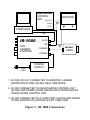
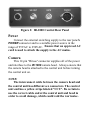
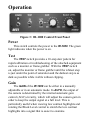
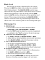
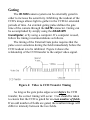
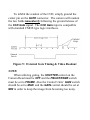
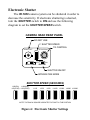
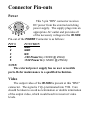
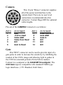
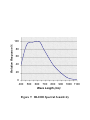
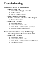
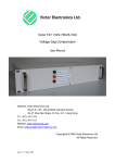
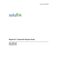
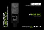
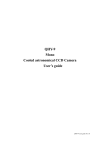
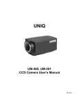
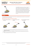
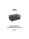
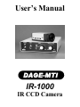
User’s Manual
DAGE-MTI
IR-1000
IR CCD Camera
Purchaser’s Record
Model Name: DAGE-MTI IR-1000
Serial Number:
Dealer’s Name:
Dealer’s Address:
Dealer’s Phone Number:
Date Purchased:
P.O. Number:
Introduction
The DAGE-MTI IR-1000 camera system is based upon a
1/2" Interline CCD that produces high-resolution imaging
into the near IR spectrum. The CCD employs a state of the art
microlens design to increase the light gathering capability of
the CCD. The simplistic front panel design of the IR-1000
control unit allows easy access to the Gain and Black Level
controls that provide a vast adjustment range. A Test switch
provides a stair step pattern for rapid calibration or
troubleshooting of the attached equipment such as a monitor
or frame grabber. The read-out of the sensor can be inhibited
by an external Gate pulse, which allows increased integration
times in low-light level situations.
The flexibility of the DAGE-MTI IR-1000 camera system
makes it the camera of choice in almost any imaging
situation.
DAGE-MTI offers our customers state-of-the-art video
technology… with an eye on your image.
Installation
The IR-1000 camera head connects directly into the
control unit. Power for the control is supplied by an external
switching supply that is provided. Ensure that a correct AC
power cord is used in accordance with local safety standards.
All power and interconnections to the IR-1000 camera head
are supplied through the single interface cable. Gating can be
accomplished by simply using the DAGE-MTI Investigater to
control the gate time, display and store the image, or by using
a computer with a frame grabber. Figure 1 shows some
typical setups of the IR-1000.
INVESTIGATER
CONTROL
UNIT VID OUT
VID IN
MONITOR
2
GATE
COMPUTER
3
IR-1000
CCD
CAMERA
CONTROL
POWER
CORD
GATE
VID
1
CAMERA
IR-1000
HEAD
POWER
POWER
SUPPLY
1. IR-1000 VID OUT CONNECTED TO MONITOR. CAMERA
OPERATION IN ‘NON GATING’ REAL TIME MODE.
2. IR-1000 CONNECTED TO INVESTIGATER CONTROL UNIT.
GATING AND FRAME STORE OPERATION CONTROLLED BY
INVESTIGATER CONTROL UNIT.
3. IR-1000 CONNECTED TO A COMPUTER. GATING AND FRAME
STORE OPERATION CONTROLLED BY COMPUTER.
Figure 1: IR-1000 Connections
Figure 2: IR-1000 Control Rear Panel
Power
Connect the external switching supply to the rear panel's
POWER connector and to a suitable power source in the
range of 95VAC to 250VAC. Ensure that an approved AC
cord is used to attach the supply to the AC mains.
Camera
This 12-pin ‘Hirose’ connector supplies all of the power
and interface to the IR-1000 camera head. Always ensure that
the camera head is attached to the control unit before turning
the control unit on.
NOTE:
The interconnect cable between the camera head and
the control unit has different sex connectors. The control
unit end has a yellow stripe labeled “CCU”. Be certain to
use the correct cable end at the control unit and head in
order to avoid damage, which could void the warrantee.
Video
This ‘BNC’ connector supplies video output of the
IR-1000 system. The signal is 1Vp-p terminated into 75Ω.
Be careful to avoid double termination of the output video,
which would result in incorrect video levels. Connect to a
monitor, computer or the DAGE-MTI Investigater as
required.
NOTE:
Do not use the VIDEO OUT connector on the camera
head. This will cause incorrect video levels to be sent to
the control and the signal at the camera head will be
double terminated.
Gate
This ‘BNC’ connector can be used to provide input of a
gate pulse in order to increase the sensitivity by inhibiting the
readout of the CCD's image and allowing light to gather in
the CCD for extended periods of time before readout.
Connect to a computer or the DAGE-MTI Investigater.
Operation
Figure 3: IR-1000 Control Front Panel
Power
This switch controls the power to the IR-1000. The green
light indicates when the power is on.
Test
The TEST switch provides a 10-step stair pattern for
rapid calibration or troubleshooting of the attached equipment
such as a monitor or frame grabber. With the TEST switch
on, adjust the monitor or frame grabber until the whitest step
is just under the point of saturation and the darkest step is as
dark as possible while visible without clipping.
Gain
The GAIN of the IR-1000 can be either in a manually
adjustable or in an automatic mode. In AUTO, the output of
the camera is determined by the internal automatic gain
control (AGC) circuitry, which will adjust the camera gain in
order to keep the output signal at a full level. This is
particularly useful when viewing low contrast highlights and
rotating the Black Level control to stretch the low contrast
highlights into a signal that is easier to examine.
Black Level
The black level output is determined by this control.
When set to MAX, the output video resides on a standard
50mV black pedestal. The BLACK LEVEL control range
allows blacks to be pulled down so that whites can be contrast
enhanced and stretched. Using this mode with the GAIN
control in AUTO stretches the portion of the signal that is of
interest. When using external gating, the BLACK LEVEL
control is useful for removing unwanted light offsets due to
effects such as lens scattering and low level background light.
Microscope Use
A. Initial Set-up:
1. Set switches on rear of camera head as follows:
SHUTTER to OFF, FIELD/FRAME to FRAME.
2. Use the TEST signal to adjust the associated equipment
as outlined in the “Test” section on the previous page.
B. All Forms of Transmitted Light:
1. Set GAIN to AUTO and BLACK LEVEL to MAX.
2. Adjust light so white highlights are just under saturation.
3. Turn BLACK LEVEL control for the proper contrast.
C. Live or Real-time Fluorescence:
1. Set for best visual fluorescence using eyepieces.
2. Set GAIN to AUTO and BLACK LEVEL to MAX.
3. Turn BLACK LEVEL control for best black background.
D. Gated low Light Level Fluorescence:
1. Follow steps 1-3 in part C above for live fluorescence.
2. Set GAIN to MAN and control to MIN.
3. Select Gate (Integration) time and initiate.
Note: Increasing MAN GAIN can shorten the Gate time.
However, this may cause the image to be very noisy.
Gating
The IR-1000 camera system can be externally gated in
order to increase the sensitivity. Inhibiting the readout of the
CCD's image allows light to gather in the CCD for extended
periods of time. An external gating pulse defines the gate
time of the camera through the GATE connector. Gating can
be accomplished by simply using the DAGE-MTI
Investigater, or by using a computer. If a computer is used,
follow the timing recommendations as follows.
The timing of the External Gate pulse requires that the
pulse occur sometime during the field immediately before the
CCD readout is to be inhibited. Figure 4 shows the
relationship of the CCD transfer to the output video signal.
Figure 4: Video to CCD Transfer Timing
As long as the gate pulse edges occur before the CCD
transfer, the correct timing will occur. Care should be taken
to ensure that the CCD is gated for an even number of fields.
If an odd number of fields are gated, the resultant image will
differ in intensity between the two fields.
To inhibit the readout of the CCD, simply ground the
center pin on the GATE connector. The camera will readout
the two fields immediately following the ground release of
the CCD Gate signal. The CCD Gate input is compatible
with standard CMOS type logic interfaces.
Figure 5: External Gate Timing & Video Readout
NOTE:
When utilizing gating, the SHUTTER control on the
Camera Head must be OFF and the FIELD/FRAME switch
must be set to FRAME. Also the Control Units’ GAIN switch
should be set to MAN, and the GAIN control should be set at
MIN in order to keep the image from becoming too noisy.
Electronic Shutter
The IR-1000 camera system can be shuttered in order to
decrease the sensitivity. If electronic shuttering is desired,
turn the SHUTTER switch to ON and use the following
diagram to set the SHUTTER SPEED switch.
CAMERA HEAD REAR PANEL
DO NOT USE
SHUTTER SPEED
VIDEO OUT
DC IN/SYNC
TO CONTROL
OFF
ON
FIELD FRAME
SHUTTER
SHUTTER ON/OFF
INTEGRATION MODE
SHUTTER SPEED (SECONDS)
1/60(EIA) 1/100(EIA)
1/50(CCIR) 1/120(CCIR)
1/125
1/250
1/500
1/1000
1/2000
1/4000 1/10000
NOTE: THE BLACK SQUARE INDICATES THE SWITCH TAB POSITION
Figure 6: Electronic Shutter Settings
Connector Pin-outs
Power
This 5-pin ‘DIN’ connector receives
DC power from the external switching
power supply. The supply plugs into an
appropriate AC outlet and provides all
35 241
of the necessary voltages to the IR-1000.
Pin-out of the POWER Connector is as follows:
PIN #
1
2
3
4
5
FUNCTION
GND
GND
N/C
-12V Power In (-12VDC @ 25mA)
+12V Power In (+12VDC @ 275mA)
NOTE:
The external power supply has no user accessible
parts. Refer maintenance to a qualified technician.
Video
The output video of the IR-1000 is present at this ‘BNC’
connector. The signal is 1Vp-p terminated into 75Ω. Care
should be taken to avoid no termination or double termination
of the output video, which would result in incorrect video
levels.
Camera
1
2
9
8
10
3 11 12 7
4
6
5
This 12-pin ‘Hirose’ connector supplies
all of the power and interface to the
camera head. There are no user level
connections recommended into this
connector. Contact Dage-MTI for optional
cable lengths.
Pin-out of the CAMERA Connector is as follows:
PIN #
1
2
3
4
5
6
FUNCTION
GND
+12V to Head
Video GND
Video from Head
N/C
Gain to Head
PIN #
7
8
9
10
11
12
FUNCTION
Head Auto Gain
Gate GND
Gate In
N/C
N/C
N/C
Gate
This ‘BNC’ connector can be used to provide input of a
gate pulse in order to increase the sensitivity by inhibiting the
readout of the CCD's image and allowing light to gather in
the CCD for extended periods of time before readout.
Connect to a computer or the DAGE-MTI Investigater. The
CCD Gate input is compatible with standard CMOS type
logic interfaces. (+5V=Readout; Gnd=Gate)
Specifications:
Pick-up Device:
Signal to Noise:
Shading:
Sensitivity:
Minimum Illumination:
1/2" Interline CCD w/microlens
56db
<5% overall
.05 fc (0.5 lux) @ 3200K
.00035 fc (.0035 lux)
Horizontal Resolution:
Effective Vertical Lines:
Pixel Clock Freq:
Vertical Rate:
Horizontal Rate:
RS-170
768(H) x 494(V)
8.4um(H) x
9.8um(V)
570 TVL
485 (2:1 interlace)
14.318 MHz.
59.94 Hz.
15,734 Hz.
Weight:
Control Unit
Power Supply
Camera Head
1.48 lb. (0.67 Kg.)
0.75 lb. (0.34 Kg.)
0.25 lb. (.11 Kg.)
Size:
Control Unit
Power Supply
Camera Head
5½"(W) x 1½"(H) x 8"(L)
2½"(W) x 1¾"(H) x 4"(L)
1¾"(W) x 11/8"(H) x 3¾"(L)
Operating Temperature:
0°C to +40°C
Input Voltage:
95VAC to 250VAC
Active Picture Elements:
Picture Element Size:
CCIR
752(H) x 582(V)
8.6um(H) x
8.3um(V)
560 TVL
575 (2:1 interlace)
14.1875 MHz.
50 Hz.
15,625 Hz.
Relative Response %
100
80
60
40
20
0
400
500
600
700
800
900 1000 1100
Wave Length (nm)
Figure 7: IR-1000 Spectral Sensitivity
Troubleshooting
No Picture (Check or try the following):
1. Camera Power On?
a. External Power Supply Attached?
b. AC Power On?
c. LED on Control Unit On?
2. Head Connected to Control?
3. Monitor Connected to Control Video Output?
a. Monitor Power On?
3. Light Level Too Low?
a. Open Camera Lens.
b. Set Gain Control into Auto.
c. Rotate Black Level Control to Maximum.
d. Set Head Shutter Control to Off.
Picture Saturated: (Check or try the following):
1. Video Output Cable Terminated Into 75Ω?
2. Light Level Too High?
a. Reduce Lens Setting.
b. Set Gain Control into Auto.
c. Rotate Black Level Control towards Minimum.
d. Use Shutter Control.
Warranty
The DAGE-MTI IR-1000 is warranted to be free of
defects in material and workmanship in normal use for a
period of one year from the original date of purchase from
DAGE-MTI.
This warranty does not apply to units which have been
subject to abuse, neglect, accident, improper installation, or
on which the serial number has been removed or damaged.
Units that have been altered without the prior permission of
DAGE-MTI are not covered by this warranty.
This warranty does not apply to other equipment
furnished by DAGE-MTI, which is listed or otherwise
identified as manufactured by another and therefore shall be
covered by the other manufactures’ applicable warranty.
Limitations
1. This warranty is valid only if the malfunctioning unit is
returned to DAGE-MTI service depot. This warranty does
not cover on-location service. If warranty work is needed,
the following should be contacted:
DAGE-MTI, INC.
Customer Service
701 N. Roeske Ave.
Michigan City, IN 46360
(219) 872-5514
Fax: (219) 872-5559
[email protected]
2. This warranty does not cover:
a. Problems caused by or inflicted upon associated
equipment such as digitizing systems, video tape
recorders, cameras, microscopes, etc.
b. Damage caused by accident, misuse, improper power
source, fire, flood, lightning, other acts of God, war,
and repair or alteration by other than a DAGE-MTI
authorized service organization.
c. Labor or incurred charges required in removing or
installing the Product, down time, failure of the
Product to perform properly, and any consequential
damages.
d. Transit damage.
3. Unit must be properly packaged (in original packing, if
possible) when being returned under warranty.
DAGE-MTI Inc.
701 N. Roeske Ave.
Michigan City, IN 46360
(219) 872-5514
Fax: (219) 872-5559
E-mail: [email protected]
http://www.dagemti.com
970150-01
8/1/02